charge INFINITI QX4 2001 Factory Service Manual
[x] Cancel search | Manufacturer: INFINITI, Model Year: 2001, Model line: QX4, Model: INFINITI QX4 2001Pages: 2395, PDF Size: 43.2 MB
Page 36 of 2395
SAT015J
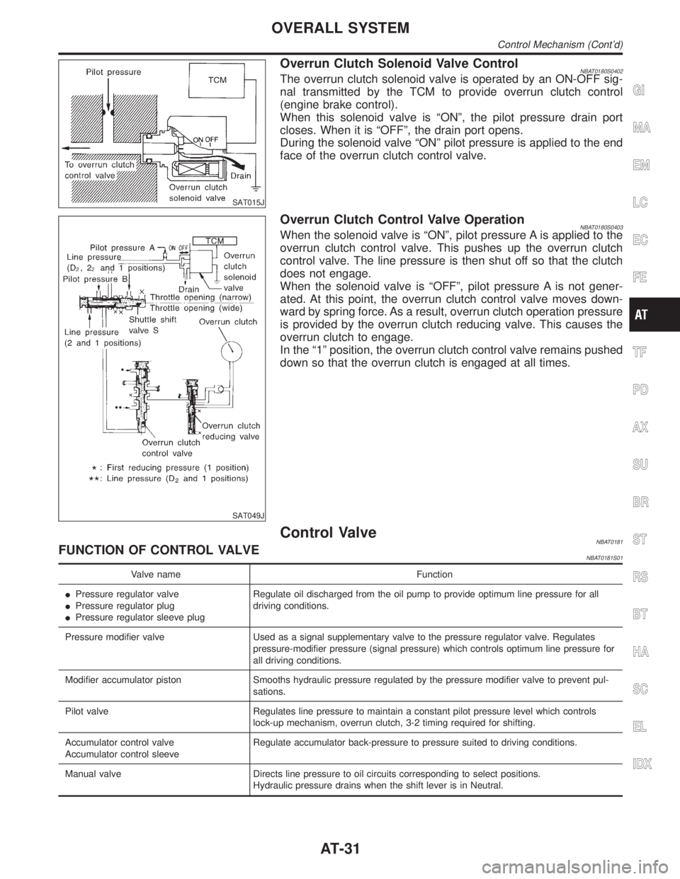
Overrun Clutch Solenoid Valve ControlNBAT0180S0402The overrun clutch solenoid valve is operated by an ON-OFF sig-
nal transmitted by the TCM to provide overrun clutch control
(engine brake control).
When this solenoid valve is ªONº, the pilot pressure drain port
closes. When it is ªOFFº, the drain port opens.
During the solenoid valve ªONº pilot pressure is applied to the end
face of the overrun clutch control valve.
SAT049J
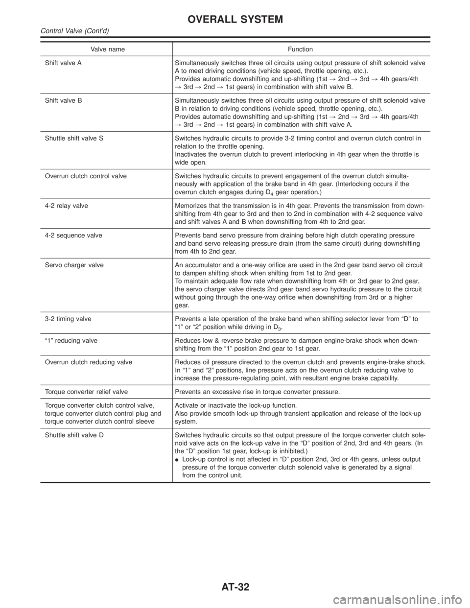
Overrun Clutch Control Valve OperationNBAT0180S0403When the solenoid valve is ªONº, pilot pressure A is applied to the
overrun clutch control valve. This pushes up the overrun clutch
control valve. The line pressure is then shut off so that the clutch
does not engage.
When the solenoid valve is ªOFFº, pilot pressure A is not gener-
ated. At this point, the overrun clutch control valve moves down-
ward by spring force. As a result, overrun clutch operation pressure
is provided by the overrun clutch reducing valve. This causes the
overrun clutch to engage.
In the ª1º position, the overrun clutch control valve remains pushed
down so that the overrun clutch is engaged at all times.
Control ValveNBAT0181FUNCTION OF CONTROL VALVENBAT0181S01
Valve name Function
IPressure regulator valve
IPressure regulator plug
IPressure regulator sleeve plugRegulate oil discharged from the oil pump to provide optimum line pressure for all
driving conditions.
Pressure modifier valve Used as a signal supplementary valve to the pressure regulator valve. Regulates
pressure-modifier pressure (signal pressure) which controls optimum line pressure for
all driving conditions.
Modifier accumulator piston Smooths hydraulic pressure regulated by the pressure modifier valve to prevent pul-
sations.
Pilot valve Regulates line pressure to maintain a constant pilot pressure level which controls
lock-up mechanism, overrun clutch, 3-2 timing required for shifting.
Accumulator control valve
Accumulator control sleeveRegulate accumulator back-pressure to pressure suited to driving conditions.
Manual valve Directs line pressure to oil circuits corresponding to select positions.
Hydraulic pressure drains when the shift lever is in Neutral.
GI
MA
EM
LC
EC
FE
TF
PD
AX
SU
BR
ST
RS
BT
HA
SC
EL
IDX
OVERALL SYSTEM
Control Mechanism (Cont'd)
AT-31
Page 37 of 2395
Valve name Function
Shift valve A Simultaneously switches three oil circuits using output pressure of shift solenoid valve
A to meet driving conditions (vehicle speed, throttle opening, etc.).
Provides automatic downshifting and up-shifting (1st,2nd,3rd,4th gears/4th
,3rd,2nd,1st gears) in combination with shift valve B.
Shift valve B Simultaneously switches three oil circuits using output pressure of shift solenoid valve
B in relation to driving conditions (vehicle speed, throttle opening, etc.).
Provides automatic downshifting and up-shifting (1st,2nd,3rd,4th gears/4th
,3rd,2nd,1st gears) in combination with shift valve A.
Shuttle shift valve S Switches hydraulic circuits to provide 3-2 timing control and overrun clutch control in
relation to the throttle opening.
Inactivates the overrun clutch to prevent interlocking in 4th gear when the throttle is
wide open.
Overrun clutch control valve Switches hydraulic circuits to prevent engagement of the overrun clutch simulta-
neously with application of the brake band in 4th gear. (Interlocking occurs if the
overrun clutch engages during D
4gear operation.)
4-2 relay valve Memorizes that the transmission is in 4th gear. Prevents the transmission from down-
shifting from 4th gear to 3rd and then to 2nd in combination with 4-2 sequence valve
and shift valves A and B when downshifting from 4th to 2nd gear.
4-2 sequence valve Prevents band servo pressure from draining before high clutch operating pressure
and band servo releasing pressure drain (from the same circuit) during downshifting
from 4th to 2nd gear.
Servo charger valve An accumulator and a one-way orifice are used in the 2nd gear band servo oil circuit
to dampen shifting shock when shifting from 1st to 2nd gear.
To maintain adequate flow rate when downshifting from 4th or 3rd gear to 2nd gear,
the servo charger valve directs 2nd gear band servo hydraulic pressure to the circuit
without going through the one-way orifice when downshifting from 3rd or a higher
gear.
3-2 timing valve Prevents a late operation of the brake band when shifting selector lever from ªDº to
ª1º or ª2º position while driving in D
3.
ª1º reducing valve Reduces low & reverse brake pressure to dampen engine-brake shock when down-
shifting from the ª1º position 2nd gear to 1st gear.
Overrun clutch reducing valve Reduces oil pressure directed to the overrun clutch and prevents engine-brake shock.
In ª1º and ª2º positions, line pressure acts on the overrun clutch reducing valve to
increase the pressure-regulating point, with resultant engine brake capability.
Torque converter relief valve Prevents an excessive rise in torque converter pressure.
Torque converter clutch control valve,
torque converter clutch control plug and
torque converter clutch control sleeveActivate or inactivate the lock-up function.
Also provide smooth lock-up through transient application and release of the lock-up
system.
Shuttle shift valve D Switches hydraulic circuits so that output pressure of the torque converter clutch sole-
noid valve acts on the lock-up valve in the ªDº position of 2nd, 3rd and 4th gears. (In
the ªDº position 1st gear, lock-up is inhibited.)
ILock-up control is not affected in ªDº position 2nd, 3rd or 4th gears, unless output
pressure of the torque converter clutch solenoid valve is generated by a signal
from the control unit.
OVERALL SYSTEM
Control Valve (Cont'd)
AT-32
Page 167 of 2395

SAT341H
DescriptionNBAT0057The line pressure solenoid valve regulates the oil pump discharge
pressure to suit the driving condition in response to a signal sent
from the TCM.
The line pressure duty cycle value is not consistent when the
closed throttle position switch is ªONº. To confirm the line
pressure duty cycle at low pressure, the accelerator (throttle)
should be open until the closed throttle position switch is
ªOFFº.
CONSULT-II REFERENCE VALUE IN DATA MONITOR
MODE
NBAT0057S02Remarks: Specification data are reference values.
Monitor item Condition Specification
Line pressure solenoid
valve dutySmall throttle opening (Low line pressure)
"
Large throttle opening (High line pressure)Approximately 24%
"
Approximately 95%
NOTE:
The line pressure duty cycle value is not consistent when the closed throttle position switch is ªONº. To confirm the line pressure duty
cycle at low pressure, the accelerator (throttle) should be open until the closed throttle position switch is ªOFFº.
TCM TERMINALS AND REFERENCE VALUENBAT0057S03Remarks: Specification data are reference values.
Terminal
No.Wire color Item ConditionJudgement
standard
(Approx.)
1GYLine pressure
solenoid valve
When releasing accelerator pedal after warm-
ing up engine.1.5 - 3.0V
When depressing accelerator pedal fully after
warming up engine.0V
2 BR/YLine pressure
solenoid valve
(with dropping
resistor)When releasing accelerator pedal after warm-
ing up engine.5 - 14V
When depressing accelerator pedal fully after
warming up engine.0V
ON BOARD DIAGNOSIS LOGICNBAT0057S04
Diagnostic trouble code Malfunction is detected when ... Check item (Possible cause)
: L/PRESS SOL/CIRCTCM detects an improper voltage drop
when it tries to operate the solenoid
valve.IHarness or connectors
(The solenoid circuit is open or shorted.)
ILine pressure solenoid valve
: P0745
DTC P0745 LINE PRESSURE SOLENOID VALVE
Description
AT-162
Page 362 of 2395

Return SpringsNBAT0165Unit: mm (in)
PartsItem
Part No.* Free length Outer diameter
Control valveUpper body1 Torque converter relief valve spring 31742-41X23 38.0 (1.496) 9.0 (0.354)
2 Pressure regulator valve spring 31742-41X24 44.02 (1.7331) 14.0 (0.551)
3 Pressure modifier valve spring 31742-41X19 31.95 (1.2579) 6.8 (0.268)
Ð Accumulator control valve spring Ð Ð Ð
4 Shuttle shift valve D spring 31762-41X01 25.0 (0.984) 7.0 (0.276)
5 4-2 sequence valve spring 31756-41X00 29.1 (1.146) 6.95 (0.2736)
6 Shift valve B spring 31762-41X01 25.0 (0.984) 7.0 (0.276)
7 4-2 relay valve spring 31756-41X00 29.1 (1.146) 6.95 (0.2736)
8 Shift valve A spring 31762-41X01 25.0 (0.984) 7.0 (0.276)
9 Overrun clutch control valve spring 31762-41X03 23.6 (0.929) 7.0 (0.276)
10 Overrun clutch reducing valve spring 31742-41X14 38.9 (1.531) 7.0 (0.276)
11 Shuttle shift valve S spring 31762-41X04 51.0 (2.008) 5.65 (0.2224)
12 Pilot valve spring 31742-41X13 25.7 (1.012) 9.0 (0.354)
13 Torque converter clutch control valve spring 31742-41X22 18.5 (0.728) 13.0 (0.512)
Lower body1 Modifier accumulator piston spring 31742-27X70 31.4 (1.236) 9.8 (0.386)
2 1st reducing valve spring 31756-60X00 20.5 (0.807) 7.0 (0.276)
3 3-2 timing valve spring 31742-41X06 23.0 (0.906) 6.7 (0.264)
4 Servo charger valve spring 31742-41X06 23.0 (0.906) 6.7 (0.264)
Reverse clutch Ð 31505-41X07 Ð Ð
High clutch10 pcs31521-41X03
(Assembly)24.2 (0.9528) 11.6 (0.457)
Forward clutch (Overrun clutch) 20 pcs31521-41X04
(Assembly)35.77 (1.4083) 9.7 (0.382)
Low & reverse brake 18 pcs31655-41X00
(Assembly)22.3 (0.878) 11.2 (0.441)
Band servoSpring A 31605-4AX03 45.6 (1.795) 34.3 (1.350)
Spring B 31605-41X01 29.7 (1.169) 27.6 (1.087)
AccumulatorAccumulator A 31605-41X02 43.0 (1.693) 18.0 (0.709)
Accumulator B 31605-41X14 47.6 (1.874) 26.5 (1.043)
Accumulator C 31605-41X09 45.0 (1.772) 29.3 (1.154)
Accumulator D 31605-41X06 58.4 (2.299) 17.3 (0.681)
GI
MA
EM
LC
EC
FE
TF
PD
AX
SU
BR
ST
RS
BT
HA
SC
EL
IDX
SERVICE DATA AND SPECIFICATIONS (SDS)
Return Springs
AT-357
Page 620 of 2395

WORK SUPPORT MODE=NBEC0034S04
WORK ITEM CONDITION USAGE
TP SW/TP SEN IDLE POSI ADJIFOLLOW THE BASIC INSPECTION INSTRUCTION IN
THE SERVICE MANUAL.When adjusting the idle throttle
position
FUEL PRESSURE RELEASEIFUEL PUMP WILL STOP BY TOUCHING ªSTARTº
DURING IDLING.
CRANK A FEW TIMES AFTER ENGINE STALLS.When releasing fuel pressure
from fuel line
IDLE AIR VOL LEARNITHE IDLE AIR VOLUME THAT KEEPS THE ENGINE
WITHIN THE SPECIFIED RANGE IS MEMORIZED IN
ECM.When learning the idle air volume
SELF-LEARNING CONTITHE COEFFICIENT OF SELF-LEARNING CONTROL
MIXTURE RATIO RETURNS TO THE ORIGINAL
COEFFICIENT.When clearing the coefficient of
self-learning control valve
EVAP SYSTEM CLOSE OPEN THE VACUUM CUT VALVE BYPASS VALVE AND
CLOSE THE EVAP CANISTER VENT CONTROL VALVE
IN ORDER TO MAKE EVAP SYSTEM CLOSE UNDER
THE FOLLOWING CONDITIONS.
IIGN SW ªONº
IENGINE NOT RUNNING
IAMBIENT TEMPERATURE IS ABOVE 0ÉC (32ÉF).
INO VACUUM AND NO HIGH PRESSURE IN EVAP
SYSTEM
ITANK FUEL TEMP. IS MORE THAN 0ÉC (32ÉF).
IWITHIN 10 MINUTES AFTER STARTING ªEVAP SYS-
TEM CLOSEº
IWHEN TRYING TO EXECUTE ªEVAP SYSTEM
CLOSEº UNDER THE CONDITION EXCEPT ABOVE,
CONSULT-II WILL DISCONTINUE IT AND DISPLAY
APPROPRIATE INSTRUCTION.
NOTE:
WHEN STARTING ENGINE, CONSULT-II MAY DIS-
PLAY ªBATTERY VOLTAGE IS LOW. CHARGE
BATTERYº, EVEN IN USING CHARGED BATTERY.When detecting EVAP vapor leak
point of EVAP system
TARGET IGNITION TIMING ADJ*IIDLE CONDITIONIWhen adjusting target ignition
timing
After adjustment, confirm target
ignition timing with a timing
light.
IIf once the ªTARGET IDLE
RPM ADJº has been done, the
Idle Air Volume Learning proce-
dure will not be completed.
TARGET IDLE RPM ADJ*IIDLE CONDITION When setting target idle speed
*: This function is not necessary in the usual service procedure.
SELF-DIAGNOSTIC MODENBEC0034S05DTC and 1st Trip DTCNBEC0034S0501Regarding items of ªDTC and 1st trip DTCº, refer to ªTROUBLE
DIAGNOSIS Ð INDEXº (See EC-8.)
Freeze Frame Data and 1st Trip Freeze Frame DataNBEC0034S0502
Freeze frame data
item*1Description
DIAG TROUBLE
CODE
[PXXXX]IThe engine control component part/control system has a trouble code, it is displayed as ªPXXXXº.
(Refer to ªTROUBLE DIAGNOSIS Ð INDEXº, EC-8.)
GI
MA
EM
LC
FE
AT
TF
PD
AX
SU
BR
ST
RS
BT
HA
SC
EL
IDX
ON BOARD DIAGNOSTIC SYSTEM DESCRIPTION
CONSULT-II (Cont'd)
EC-85
Page 653 of 2395

Symptom Matrix ChartNBEC0041SYSTEM Ð BASIC ENGINE CONTROL SYSTEMNBEC0041S01
SYMPTOM
Reference
page
HARD/NO START/RESTART (EXCP. HA)
ENGINE STALL
HESITATION/SURGING/FLAT SPOT
SPARK KNOCK/DETONATION
LACK OF POWER/POOR ACCELERATION
HIGH IDLE/LOW IDLE
ROUGH IDLE/HUNTING
IDLING VIBRATION
SLOW/NO RETURN TO IDLE
OVERHEATS/WATER TEMPERATURE HIGH
EXCESSIVE FUEL CONSUMPTION
EXCESSIVE OIL CONSUMPTION
BATTERY DEAD (UNDER CHARGE)
Warranty symptom code AA AB AC AD AE AF AG AH AJ AK AL AM HA
Fuel Fuel pump circuit11232 2 2 3 2EC-625
Fuel pressure regulator system3344444 4 4 4EC-40
Injector circuit11232 2 2 2EC-616
Evaporative emission system
3344444 4 4 4EC-32
Air Positive crankcase ventilation sys-
tem1 EC-38
Incorrect idle speed adjustment 1 1 1 1 1 EC-101
IACV-AAC valve circuit1123322 2 2 2 2EC-422
Ignition Incorrect ignition timing adjustment33111 1 1 1EC-101
Ignition circuit 1 1 2 2 2 2 2 2 EC-499
Main power supply and ground circuit
22333 3 32
3EC-142
Air conditioner circuit 3 3 2 HA section
1 - 6: The numbers refer to the order of inspection.
(continued on next page)
TROUBLE DIAGNOSIS Ð GENERAL DESCRIPTION
Symptom Matrix Chart
EC-118
Page 654 of 2395
SYMPTOM
Reference
page
HARD/NO START/RESTART (EXCP. HA)
ENGINE STALL
HESITATION/SURGING/FLAT SPOT
SPARK KNOCK/DETONATION
LACK OF POWER/POOR ACCELERATION
HIGH IDLE/LOW IDLE
ROUGH IDLE/HUNTING
IDLING VIBRATION
SLOW/NO RETURN TO IDLE
OVERHEATS/WATER TEMPERATURE HIGH
EXCESSIVE FUEL CONSUMPTION
EXCESSIVE OIL CONSUMPTION
BATTERY DEAD (UNDER CHARGE)
Warranty symptom code AA AB AC AD AE AF AG AH AJ AK AL AM HA
Engine
controlCrankshaft position sensor (REF)
circuit
22EC-510
Crankshaft position sensor (POS)
circuitEC-334, 517
Camshaft position sensor
(PHASE) circuit3EC-342
Mass air flow sensor circuit 1
122
222 2EC-150
Heated oxygen sensor 1 (front)
circuit
3EC-192
Engine coolant temperature sen-
sor circuit1 3 3 EC-169, 187
Throttle position sensor circuit 2 2 EC-174
Incorrect throttle position sensor
adjustment3 1 1 1 1 1 1 1 EC-101
Vehicle speed sensor circuit 2 3 3
3EC-417
Knock sensor circuit 2 EC-328
ECM 2233333 3 33EC-444, 117
Start signal circuit 2 EC-621
Park/Neutral position switch circuit 3 3
333 EC-604
Power steering oil pressure switch
circuit2 EC-634
Electrical load signal circuitEC-644
1 - 6: The numbers refer to the order of inspection.
(continued on next page)
GI
MA
EM
LC
FE
AT
TF
PD
AX
SU
BR
ST
RS
BT
HA
SC
EL
IDX
TROUBLE DIAGNOSIS Ð GENERAL DESCRIPTION
Symptom Matrix Chart (Cont'd)
EC-119
Page 655 of 2395
SYSTEM Ð ENGINE MECHANICAL & OTHERNBEC0041S02
SYMPTOM
Reference
section
HARD/NO START/RESTART (EXCP. HA)
ENGINE STALL
HESITATION/SURGING/FLAT SPOT
SPARK KNOCK/DETONATION
LACK OF POWER/POOR ACCELERATION
HIGH IDLE/LOW IDLE
ROUGH IDLE/HUNTING
IDLING VIBRATION
SLOW/NO RETURN TO IDLE
OVERHEATS/WATER TEMPERATURE HIGH
EXCESSIVE FUEL CONSUMPTION
EXCESSIVE OIL CONSUMPTION
BATTERY DEAD (UNDER CHARGE)
Warranty symptom code AA AB AC AD AE AF AG AH AJ AK AL AM HA
Fuel Fuel tank
5
5FE section
Fuel piping 5 5 5 5 5 5
Ð Vapor lock
Valve deposit
5 555 5 5 5
Poor fuel (Heavy weight gasoline,
Low octane)
Air Air duct
55555 5 Air cleaner
Air leakage from air duct
(Mass air flow sensor Ð throttle
body)
555 5
Throttle body, Throttle wireFE section
Air leakage from intake manifold/
Collector/GasketÐ
Cranking Battery
111111 11
EL section Alternator circuit
Starter circuit 3
Flywheel/Drive plate 6 EM section
PNP switch 4 AT section
1 - 6: The numbers refer to the order of inspection.
(continued on next page)
TROUBLE DIAGNOSIS Ð GENERAL DESCRIPTION
Symptom Matrix Chart (Cont'd)
EC-120
Page 656 of 2395
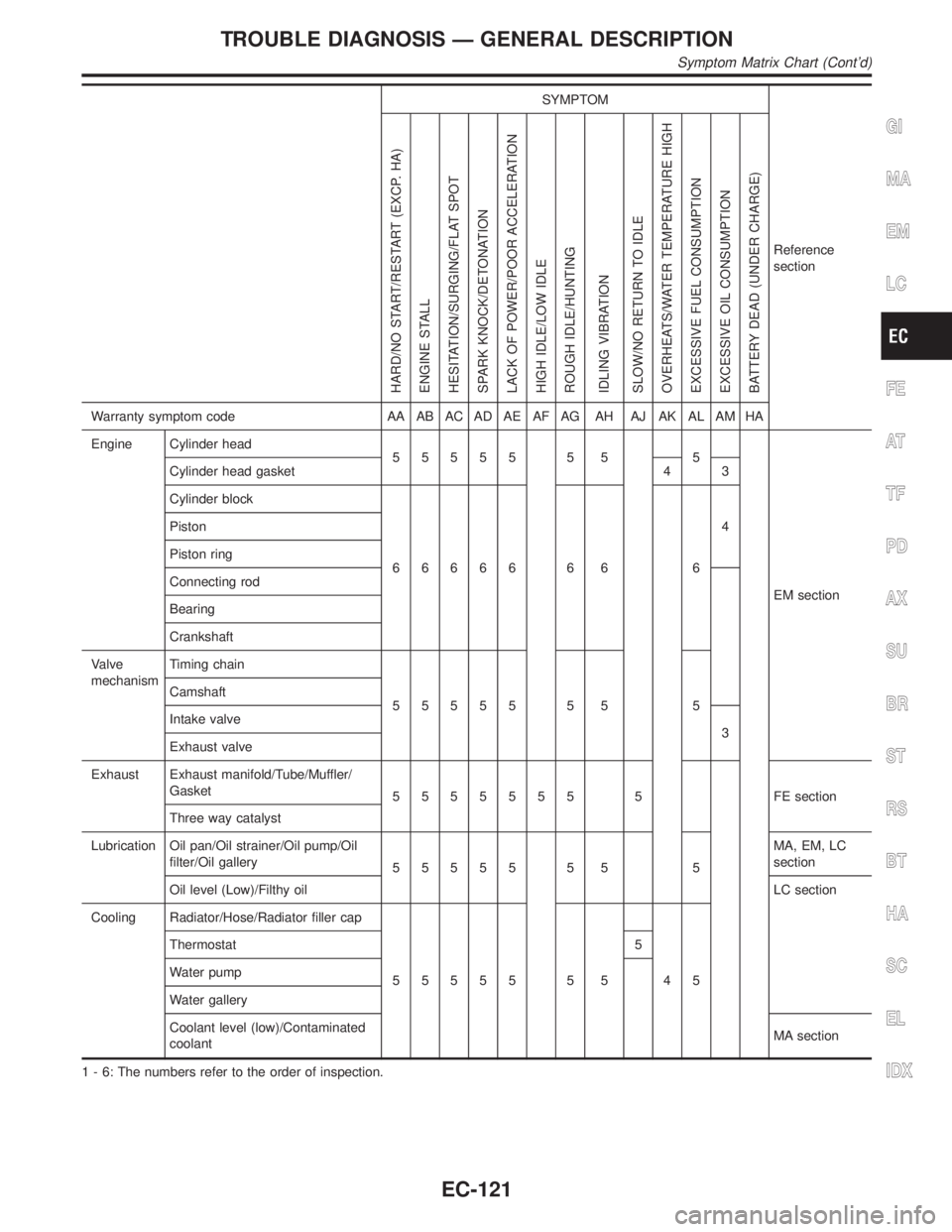
SYMPTOM
Reference
section
HARD/NO START/RESTART (EXCP. HA)
ENGINE STALL
HESITATION/SURGING/FLAT SPOT
SPARK KNOCK/DETONATION
LACK OF POWER/POOR ACCELERATION
HIGH IDLE/LOW IDLE
ROUGH IDLE/HUNTING
IDLING VIBRATION
SLOW/NO RETURN TO IDLE
OVERHEATS/WATER TEMPERATURE HIGH
EXCESSIVE FUEL CONSUMPTION
EXCESSIVE OIL CONSUMPTION
BATTERY DEAD (UNDER CHARGE)
Warranty symptom code AA AB AC AD AE AF AG AH AJ AK AL AM HA
Engine Cylinder head
55555 5 5 5
EM section Cylinder head gasket 4 3
Cylinder block
66666 6 6 64 Piston
Piston ring
Connecting rod
Bearing
Crankshaft
Valve
mechanismTiming chain
55555 5 5 5 Camshaft
Intake valve
3
Exhaust valve
Exhaust Exhaust manifold/Tube/Muffler/
Gasket
5555555 5 FEsection
Three way catalyst
Lubrication Oil pan/Oil strainer/Oil pump/Oil
filter/Oil gallery
55555 5 5 5MA, EM, LC
section
Oil level (Low)/Filthy oilLC section
Cooling Radiator/Hose/Radiator filler cap
55555 5 5 45 Thermostat 5
Water pump
Water gallery
Coolant level (low)/Contaminated
coolantMA section
1 - 6: The numbers refer to the order of inspection.
GI
MA
EM
LC
FE
AT
TF
PD
AX
SU
BR
ST
RS
BT
HA
SC
EL
IDX
TROUBLE DIAGNOSIS Ð GENERAL DESCRIPTION
Symptom Matrix Chart (Cont'd)
EC-121
Page 657 of 2395

SYMPTOM
Reference
section
HARD/NO START/RESTART (EXCP. HA)
ENGINE STALL
HESITATION/SURGING/FLAT SPOT
SPARK KNOCK/DETONATION
LACK OF POWER/POOR ACCELERATION
HIGH IDLE/LOW IDLE
ROUGH IDLE/HUNTING
IDLING VIBRATION
SLOW/NO RETURN TO IDLE
OVERHEATS/WATER TEMPERATURE HIGH
EXCESSIVE FUEL CONSUMPTION
EXCESSIVE OIL CONSUMPTION
BATTERY DEAD (UNDER CHARGE)
Warranty symptom code AA AB AC AD AE AF AG AH AJ AK AL AM HA
IVIS (INFINITI Vehicle Immobilizer System Ð
NATS)11EC-74 or EL
section
1 - 6: The numbers refer to the order of inspection.
CONSULT-II Reference Value in Data Monitor
Mode
NBEC0042Remarks:
ISpecification data are reference values.
ISpecification data are output/input values which are detected or supplied by the ECM at the connector.
* Specification data may not be directly related to their components signals/values/operations.
i.e. Adjust ignition timing with a timing light before monitoring IGN TIMING, because the monitor may show the specification data in
spite of the ignition timing not being adjusted to the specification data. This IGN TIMING monitors the data calculated by the ECM
according to the signals input from the camshaft position sensor and other ignition timing related sensors.
IIf the real-time diagnosis results are NG and the on board diagnostic system results are OK when diagnosing the mass air flow sensor,
first check to see if the fuel pump control circuit is normal.
MONITOR ITEM CONDITION SPECIFICATION
ENG SPEED
CKPS´RPM (POS)ITachometer: Connect
IRun engine and compare tachometer indication with the CONSULT-II
value.Almost the same speed as
the CONSULT-II value.
POS COUNTIEngine: Running 179 - 181
MAS A/F SE-B1IEngine: After warming up
IAir conditioner switch: ªOFFº
IShift lever: ªNº
INo-loadIdle 1.2 - 1.8V
2,500 rpm 1.6 - 2.2V
COOLAN TEMP/SIEngine: After warming up More than 70ÉC (158ÉF)
HO2S1 (B1)
HO2S1 (B2)
IEngine: After warming upMaintaining engine speed at 2,000
rpm0 - 0.3V+,Approx. 0.6 -
1.0V
HO2S1 MNTR (B1)
HO2S1 MNTR (B2)LEAN+,RICH
Changes more than 5 times
during 10 seconds.
HO2S2 (B1)
HO2S2 (B2)
IEngine: After warming upMaintaining engine speed at 2,000
rpm0 - 0.3V+,Approx. 0.6 -
1.0V
HO2S2 MNTR (B1)
HO2S2 MNTR (B2)LEAN+,RICH
TROUBLE DIAGNOSIS Ð GENERAL DESCRIPTION
Symptom Matrix Chart (Cont'd)
EC-122