Battery INFINITI QX4 2001 Factory Service Manual
[x] Cancel search | Manufacturer: INFINITI, Model Year: 2001, Model line: QX4, Model: INFINITI QX4 2001Pages: 2395, PDF Size: 43.2 MB
Page 2121 of 2395

How to Perform Trouble Diagnoses for Quick
and Accurate Repair
=NBRS0041A good understanding of the malfunction conditions can make troubleshooting faster and more accurate.
In general, each customer feels differently about a malfunction. It is important to fully understand the symp-
toms or conditions for a customer complaint.
INFORMATION FROM CUSTOMERNBRS0041S01WHAT ..... Vehicle model
WHEN ..... Date, Frequencies
WHERE ..... Road conditions
HOW ..... Operating conditions, Symptoms
PRELIMINARY CHECKNBRS0041S02Check that the following parts are in good order.
IBattery [Refer to SC-4, ªBATTERYº.]
IFuse [Refer to EL-16, ªFuseº, ªPOWER SUPPLY ROUTINGº.]
ISystem component-to-harness connections
SUPPLEMENTAL RESTRAINT SYSTEM (SRS)
How to Perform Trouble Diagnoses for Quick and Accurate Repair
RS-32
Page 2129 of 2395
![INFINITI QX4 2001 Factory Service Manual SRS701
If no malfunction is detected on ªSELF-DIAG [CURRENT]º even
though malfunction is detected in ªSRS Operation Checkº, check
the battery voltage.
If the battery voltage is less than 9V, charg INFINITI QX4 2001 Factory Service Manual SRS701
If no malfunction is detected on ªSELF-DIAG [CURRENT]º even
though malfunction is detected in ªSRS Operation Checkº, check
the battery voltage.
If the battery voltage is less than 9V, charg](/img/42/57027/w960_57027-2128.png)
SRS701
If no malfunction is detected on ªSELF-DIAG [CURRENT]º even
though malfunction is detected in ªSRS Operation Checkº, check
the battery voltage.
If the battery voltage is less than 9V, charge the battery. Then go
to DIAGNOSTIC PROCEDURE 3, page RS-42.
If the battery voltage is OK, go to DIAGNOSTIC PROCEDURE 4,
page RS-44, to diagnose the following cases:
ISelf-diagnostic result ªSELF-DIAG [PAST]º (previously stored
in the memory) might not be erased after repair.
IThe SRS system malfunctions intermittently.
8. Touch ªPRINTº.
9. Compare diagnostic codes to ªCONSULT-II Diagnostic Code
Chartº, page RS-40.
10. Touch ªBACKº key of CONSULT-II until ªSELECT SYSTEMº
appears in order to return to User mode from Diagnosis mode.
11. Turn ignition switch ªOFFº, then turn off and disconnect
CONSULT-II, and disconnect both battery cables.
12. Repair the system as outlined by the ªRepair orderº in ªCON-
SULT-II Diagnostic Code Chartº, that corresponds to the self-
diagnostic result. For replacement procedure of component
parts, refer to RS-15.
13. After repairing the system, go to DIAGNOSTIC PROCEDURE
3, page RS-42 for final checking.
CONSULT-II Diagnostic Code Chart (ªSELF-DIAG
[CURRENT]º)
NBRS0045S0101
Diagnostic item ExplanationRepair order
ªRecheck SRS at each replace-
ment.º
NO DTC IS
DETECTED.When malfunction is
indicated by the ªAIR
BAGº warning lamp in
User modeILow battery voltage (Less than 9V)IGo to DIAGNOSTIC PROCEDURE 3
(RS-42) after charging battery.
ISelf-diagnostic result ªSELF-DIAG
[PAST]º (previously stored in the
memory) might not be erased after
repair.
IIntermittent malfunction has been
detected in the past.IGo to DIAGNOSTIC PROCEDURE 4
(RS-44).
INo malfunction is detected.IGo to DIAGNOSTIC PROCEDURE 3
(RS-42).
AIRBAG MODULE
[OPEN]IDriver's air bag module circuit is open. (including the spiral
cable)1. Visually check the wiring harness
connection.
2. Replace the harness if it has visible
damage.
3. Replace driver's air bag module.
(Before disposal of it, it must be
deployed.)
4. Replace the spiral cable.
5. Replace the diagnosis sensor unit.
6. Replace the related harness.
SUPPLEMENTAL RESTRAINT SYSTEM (SRS)
Trouble Diagnoses with CONSULT-II (Cont'd)
RS-40
Page 2131 of 2395
![INFINITI QX4 2001 Factory Service Manual Diagnostic item ExplanationRepair order
ªRecheck SRS at each replace-
ment.º
PRE-TEN FRONT LH
[OPEN/VB-SHORT]IThe circuit for front LH pre-tensioner is open or shorted to
some power supply circuit.1 INFINITI QX4 2001 Factory Service Manual Diagnostic item ExplanationRepair order
ªRecheck SRS at each replace-
ment.º
PRE-TEN FRONT LH
[OPEN/VB-SHORT]IThe circuit for front LH pre-tensioner is open or shorted to
some power supply circuit.1](/img/42/57027/w960_57027-2130.png)
Diagnostic item ExplanationRepair order
ªRecheck SRS at each replace-
ment.º
PRE-TEN FRONT LH
[OPEN/VB-SHORT]IThe circuit for front LH pre-tensioner is open or shorted to
some power supply circuit.1. Visually check the wiring harness
connections.
2. Replace the harness if it has visible
damage.
3. Replace front LH seat belt.
(Before disposing, it must be deacti-
vated.)
4. Replace the diagnosis sensor unit.
5. Replace the related harness. PRE-TEN FRONT LH
[GND-SHORT]IThe circuit for front LH pre-tensioner is shorted to ground.
PRE-TEN FRONT RH
[OPEN/VB-SHORT]IThe circuit for front RH pre-tensioner is open or shorted to
some power supply circuit.1. Visually check the wiring harness
connections.
2. Replace the harness if it has visible
damage.
3. Replace front RH seat belt.
(Before disposing, it must be deacti-
vated.)
4. Replace the diagnosis sensor unit.
5. Replace the related harness. PRE-TEN FRONT RH
[GND-SHORT]IThe circuit for front RH pre-tensioner is shorted to ground.
CONTROL UNITIDiagnosis sensor unit is malfunctioning. 1. Visually check the wiring harness
connection.
2. Replace the diagnosis sensor unit.
* Follow the procedures in numerical order when repairing malfunctioning parts. Confirm whether malfunction is eliminated
using the air bag warning lamp or CONSULT-II each time repair is finished. If malfunction is still observed, proceed to the next
step. When malfunction is eliminated, further repair work is not required.
SRS844
DIAGNOSTIC PROCEDURE 3NBRS0045S02Final checking after repairing SRS by using CONSULT-II Ð
Diagnosis mode
1. After repairing SRS, connect both battery cables.
2. Connect CONSULT-II to Data link connector.
3. Turn ignition switch from ªOFFº to ªONº.
SRS695
4. Touch ªSTARTº.
SUPPLEMENTAL RESTRAINT SYSTEM (SRS)
Trouble Diagnoses with CONSULT-II (Cont'd)
RS-42
Page 2135 of 2395

SRS704
9. Diagnostic code is displayed on ªTROUBLE DIAG RECORDº.
10. Touch ªPRINTº.
11. Compare diagnostic codes to ªIntermittent Malfunction Diag-
nostic Code Chartº, page RS-46.
12. Touch ªBACKº key of CONSULT-II until ªSELECT SYSTEMº
appears.
13. Turn ignition switch ªOFFº, then turn off and disconnect
CONSULT-II, and disconnect both battery cables.
14. Repair the system as outlined by the ªRepair orderº in ªInter-
mittent Malfunction Diagnostic Code Chartº, that corresponds
to the self-diagnostic result. For replacement procedure of
component parts, refer to RS-15.
15. Go to DIAGNOSTIC PROCEDURE 3, page RS-42, for final
checking.
Intermittent Malfunction Diagnostic Code Chart (ªSELF-
DIAG [PAST]º or ªTROUBLE DIAG RECORDº)
NBRS0045S0401
Diagnostic item Explanation Repair order
NO DTC IS
DETECTED.When malfunction is
indicated by the ªAIR
BAGº warning lamp in
User modeILow battery voltage (Less than 9V)IGo to DIAGNOSTIC PROCEDURE
3 (RS-42) after charging battery.
INo malfunction is detected.IGo to DIAGNOSTIC PROCEDURE
3 (RS-42).
AIRBAG MODULE
[OPEN]IDriver's air bag module circuit is open. (including the spiral
cable)1. Visually check the wiring harness
connection.
2. Replace the harness if it has visible
damage.
3. If the harness check result is OK,
replace driver's air bag module
(Before disposal of it, it must be
deployed.), diagnosis sensor unit
and spiral cable. AIRBAG MODULE
[VB-SHORT]IDriver's air bag module circuit is shorted to some power sup-
ply circuit. (including the spiral cable)
AIRBAG MODULE
[GND-SHORT]IDriver's air bag module circuit is shorted to ground. (including
the spiral cable)
AIRBAG MODULE
[SHORT]IDriver's air bag module circuits are shorted to each other.
ASSIST A/B MODULE
[VB-SHORT]IFront passenger air bag module circuit is shorted to some
power supply circuit.1. Visually check the wiring harness
connection.
2. Replace the harness if it has visible
damage.
3. If the harness check result is OK,
replace front air bag module
(Before disposal of it, it must be
deployed.), and diagnosis sensor
unit. ASSIST A/B MODULE
[OPEN]IFront passenger air bag module circuit is open.
ASSIST A/B MODULE
[GND-SHORT]IFront passenger air bag module circuit is shorted to ground.
ASSIST A/B MODULE
[SHORT]IFront passenger air bag module circuits are shorted to each
other.
SUPPLEMENTAL RESTRAINT SYSTEM (SRS)
Trouble Diagnoses with CONSULT-II (Cont'd)
RS-46
Page 2137 of 2395

Diagnostic item Explanation Repair order
CONTROL UNITIDiagnosis sensor unit is malfunctioning. 1. Visually check the wiring harness
connection.
2. Replace the harness if it has visible
damage.
3. If the harness check is OK, replace
the diagnosis sensor unit.
* Follow the procedures in numerical order when repairing malfunctioning parts, then make the final system check.
SRS800
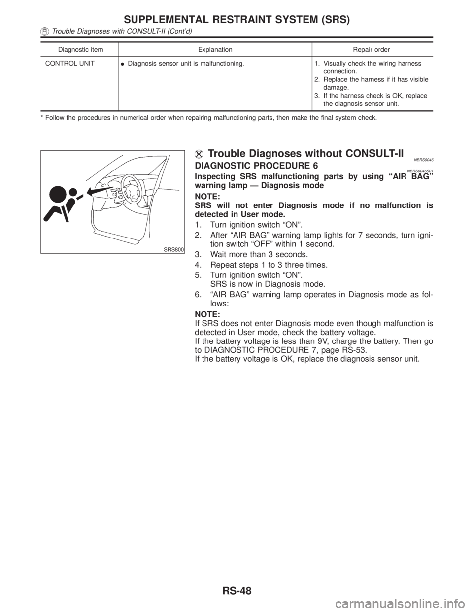
Trouble Diagnoses without CONSULT-IINBRS0046DIAGNOSTIC PROCEDURE 6NBRS0046S01Inspecting SRS malfunctioning parts by using ªAIR BAGº
warning lamp Ð Diagnosis mode
NOTE:
SRS will not enter Diagnosis mode if no malfunction is
detected in User mode.
1. Turn ignition switch ªONº.
2. After ªAIR BAGº warning lamp lights for 7 seconds, turn igni-
tion switch ªOFFº within 1 second.
3. Wait more than 3 seconds.
4. Repeat steps 1 to 3 three times.
5. Turn ignition switch ªONº.
SRS is now in Diagnosis mode.
6. ªAIR BAGº warning lamp operates in Diagnosis mode as fol-
lows:
NOTE:
If SRS does not enter Diagnosis mode even though malfunction is
detected in User mode, check the battery voltage.
If the battery voltage is less than 9V, charge the battery. Then go
to DIAGNOSTIC PROCEDURE 7, page RS-53.
If the battery voltage is OK, replace the diagnosis sensor unit.
SUPPLEMENTAL RESTRAINT SYSTEM (SRS)
Trouble Diagnoses with CONSULT-II (Cont'd)
RS-48
Page 2138 of 2395

No. ªAIR BAGº warning lamp flash pattern Ð Diagnosis mode Ð SRS condition
1
SRS333
athroughbare repeated.IDiagnosis
results (pre-
viously
stored in the
memory)
might not be
erased after
repair.
IIntermittent
malfunction
has been
detected in
the past.
Go to DIAG-
NOSTIC PRO-
CEDURE 8
(RS-55).
2
SRS341
athroughdare repeated.
bÐ Driver and passenger
air bag and seat belt pre-ten-
sioner marker (For identifying
driver air bag, passenger air
bag and/or seat belt pre-ten-
sioners malfunctioning)
dÐ Indicates malfunctioning
part. The number of flash var-
ies with malfunctioning part
(0.5 sec. ON and 0.5 sec.
OFF is counted as one flash.)The system is
malfunctioning
and needs to
be repaired.
3
SRS342-A
athroughfare repeated.
b,c,dÐ Side air bag
marker (For identifying side
air bag malfunctioning)
fÐ Indicates malfunctioning
part. The number of flash var-
ies with malfunctioning part
(0.5 sec. ON and 0.5 sec.
OFF is counted as one flash.)
7. Malfunctioning part is indicated by the number of flashes (part
dorf). Compare the number of flashes to ªAir Bag Warning
Lamp Flash Code Chartº, page RS-50, and locate malfunction-
ing part.
8. Turn ignition switch ªOFFº, and disconnect both battery cables.
9. Repair the system as outlined by the ªRepair orderº in ªWarn-
ing Lamp Flash Code Chartº that corresponds to the flash
code. For replacement procedure of component parts, refer to
RS-15.
10. After repairing the system, go to DIAGNOSTIC PROCEDURE
7, page RS-53.
GI
MA
EM
LC
EC
FE
AT
TF
PD
AX
SU
BR
ST
BT
HA
SC
EL
IDX
SUPPLEMENTAL RESTRAINT SYSTEM (SRS)
Trouble Diagnoses without CONSULT-II (Cont'd)
RS-49
Page 2142 of 2395

The satellite sensor (LH)
is malfunctioning.
(f: 4 flashes)Flash pattern
SRS339-A
athroughfare repeated.
fÐ Four flashes indi-
cate malfunctioning sat-
ellite sensor (LH) circuit.
Repair order (ªRecheck SRS at each replacement.º)
1. Visually check the wiring harness connection.
2. Replace the harness if it has visible damage.
3. Replace the satellite sensor (LH).
4. Replace the diagnosis sensor unit.
5. Replace the related harness.
* Follow the procedures in numerical order when repairing malfunctioning parts. Confirm whether malfunction is eliminated
using the air bag warning lamp or CONSULT-II each time repair is finished. If malfunction is still observed, proceed to the next
step. When malfunction is eliminated, further repair work is not required.
SRS800
DIAGNOSTIC PROCEDURE 7NBRS0046S02Final checking after repairing SRS by using ªAIR BAGº warn-
ing lamp Ð Diagnosis mode and User mode
1. After repairing SRS connect both battery cables.
2. Open driver's door.
3. Turn ignition switch from ªOFFº to ªONº.
4. ªAIR BAGº warning lamp operates in Diagnosis mode as fol-
lows:
GI
MA
EM
LC
EC
FE
AT
TF
PD
AX
SU
BR
ST
BT
HA
SC
EL
IDX
SUPPLEMENTAL RESTRAINT SYSTEM (SRS)
Trouble Diagnoses without CONSULT-II (Cont'd)
RS-53
Page 2152 of 2395

STARTING & CHARGING SYSTEM
SECTION
SC
CONTENTS
PRECAUTIONS...............................................................2
Supplemental Restraint System (SRS)²AIR
BAG²and²SEAT BELT PRE-TENSIONER²...............2
Wiring Diagrams and Trouble Diagnosis .....................2
PREPARATION...............................................................3
Special Service Tool ....................................................3
BATTERY.........................................................................4
How to Handle Battery ................................................4
METHODS OF PREVENTING OVER-DISCHARGE......4
CHECKING ELECTROLYTE LEVEL............................4
SPECIFIC GRAVITY CHECK......................................5
CHARGING THE BATTERY........................................6
Trouble Diagnoses with Battery/Starting/Charging
System Tester ..............................................................7
DIAGNOSTIC RESULT ITEM CHART..........................9
STARTING SYSTEM.....................................................10
System Description ....................................................10
Wiring Diagram - START -......................................... 11
Trouble Diagnoses with Battery/Starting/Charging
System Tester ............................................................12
DIAGNOSTIC RESULT ITEM CHART........................13
WORK FLOW..........................................................14
DIAGNOSTIC PROCEDURE 1..................................15
DIAGNOSTIC PROCEDURE 2..................................17
MINIMUM SPECIFICATION OF CRANKING
VOLTAGE REFERENCING COOLANT
TEMPERATURE
......................................................17
Construction ...............................................................18
Removal and Installation ...........................................18
Pinion/Clutch Check ..................................................18
CHARGING SYSTEM....................................................19
System Description ....................................................19
Wiring Diagram - CHARGE -.....................................20
Trouble Diagnoses with Battery/Starting/Charging
System Tester ............................................................21
DIAGNOSTIC RESULT ITEM CHART........................23
WORK FLOW..........................................................24
DIAGNOSTIC PROCEDURE 1..................................25
DIAGNOSTIC PROCEDURE 2..................................26
DIAGNOSTIC PROCEDURE 3..................................27
MALFUNCTION INDICATOR....................................27
Construction ...............................................................28
Removal and Installation ...........................................28
SERVICE DATA AND SPECIFICATIONS (SDS).........29
Battery........................................................................29
Starter ........................................................................29
Alternator ...................................................................29
GI
MA
EM
LC
EC
FE
AT
TF
PD
AX
SU
BR
ST
RS
BT
HA
EL
IDX
Page 2154 of 2395

Special Service ToolNBSC0017
Tool number
Tool nameDescription
J-44373 Model 620
Battery/Starting/Charging
system tester
SEL403X
GI
MA
EM
LC
EC
FE
AT
TF
PD
AX
SU
BR
ST
RS
BT
HA
EL
IDX
PREPARATION
Special Service Tool
SC-3
Page 2155 of 2395

How to Handle BatteryNBSC0003CAUTION:
IIf it becomes necessary to start the engine with a booster
battery and jumper cables, use a 12-volt booster battery.
IAfter connecting battery cables, ensure that they are
tightly clamped to battery terminals for good contact.
INever add distilled water through the hole used to check
specific gravity.
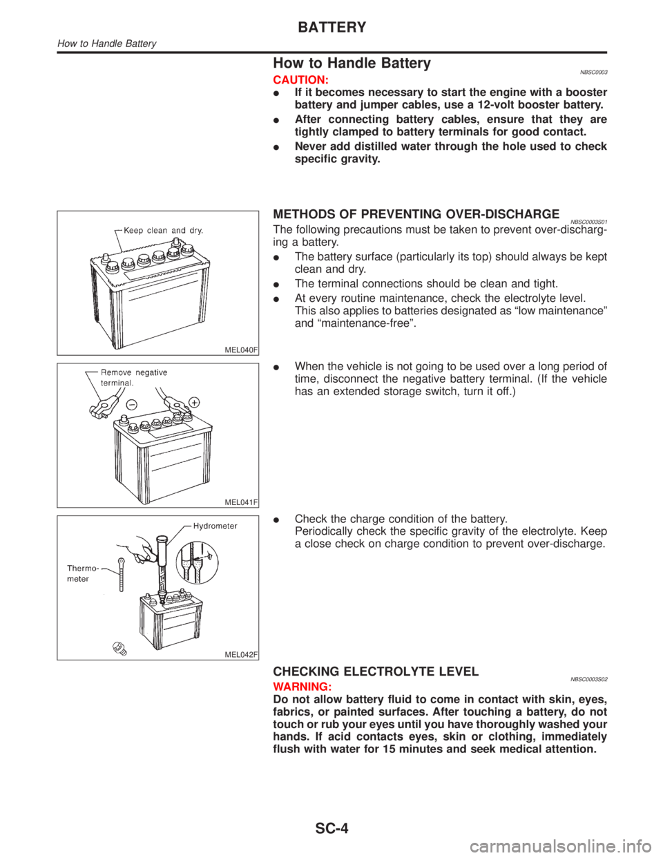
MEL040F
METHODS OF PREVENTING OVER-DISCHARGENBSC0003S01The following precautions must be taken to prevent over-discharg-
ing a battery.
IThe battery surface (particularly its top) should always be kept
clean and dry.
IThe terminal connections should be clean and tight.
IAt every routine maintenance, check the electrolyte level.
This also applies to batteries designated as ªlow maintenanceº
and ªmaintenance-freeº.
MEL041F
IWhen the vehicle is not going to be used over a long period of
time, disconnect the negative battery terminal. (If the vehicle
has an extended storage switch, turn it off.)
MEL042F
ICheck the charge condition of the battery.
Periodically check the specific gravity of the electrolyte. Keep
a close check on charge condition to prevent over-discharge.
CHECKING ELECTROLYTE LEVELNBSC0003S02WARNING:
Do not allow battery fluid to come in contact with skin, eyes,
fabrics, or painted surfaces. After touching a battery, do not
touch or rub your eyes until you have thoroughly washed your
hands. If acid contacts eyes, skin or clothing, immediately
flush with water for 15 minutes and seek medical attention.
BATTERY
How to Handle Battery
SC-4