Ac system INFINITI QX4 2001 Factory Service Manual
[x] Cancel search | Manufacturer: INFINITI, Model Year: 2001, Model line: QX4, Model: INFINITI QX4 2001Pages: 2395, PDF Size: 43.2 MB
Page 936 of 2395

10 CHECK FOR EVAP LEAK
Without CONSULT-II
1. Turn ignition switch ªOFFº.
2. Apply 12 volts DC to EVAP canister vent control valve. The valve will close. (Continue to apply 12 volts until the end of
test.)
SEF598U
3. Apply 12 volts DC to vacuum cut valve bypass valve. The valve will open. (Continue to apply 12V until the end of test.)
SEF599U
4. Pressurize the EVAP line using pressure pump with 1.3 to 2.7 kPa (10 to 20 mmHg, 0.39 to 0.79 inHg), then remove
pump and EVAP service port adapter.
NOTE:
INever use compressed air or a high pressure pump.
IDo not exceed 4.12 kPa (0.042 kg/cm
2, 0.6 psi) of pressure in the system.
5. Using EVAP leak detector, locate the EVAP leak. For the leak detector, refer to the instruction manual for more details.
Refer to ªEVAPORATIVE EMISSION LINE DRAWINGº, EC-36.
SEF200U
OK or NG
OK©GO TO 12.
NG©Repair or replace.
GI
MA
EM
LC
FE
AT
TF
PD
AX
SU
BR
ST
RS
BT
HA
SC
EL
IDX
DTC P0455 EVAP CONTROL SYSTEM (GROSS LEAK)
Diagnostic Procedure (Cont'd)
EC-401
Page 937 of 2395

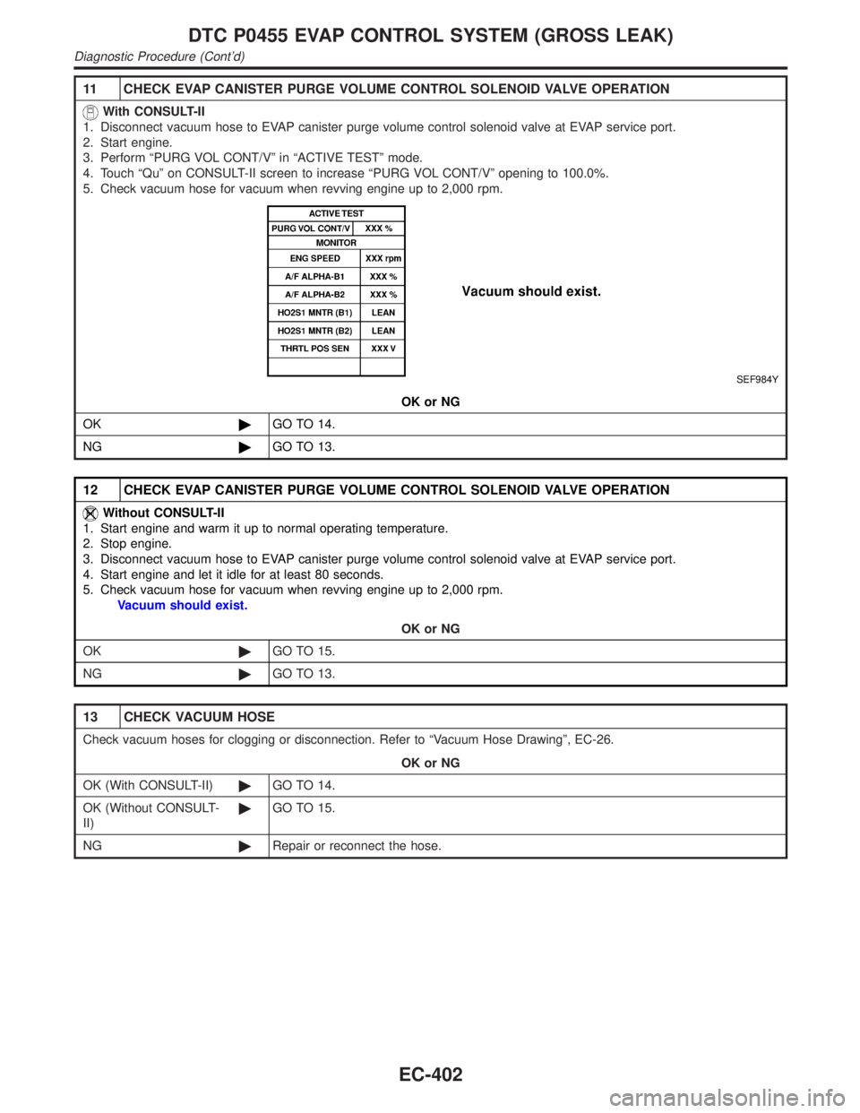
11 CHECK EVAP CANISTER PURGE VOLUME CONTROL SOLENOID VALVE OPERATION
With CONSULT-II
1. Disconnect vacuum hose to EVAP canister purge volume control solenoid valve at EVAP service port.
2. Start engine.
3. Perform ªPURG VOL CONT/Vº in ªACTIVE TESTº mode.
4. Touch ªQuº on CONSULT-II screen to increase ªPURG VOL CONT/Vº opening to 100.0%.
5. Check vacuum hose for vacuum when revving engine up to 2,000 rpm.
SEF984Y
OK or NG
OK©GO TO 14.
NG©GO TO 13.
12 CHECK EVAP CANISTER PURGE VOLUME CONTROL SOLENOID VALVE OPERATION
Without CONSULT-II
1. Start engine and warm it up to normal operating temperature.
2. Stop engine.
3. Disconnect vacuum hose to EVAP canister purge volume control solenoid valve at EVAP service port.
4. Start engine and let it idle for at least 80 seconds.
5. Check vacuum hose for vacuum when revving engine up to 2,000 rpm.
Vacuum should exist.
OK or NG
OK©GO TO 15.
NG©GO TO 13.
13 CHECK VACUUM HOSE
Check vacuum hoses for clogging or disconnection. Refer to ªVacuum Hose Drawingº, EC-26.
OK or NG
OK (With CONSULT-II)©GO TO 14.
OK (Without CONSULT-
II)©GO TO 15.
NG©Repair or reconnect the hose.
DTC P0455 EVAP CONTROL SYSTEM (GROSS LEAK)
Diagnostic Procedure (Cont'd)
EC-402
Page 938 of 2395

14 CHECK EVAP CANISTER PURGE VOLUME CONTROL SOLENOID VALVE
With CONSULT-II
1. Start engine.
2. Perform ªPURG VOL CONT/Vº in ªACTIVE TESTº mode with CONSULT-II. Check that engine speed varies according
to the valve opening.
SEF985Y
OK or NG
OK©GO TO 16.
NG©GO TO 15.
GI
MA
EM
LC
FE
AT
TF
PD
AX
SU
BR
ST
RS
BT
HA
SC
EL
IDX
DTC P0455 EVAP CONTROL SYSTEM (GROSS LEAK)
Diagnostic Procedure (Cont'd)
EC-403
Page 939 of 2395

15 CHECK EVAP CANISTER PURGE VOLUME CONTROL SOLENOID VALVE
With CONSULT-II
Check air passage continuity of EVAP canister purge volume control solenoid valve under the following conditions.
SEF986Y
SEF334X
Without CONSULT-II
Check air passage continuity of EVAP canister purge volume control solenoid valve under the following conditions.
SEF986Y
SEF335X
OK or NG
OK©GO TO 16.
NG©Replace EVAP canister purge volume control solenoid valve.
DTC P0455 EVAP CONTROL SYSTEM (GROSS LEAK)
Diagnostic Procedure (Cont'd)
EC-404
Page 940 of 2395

16 CHECK ABSOLUTE PRESSURE SENSOR
1. Remove absolute pressure sensor with its harness connector connected.
SEF961Y
2. Remove hose from absolute pressure sensor.
3. Install a vacuum pump to absolute pressure sensor.
4. Turn ignition switch ªONº and check output voltage between ECM terminal 80 and engine ground under the following
conditions.
SEF300XA
CAUTION:
IAlways calibrate the vacuum pump gauge when using it.
IDo not apply below þ93.3 kPa (±700 mmHg, ±27.56 inHg) or over 101.3 kPa (760 mmHg, 29.92 inHg) of pressure.
OK or NG
OK©GO TO 17.
NG©Replace absolute pressure sensor.
17 CHECK FUEL TANK TEMPERATURE SENSOR
1. Remove fuel level sensor unit.
2. Check resistance between fuel level sensor unit and fuel pump terminals 4 and 5 by heating with hot water or heat gun
as shown in the figure.
SEF974Y
OK or NG
OK©GO TO 18.
NG©Replace fuel level sensor unit.
GI
MA
EM
LC
FE
AT
TF
PD
AX
SU
BR
ST
RS
BT
HA
SC
EL
IDX
DTC P0455 EVAP CONTROL SYSTEM (GROSS LEAK)
Diagnostic Procedure (Cont'd)
EC-405
Page 941 of 2395

18 CHECK EVAP CONTROL SYSTEM PRESSURE SENSOR
1. Remove EVAP control system pressure sensor with its harness connector connected.
CAUTION:
INever apply force to the air hole protector of the sensor if equipped.
SEF799W
2. Remove hose from EVAP control system pressure sensor.
3. Turn ignition switch ªONº.
4. Use pump to apply vacuum and pressure to EVAP control system pressure sensor as shown in figure.
CAUTION:
IAlways calibrate the vacuum pump gauge when using it.
IDo not apply below þ20 kPa (þ150 mmHg, þ5.91 inHg) or over 20 kPa (150 mmHg, 5.91 inHg) of pressure.
5. Check input voltage between ECM terminal 84 and ground.
SEF342X
CAUTION:
IDiscard and EVAP control system pressure sensor which has been dropped from a height of more than 0.5m
(19.7in) onto a hard surface such as a concrete floor; use a new one.
OK or NG
OK©GO TO 19.
NG©Replace EVAP control system pressure sensor.
19 CHECK INTERMITTENT INCIDENT
Refer to ªTROUBLE DIAGNOSIS FOR INTERMITTENT INCIDENTº, EC-140.
©INSPECTION END
DTC P0455 EVAP CONTROL SYSTEM (GROSS LEAK)
Diagnostic Procedure (Cont'd)
EC-406
Page 957 of 2395

DescriptionNBEC0249SYSTEM DESCRIPTIONNBEC0249S01
Sensor Input Signal to ECMECM func-
tionActuator
Crankshaft position sensor (POS) Engine speed (POS signal)
Idle air
controlIACV-AAC valve Crankshaft position sensor (REF) Engine speed (REF signal)
Mass air flow sensor Amount of intake air
Engine coolant temperature sensor Engine coolant temperature
Ignition switch Start signal
Throttle position sensor Throttle position
Park/neutral position (PNP) switch Park/neutral position
Air conditioner switch Air conditioner operation
Power steering oil pressure switch Power steering load signal
Battery Battery voltage
Vehicle speed sensor Vehicle speed
Ambient air temperature switch Ambient air temperature
Intake air temperature sensor Intake air temperature
Absolute pressure sensor Ambient barometic pressure
This system automatically controls engine idle speed to a specified
level. Idle speed is controlled through fine adjustment of the
amount of air which by-passes the throttle valve via IACV-AAC
valve. The IACV-AAC valve changes the opening of the air by-pass
passage to control the amount of auxiliary air. This valve is actu-
ated by a step motor built into the valve, which moves the valve in
the axial direction in steps corresponding to the ECM output sig-
nals. One step of IACV-AAC valve movement causes the respec-
tive opening of the air by-pass passage. (i.e. when the step
advances, the opening is enlarged.) The opening of the valve is
varied to allow for optimum control of the engine idling speed. The
crankshaft position sensor (POS) detects the actual engine speed
and sends a signal to the ECM. The ECM then controls the step
position of the IACV-AAC valve so that engine speed coincides with
the target value memorized in ECM. The target engine speed is the
lowest speed at which the engine can operate steadily. The opti-
mum value stored in the ECM is determined by takig into consid-
eration various engine conditions, such as during warm up,
deceleration, and engine load (air conditioner, power steering and
cooling fan operation).
SEF765P
COMPONENT DESCRIPTIONNBEC0249S02IACV-AAC ValveNBEC0249S0201The IACV-AAC valve is operated by a step motor for centralized
control of auxiliary air supply. This motor has four winding phases
and is actuated by the output signals of ECM which turns ON and
OFF two windings each in seqeunce. Each time the IACV-AAC
valve opens or closes to change tha auxiliary air quantity, the ECM
sends a pulse signal to the step motor. When no change in the
auxiliary air quantity is needed, the ECM does not issue the pulse
signal. A certain voltage signal is issued so that the valve remains
at that particular opening.
DTC P0505 IDLE AIR CONTROL VALVE (IACV) Ð AUXILIARY AIR CONTROL
(AAC) VALVE
Description
EC-422
Page 965 of 2395

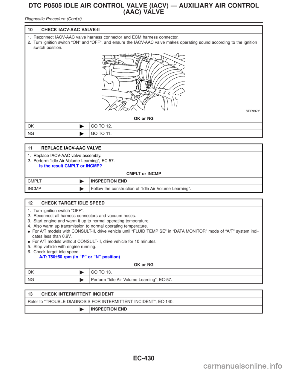
10 CHECK IACV-AAC VALVE-II
1. Reconnect IACV-AAC valve harness connector and ECM harness connector.
2. Turn ignition switch ªONº and ªOFFº, and ensure the IACV-AAC valve makes operating sound according to the ignition
switch position.
SEF997Y
OK or NG
OK©GO TO 12.
NG©GO TO 11.
11 REPLACE IACV-AAC VALVE
1. Replace IACV-AAC valve assembly.
2. Perform ªIdle Air Volume Learningº, EC-57.
Is the result CMPLT or INCMP?
CMPLT or INCMP
CMPLT©INSPECTION END
INCMP©Follow the construction of ªIdle Air Volume Learningº.
12 CHECK TARGET IDLE SPEED
1. Turn ignition switch ªOFFº.
2. Reconnect all harness connectors and vacuum hoses.
3. Start engine and warm it up to normal operating temperature.
4. Also warm up transmission to normal operating temperature.
IFor A/T models with CONSULT-II, drive vehicle until ªFLUID TEMP SEº in ªDATA MONITORº mode of ªA/Tº system indi-
cates less than 0.9V.
IFor A/T models without CONSULT-II, drive vehicle for 10 minutes.
5. Stop vehicle with engine running.
6. Check target idle speed.
A/T: 750±50 rpm (in ªPº or ªNº position)
OK or NG
OK©GO TO 13.
NG©Perform ªIdle Air Volume Learningº, EC-57.
13 CHECK INTERMITTENT INCIDENT
Refer to ªTROUBLE DIAGNOSIS FOR INTERMITTENT INCIDENTº, EC-140.
©INSPECTION END
DTC P0505 IDLE AIR CONTROL VALVE (IACV) Ð AUXILIARY AIR CONTROL
(AAC) VALVE
Diagnostic Procedure (Cont'd)
EC-430
Page 975 of 2395

System DescriptionNBEC0264This circuit line (LAN) is used to control the smooth shifting up and down of A/T during the hard acceleration/
deceleration.
Pulse signals are exchanged between ECM and TCM (Transmission Control Module).
Be sure to erase the malfunction information such as DTC not only in TCM but also ECM after the A/T
related repair.
ECM Terminals and Reference ValueNBEC0672Specification data are reference values and are measured between each terminal and ground.
CAUTION:
Do not use ECM ground terminals when measuring input/output voltage. Doing so may result in dam-
age to the ECM's transistor. Use a ground other than ECM terminals, such as the ground.
TERMI-
NAL
NO.WIRE
COLORITEM CONDITION DATA (DC Voltage)
114 G/RCommunication line
(LAN)[Engine is running]
IIdle speedApproximately 2V
On Board Diagnosis LogicNBEC0266Malfunction is detected when ECM receives incorrect voltage from
TCM (Transmission Control Module) continuously.
Possible CauseNBEC0517IHarness or connectors
[The communication line circuit between ECM and TCM
(Transmission Control Module) is open or shorted.]
ITCM
IDead (Weak) battery
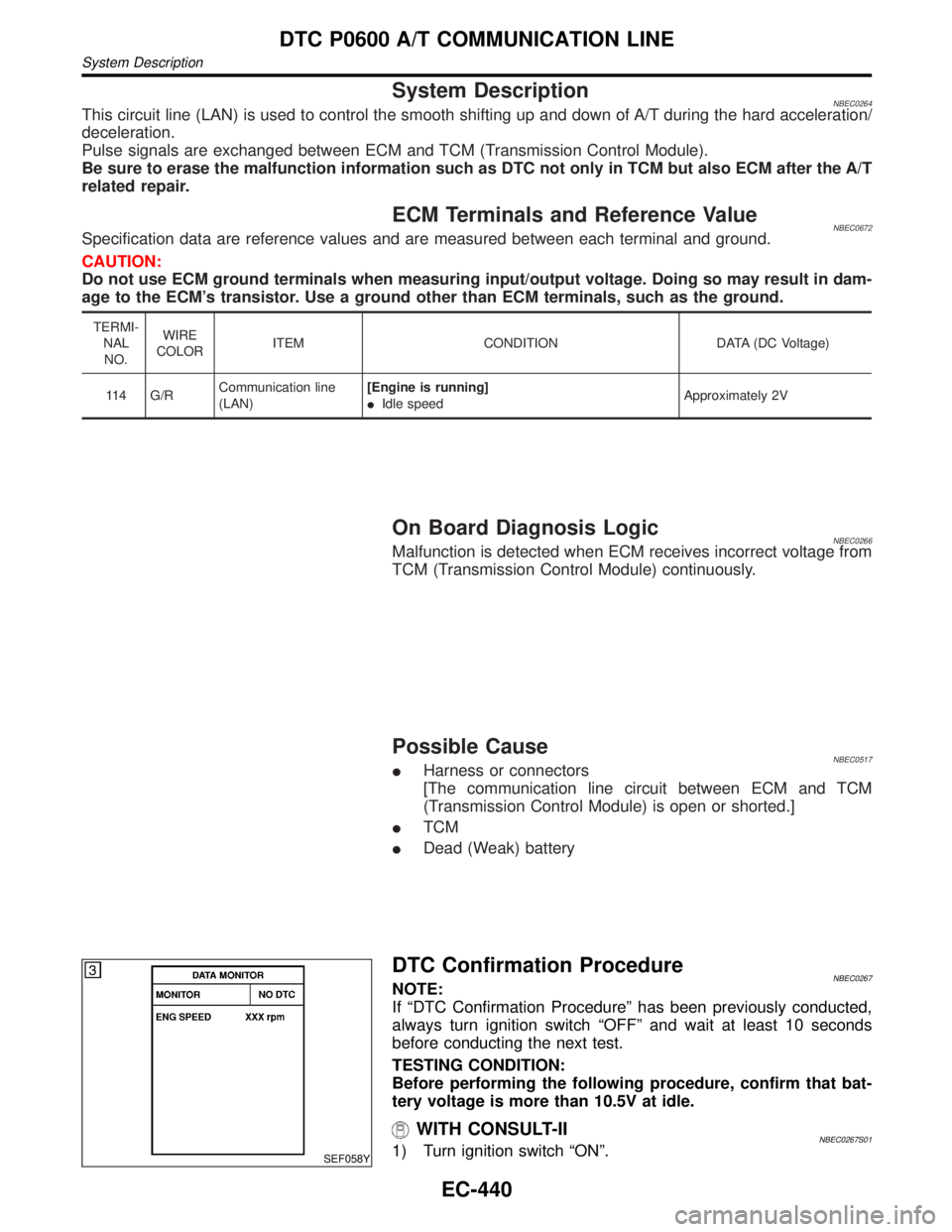
SEF058Y
DTC Confirmation ProcedureNBEC0267NOTE:
If ªDTC Confirmation Procedureº has been previously conducted,
always turn ignition switch ªOFFº and wait at least 10 seconds
before conducting the next test.
TESTING CONDITION:
Before performing the following procedure, confirm that bat-
tery voltage is more than 10.5V at idle.
WITH CONSULT-IINBEC0267S011) Turn ignition switch ªONº.
DTC P0600 A/T COMMUNICATION LINE
System Description
EC-440
Page 980 of 2395

Diagnostic ProcedureNBEC0274
1 INSPECTION START
With CONSULT-II
1. Turn ignition switch ªONº.
2. Select ªSELF DIAG RESULTSº mode with CONSULT-II.
3. Touch ªERASEº.
4.Perform ªDTC Confirmation Procedureº.
See EC-444.
5. Is the 1st trip DTC P0605 displayed again?
With GST
1. Turn ignition switch ªONº.
2. Select MODE 4 with GST.
3. Touch ªERASEº.
4.Perform ªDTC Confirmation Procedureº.
See EC-444.
5. Is the 1st trip DTC P0605 displayed again?
YesorNo
Ye s©GO TO 2.
No©INSPECTION END
2 REPLACE ECM
1. Replace ECM.
2. Perform initialization of NVIS (NATS) system and registration of all NVIS (NATS) ignition key IDs. Refer to ªNVIS (NIS-
SAN VEHICLE IMMOBILIZER SYSTEM Ð NATS)º, EC-74.
3. Perform ªIdle Air Volume Learningº, EC-57,
Is the result CMPLT or INCMP?
CMPLT or INCMP
CMPLT©INSPECTION END
INCMP©Follow the construction of ªIdle Air Volume Learningº.
GI
MA
EM
LC
FE
AT
TF
PD
AX
SU
BR
ST
RS
BT
HA
SC
EL
IDX
DTC P0605 ECM
Diagnostic Procedure
EC-445