IDX INFINITI QX4 2001 Factory Service Manual
[x] Cancel search | Manufacturer: INFINITI, Model Year: 2001, Model line: QX4, Model: INFINITI QX4 2001Pages: 2395, PDF Size: 43.2 MB
Page 526 of 2395

SBF034B
Removal and InstallationNBBT0019
SBT472
SBT473
REMOVALNBBT0019S01After removing moldings, remove glass using piano wire or power
cutting tool and an inflatable pump bag.
WARNING:
When cutting the glass from the vehicle, always wear safety
glasses and heavy gloves to help prevent glass splinters from
entering your eyes or cutting your hands.
CAUTION:
IBe careful not to scratch the glass when removing.
IDo not set or stand the glass on its edge. Small chips may
develop into cracks.
INSTALLATIONNBBT0019S02IUse a genuine Nissan Urethane Adhesive Kit or equivalent
and follow the instructions furnished with it.
IWhile the urethane adhesive is curing, open a door win-
dow. This will prevent the glass from being forced out by
passenger compartment air pressure when a door is
closed.
IThe molding must be installed securely so that it is in
position and leaves no gap.
IInform the customer that the vehicle should remain sta-
tionary until the urethane adhesive has completely cured
(preferably 24 hours). Curing time varies with temperature
and humidity.
WARNING:
IKeep heat and open flames away as primers and adhesive
are flammable.
IThe materials contained in the kit are harmful if
swallowed, and may irritate skin and eyes. Avoid contact
with the skin and eyes.
IUse in an open, well ventilated location. Avoid breathing
the vapors. They can be harmful if inhaled. If affected by
vapor inhalation, immediately move to an area with fresh
air.
IDriving the vehicle before the urethane adhesive has com-
pletely cured may affect the performance of the wind-
shield in case of an accident.
CAUTION:
IDo not use an adhesive which is past its usable term.
Shelf life of this product is limited to six months after the
date of manufacture. Carefully adhere to the expiration or
manufacture date printed on the box.
IKeep primers and adhesive in a cool, dry place. Ideally,
they should be stored in a refrigerator.
IDo not leave primers or adhesive cartridge unattended
with their caps open or off.
IThe vehicle should not be driven for at least 24 hours or
until the urethane adhesive has completely cured. Curing
time varies depending on temperature and humidities. The
curing time will increase under higher temperatures and
lower humidities.
GI
MA
EM
LC
EC
FE
AT
TF
PD
AX
SU
BR
ST
RS
HA
SC
EL
IDX
WINDSHIELD AND WINDOWS
Removal and Installation
BT-53
Page 528 of 2395

REAR SIDE WINDOWNBBT0019S04
SBT359-A
GI
MA
EM
LC
EC
FE
AT
TF
PD
AX
SU
BR
ST
RS
HA
SC
EL
IDX
WINDSHIELD AND WINDOWS
Removal and Installation (Cont'd)
BT-55
Page 530 of 2395

AlignmentNBBT0021IAll dimensions indicated in figures are actual ones.
IWhen using a tracking gauge, adjust both pointers to equal length. Then check the pointers and gauge
itself to make sure there is no free play.
IWhen a measuring tape is used, check to be sure there is no elongation, twisting or bending.
IMeasurements should be taken at the center of the mounting holes.
IAn asterisk (H) following the value at the measuring point indicates that the measuring point on the other
side is symmetrically the same value.
IThe coordinates of the measurement points are the distances measured from the standard line of ªXº, ªYº
and ªZº.
SBF874GD
GI
MA
EM
LC
EC
FE
AT
TF
PD
AX
SU
BR
ST
RS
HA
SC
EL
IDX
BODY (ALIGNMENT)
Alignment
BT-57
Page 532 of 2395

Measurement PointsNBBT0021S0102
SBT195
GI
MA
EM
LC
EC
FE
AT
TF
PD
AX
SU
BR
ST
RS
HA
SC
EL
IDX
BODY (ALIGNMENT)
Alignment (Cont'd)
BT-59
Page 534 of 2395

Measurement PointsNBBT0021S0202
SBT361
GI
MA
EM
LC
EC
FE
AT
TF
PD
AX
SU
BR
ST
RS
HA
SC
EL
IDX
BODY (ALIGNMENT)
Alignment (Cont'd)
BT-61
Page 536 of 2395

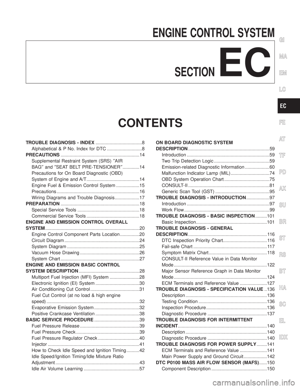
ENGINE CONTROL SYSTEM
SECTION
EC
CONTENTS
TROUBLE DIAGNOSIS - INDEX....................................8
Alphabetical & P No. Index for DTC ...........................8
PRECAUTIONS.............................................................14
Supplemental Restraint System (SRS)²AIR
BAG²and²SEAT BELT PRE-TENSIONER².............14
Precautions for On Board Diagnostic (OBD)
System of Engine and A/T.........................................14
Engine Fuel & Emission Control System ..................15
Precautions ................................................................16
Wiring Diagrams and Trouble Diagnosis ...................17
PREPARATION.............................................................18
Special Service Tools ................................................18
Commercial Service Tools .........................................18
ENGINE AND EMISSION CONTROL OVERALL
SYSTEM.........................................................................20
Engine Control Component Parts Location ...............20
Circuit Diagram ..........................................................24
System Diagram ........................................................25
Vacuum Hose Drawing ..............................................26
System Chart .............................................................27
ENGINE AND EMISSION BASIC CONTROL
SYSTEM DESCRIPTION...............................................28
Multiport Fuel Injection (MFI) System .......................28
Electronic Ignition (EI) System ..................................30
Air Conditioning Cut Control ......................................31
Fuel Cut Control (at no load & high engine
speed) ........................................................................32
Evaporative Emission System ...................................32
Positive Crankcase Ventilation ..................................38
BASIC SERVICE PROCEDURE...................................39
Fuel Pressure Release ..............................................39
Fuel Pressure Check .................................................39
Fuel Pressure Regulator Check ................................40
Injector .......................................................................41
How to Check Idle Speed and Ignition Timing ..........42
Idle Speed/Ignition Timing/Idle Mixture Ratio
Adjustment .................................................................43
Idle Air Volume Learning ...........................................57ON BOARD DIAGNOSTIC SYSTEM
DESCRIPTION...............................................................59
Introduction ................................................................59
Two Trip Detection Logic ...........................................59
Emission-related Diagnostic Information ...................60
Malfunction Indicator Lamp (MIL) ..............................74
OBD System Operation Chart ...................................75
CONSULT-II ...............................................................81
Generic Scan Tool (GST) ..........................................95
TROUBLE DIAGNOSIS - INTRODUCTION..................97
Introduction ................................................................97
Work Flow ..................................................................99
TROUBLE DIAGNOSIS - BASIC INSPECTION.........101
Basic Inspection.......................................................101
TROUBLE DIAGNOSIS - GENERAL
DESCRIPTION............................................................. 116
DTC Inspection Priority Chart.................................. 116
Fail-safe Chart ......................................................... 117
Symptom Matrix Chart ............................................. 118
CONSULT-II Reference Value in Data Monitor
Mode ........................................................................122
Major Sensor Reference Graph in Data Monitor
Mode ........................................................................124
ECM Terminals and Reference Value .....................127
TROUBLE DIAGNOSIS - SPECIFICATION VALUE..136
Description ...............................................................136
Testing Condition .....................................................136
Inspection Procedure ...............................................136
Diagnostic Procedure ..............................................137
TROUBLE DIAGNOSIS FOR INTERMITTENT
INCIDENT.....................................................................140
Description ...............................................................140
Diagnostic Procedure ..............................................140
TROUBLE DIAGNOSIS FOR POWER SUPPLY........141
ECM Terminals and Reference Value .....................141
Main Power Supply and Ground Circuit ..................142
DTC P0100 MASS AIR FLOW SENSOR (MAFS)......150
Component Description ...........................................150
GI
MA
EM
LC
FE
AT
TF
PD
AX
SU
BR
ST
RS
BT
HA
SC
EL
IDX
Page 538 of 2395

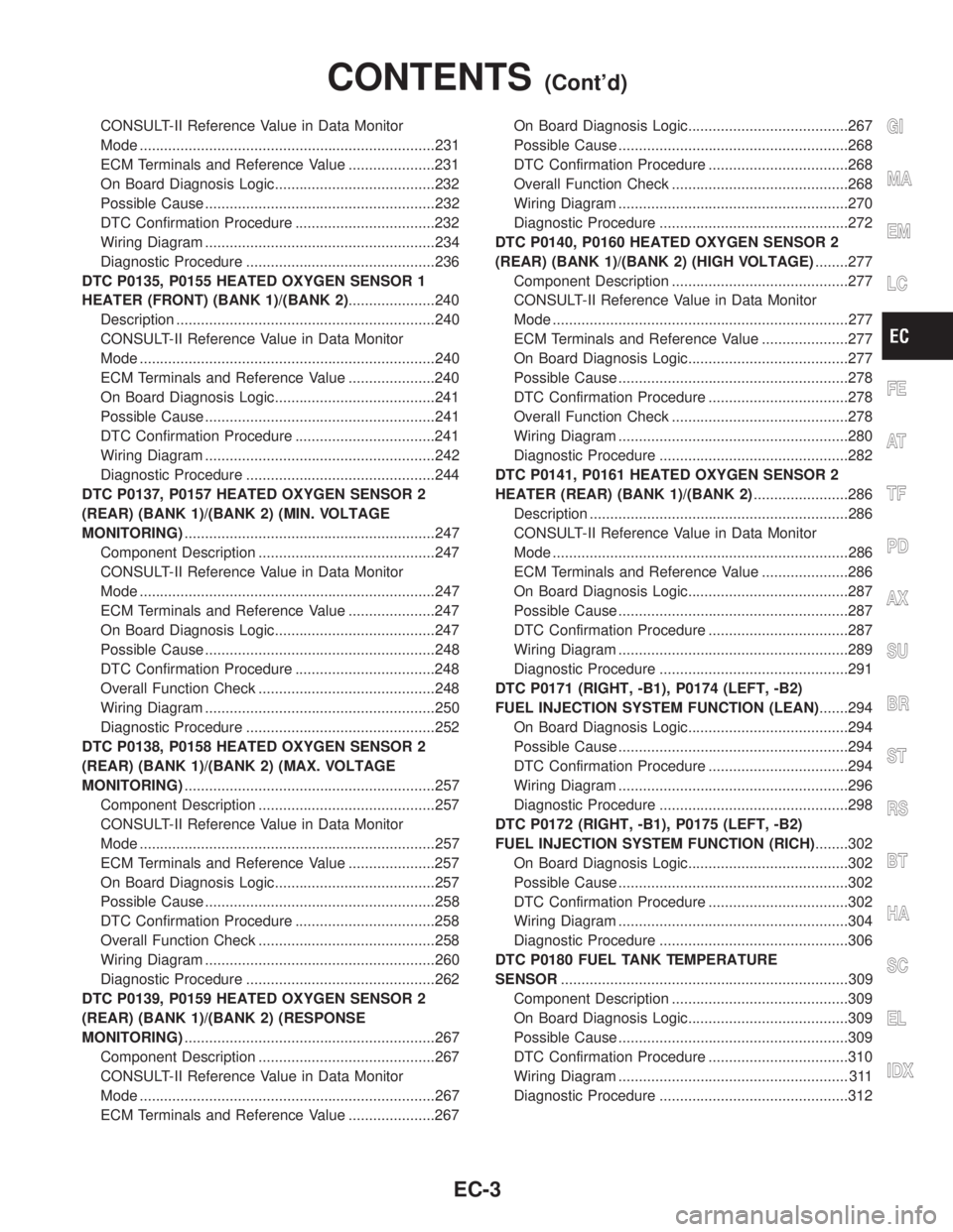
CONSULT-II Reference Value in Data Monitor
Mode ........................................................................231
ECM Terminals and Reference Value .....................231
On Board Diagnosis Logic.......................................232
Possible Cause ........................................................232
DTC Confirmation Procedure ..................................232
Wiring Diagram ........................................................234
Diagnostic Procedure ..............................................236
DTC P0135, P0155 HEATED OXYGEN SENSOR 1
HEATER (FRONT) (BANK 1)/(BANK 2).....................240
Description ...............................................................240
CONSULT-II Reference Value in Data Monitor
Mode ........................................................................240
ECM Terminals and Reference Value .....................240
On Board Diagnosis Logic.......................................241
Possible Cause ........................................................241
DTC Confirmation Procedure ..................................241
Wiring Diagram ........................................................242
Diagnostic Procedure ..............................................244
DTC P0137, P0157 HEATED OXYGEN SENSOR 2
(REAR) (BANK 1)/(BANK 2) (MIN. VOLTAGE
MONITORING).............................................................247
Component Description ...........................................247
CONSULT-II Reference Value in Data Monitor
Mode ........................................................................247
ECM Terminals and Reference Value .....................247
On Board Diagnosis Logic.......................................247
Possible Cause ........................................................248
DTC Confirmation Procedure ..................................248
Overall Function Check ...........................................248
Wiring Diagram ........................................................250
Diagnostic Procedure ..............................................252
DTC P0138, P0158 HEATED OXYGEN SENSOR 2
(REAR) (BANK 1)/(BANK 2) (MAX. VOLTAGE
MONITORING).............................................................257
Component Description ...........................................257
CONSULT-II Reference Value in Data Monitor
Mode ........................................................................257
ECM Terminals and Reference Value .....................257
On Board Diagnosis Logic.......................................257
Possible Cause ........................................................258
DTC Confirmation Procedure ..................................258
Overall Function Check ...........................................258
Wiring Diagram ........................................................260
Diagnostic Procedure ..............................................262
DTC P0139, P0159 HEATED OXYGEN SENSOR 2
(REAR) (BANK 1)/(BANK 2) (RESPONSE
MONITORING).............................................................267
Component Description ...........................................267
CONSULT-II Reference Value in Data Monitor
Mode ........................................................................267
ECM Terminals and Reference Value .....................267On Board Diagnosis Logic.......................................267
Possible Cause ........................................................268
DTC Confirmation Procedure ..................................268
Overall Function Check ...........................................268
Wiring Diagram ........................................................270
Diagnostic Procedure ..............................................272
DTC P0140, P0160 HEATED OXYGEN SENSOR 2
(REAR) (BANK 1)/(BANK 2) (HIGH VOLTAGE)........277
Component Description ...........................................277
CONSULT-II Reference Value in Data Monitor
Mode ........................................................................277
ECM Terminals and Reference Value .....................277
On Board Diagnosis Logic.......................................277
Possible Cause ........................................................278
DTC Confirmation Procedure ..................................278
Overall Function Check ...........................................278
Wiring Diagram ........................................................280
Diagnostic Procedure ..............................................282
DTC P0141, P0161 HEATED OXYGEN SENSOR 2
HEATER (REAR) (BANK 1)/(BANK 2).......................286
Description ...............................................................286
CONSULT-II Reference Value in Data Monitor
Mode ........................................................................286
ECM Terminals and Reference Value .....................286
On Board Diagnosis Logic.......................................287
Possible Cause ........................................................287
DTC Confirmation Procedure ..................................287
Wiring Diagram ........................................................289
Diagnostic Procedure ..............................................291
DTC P0171 (RIGHT, -B1), P0174 (LEFT, -B2)
FUEL INJECTION SYSTEM FUNCTION (LEAN).......294
On Board Diagnosis Logic.......................................294
Possible Cause ........................................................294
DTC Confirmation Procedure ..................................294
Wiring Diagram ........................................................296
Diagnostic Procedure ..............................................298
DTC P0172 (RIGHT, -B1), P0175 (LEFT, -B2)
FUEL INJECTION SYSTEM FUNCTION (RICH)........302
On Board Diagnosis Logic.......................................302
Possible Cause ........................................................302
DTC Confirmation Procedure ..................................302
Wiring Diagram ........................................................304
Diagnostic Procedure ..............................................306
DTC P0180 FUEL TANK TEMPERATURE
SENSOR......................................................................309
Component Description ...........................................309
On Board Diagnosis Logic.......................................309
Possible Cause ........................................................309
DTC Confirmation Procedure ..................................310
Wiring Diagram ........................................................ 311
Diagnostic Procedure ..............................................312GI
MA
EM
LC
FE
AT
TF
PD
AX
SU
BR
ST
RS
BT
HA
SC
EL
IDX
CONTENTS(Cont'd)
EC-3
Page 540 of 2395

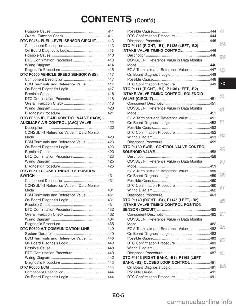
Possible Cause ........................................................ 411
Overall Function Check ........................................... 411
DTC P0464 FUEL LEVEL SENSOR CIRCUIT...........413
Component Description ...........................................413
On Board Diagnostic Logic......................................413
Possible Cause ........................................................413
DTC Confirmation Procedure ..................................413
Wiring Diagram ........................................................414
Diagnostic Procedure ..............................................415
DTC P0500 VEHICLE SPEED SENSOR (VSS).........417
Component Description ...........................................417
ECM Terminals and Reference Value .....................417
On Board Diagnosis Logic.......................................417
Possible Cause ........................................................418
DTC Confirmation Procedure ..................................418
Overall Function Check ...........................................418
Wiring Diagram ........................................................420
Diagnostic Procedure ..............................................421
DTC P0505 IDLE AIR CONTROL VALVE (IACV) -
AUXILIARY AIR CONTROL (AAC) VALVE...............422
Description ...............................................................422
CONSULT-II Reference Value in Data Monitor
Mode ........................................................................423
ECM Terminals and Reference Value .....................423
On Board Diagnosis Logic.......................................423
Possible Cause ........................................................423
DTC Confirmation Procedure ..................................423
Wiring Diagram ........................................................425
Diagnostic Procedure ..............................................426
DTC P0510 CLOSED THROTTLE POSITION
SWITCH.......................................................................431
Component Description ...........................................431
CONSULT-II Reference Value in Data Monitor
Mode ........................................................................431
ECM Terminals and Reference Value .....................431
On Board Diagnosis Logic.......................................431
Possible Cause ........................................................431
DTC Confirmation Procedure ..................................432
Overall Function Check ...........................................432
Wiring Diagram ........................................................434
Diagnostic Procedure ..............................................435
DTC P0600 A/T COMMUNICATION LINE..................440
System Description ..................................................440
ECM Terminals and Reference Value .....................440
On Board Diagnosis Logic.......................................440
Possible Cause ........................................................440
DTC Confirmation Procedure ..................................440
Wiring Diagram ........................................................442
Diagnostic Procedure ..............................................443
DTC P0605 ECM.........................................................444
Component Description ...........................................444
On Board Diagnosis Logic.......................................444Possible Cause ........................................................444
DTC Confirmation Procedure ..................................444
Diagnostic Procedure ..............................................445
DTC P1110 (RIGHT, -B1), P1135 (LEFT, -B2)
INTAKE VALVE TIMING CONTROL..........................446
Description ...............................................................446
CONSULT-II Reference Value in Data Monitor
Mode ........................................................................446
ECM Terminals and Reference Value .....................447
On Board Diagnosis Logic.......................................448
Possible Cause ........................................................448
DTC Confirmation Procedure ..................................449
D T C P 1111(RIGHT, -B1), P1136 (LEFT, -B2)
INTAKE VALVE TIMING CONTROL SOLENOID
VALVE (CIRCUIT)........................................................451
Component Description ...........................................451
CONSULT-II Reference Value in Data Monitor
Mode ........................................................................451
ECM Terminals and Reference Value .....................451
On Board Diagnosis Logic.......................................452
Possible Cause ........................................................452
DTC Confirmation Procedure ..................................452
Wiring Diagram ........................................................453
Diagnostic Procedure ..............................................455
DTC P1130 SWIRL CONTROL VALVE CONTROL
SOLENOID VALVE......................................................458
Description ...............................................................458
CONSULT-II Reference Value in Data Monitor
Mode ........................................................................459
ECM Terminals and Reference Value .....................459
On Board Diagnosis Logic.......................................459
Possible Cause ........................................................460
DTC Confirmation Procedure ..................................460
Wiring Diagram ........................................................462
Diagnostic Procedure ..............................................463
DTC P1140 (RIGHT, -B1), P1145 (LEFT, -B2)
INTAKE VALVE TIMING CONTROL POSITION
SENSOR (CIRCUIT)....................................................482
Component Description ...........................................482
CONSULT-II Reference Value in Data Monitor
Mode ........................................................................482
ECM Terminals and Reference Value .....................482
On Board Diagnosis Logic.......................................483
Possible Cause ........................................................483
DTC Confirmation Procedure ..................................483
Wiring Diagram ........................................................485
Diagnostic Procedure ..............................................487
DTC P1148 (RIGHT BANK, -B1), P1168 (LEFT
BANK, -B2) CLOSED LOOP CONTROL...................491
On Board Diagnosis Logic.......................................491
Possible Cause ........................................................491
DTC Confirmation Procedure ..................................491GI
MA
EM
LC
FE
AT
TF
PD
AX
SU
BR
ST
RS
BT
HA
SC
EL
IDX
CONTENTS(Cont'd)
EC-5
Page 542 of 2395

CONSULT-II Reference Value in Data Monitor
Mode ........................................................................585
ECM Terminals and Reference Value .....................585
On Board Diagnosis Logic.......................................586
Possible Cause ........................................................586
DTC Confirmation Procedure ..................................586
Wiring Diagram ........................................................587
Diagnostic Procedure ..............................................588
DTC P1491 VACUUM CUT VALVE BYPASS
VALVE..........................................................................591
Description ...............................................................591
CONSULT-II Reference Value in Data Monitor
Mode ........................................................................591
ECM Terminals and Reference Value .....................591
On Board Diagnosis Logic.......................................592
Possible Cause ........................................................592
DTC Confirmation Procedure ..................................592
Overall Function Check ...........................................593
Wiring Diagram ........................................................594
Diagnostic Procedure ..............................................595
DTC P1605 A/T DIAGNOSIS COMMUNICATION
LINE.............................................................................603
Component Description ...........................................603
On Board Diagnosis Logic.......................................603
Possible Cause ........................................................603
DTC Confirmation Procedure ..................................603
DTC P1706 PARK/NEUTRAL POSITION (PNP)
SWITCH.......................................................................604
Component Description ...........................................604
CONSULT-II Reference Value in Data Monitor
Mode ........................................................................604
ECM Terminals and Reference Value .....................604
On Board Diagnosis Logic.......................................604
Possible Cause ........................................................604
DTC Confirmation Procedure ..................................605
Overall Function Check ...........................................606
Wiring Diagram ........................................................607
Diagnostic Procedure ..............................................608
VARIABLE INDUCTION AIR CONTROL SYSTEM
(VIAS)...........................................................................610
Description ...............................................................610
ECM Terminals and Reference Value ..................... 611
Wiring Diagram ........................................................612
Diagnostic Procedure ..............................................613
INJECTOR...................................................................616
Component Description ...........................................616
CONSULT-II Reference Value in Data Monitor
Mode ........................................................................616
ECM Terminals and Reference Value .....................616
Wiring Diagram ........................................................617Diagnostic Procedure ..............................................618
START SIGNAL...........................................................621
CONSULT-II Reference Value in Data Monitor
Mode ........................................................................621
ECM Terminals and Reference Value .....................621
Wiring Diagram ........................................................622
Diagnostic Procedure ..............................................623
FUEL PUMP.................................................................625
System Description ..................................................625
Component Description ...........................................625
CONSULT-II Reference Value in Data Monitor
Mode ........................................................................625
ECM Terminals and Reference Value .....................626
Wiring Diagram ........................................................627
Diagnostic Procedure ..............................................628
POWER STEERING OIL PRESSURE SWITCH.........634
Component Description ...........................................634
CONSULT-II Reference Value in Data Monitor
Mode ........................................................................634
ECM Terminals and Reference Value .....................634
Wiring Diagram ........................................................635
Diagnostic Procedure ..............................................636
REFRIGERANT PRESSURE SENSOR......................639
Description ...............................................................639
ECM Terminals and Reference Value .....................639
Wiring Diagram ........................................................640
Diagnostic Procedure ..............................................641
ELECTRICAL LOAD SIGNAL.....................................643
ECM Terminals and Reference Value .....................643
Wiring Diagram ........................................................644
Diagnostic Procedure ..............................................645
MIL & DATA LINK CONNECTORS............................648
Wiring Diagram ........................................................648
SERVICE DATA AND SPECIFICATIONS (SDS).......649
Fuel Pressure Regulator..........................................649
Idle Speed and Ignition Timing ................................649
Mass Air Flow Sensor..............................................649
Engine Coolant Temperature Sensor ......................649
Heated Oxygen Sensor 1 Heater (Front) ................649
Fuel Pump ...............................................................649
IACV-AAC Valve ......................................................649
Injector .....................................................................649
Resistor ....................................................................649
Throttle Position Sensor ..........................................650
Calculated Load Value.............................................650
Intake Air Temperature Sensor ................................650
Heated Oxygen Sensor 2 Heater (Rear).................650
Crankshaft Position Sensor (REF) ..........................650
Fuel Tank Temperature Sensor ...............................650
Camshaft Position Sensor (PHASE) .......................650GI
MA
EM
LC
FE
AT
TF
PD
AX
SU
BR
ST
RS
BT
HA
SC
EL
IDX
CONTENTS(Cont'd)
EC-7
Page 544 of 2395

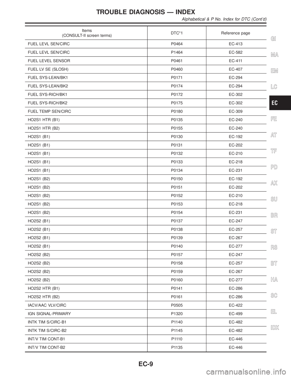
Items
(CONSULT-II screen terms)DTC*1 Reference page
FUEL LEVL SEN/CIRC P0464 EC-413
FUEL LEVL SEN/CIRC P1464 EC-582
FUEL LEVEL SENSOR P0461 EC-411
FUEL LV SE (SLOSH) P0460 EC-407
FUEL SYS-LEAN/BK1 P0171 EC-294
FUEL SYS-LEAN/BK2 P0174 EC-294
FUEL SYS-RICH/BK1 P0172 EC-302
FUEL SYS-RICH/BK2 P0175 EC-302
FUEL TEMP SEN/CIRC P0180 EC-309
HO2S1 HTR (B1) P0135 EC-240
HO2S1 HTR (B2) P0155 EC-240
HO2S1 (B1) P0130 EC-192
HO2S1 (B1) P0131 EC-202
HO2S1 (B1) P0132 EC-210
HO2S1 (B1) P0133 EC-218
HO2S1 (B1) P0134 EC-231
HO2S1 (B2) P0150 EC-192
HO2S1 (B2) P0151 EC-202
HO2S1 (B2) P0152 EC-210
HO2S1 (B2) P0153 EC-218
HO2S1 (B2) P0154 EC-231
HO2S2 (B1) P0137 EC-247
HO2S2 (B1) P0138 EC-257
HO2S2 (B1) P0139 EC-267
HO2S2 (B1) P0140 EC-277
HO2S2 (B2) P0157 EC-247
HO2S2 (B2) P0158 EC-257
HO2S2 (B2) P0159 EC-267
HO2S2 (B2) P0160 EC-277
HO2S2 HTR (B1) P0141 EC-286
HO2S2 HTR (B2) P0161 EC-286
IACV/AAC VLV/CIRC P0505 EC-422
IGN SIGNAL-PRIMARY P1320 EC-499
INTK TIM S/CIRC-B1 P1140 EC-482
INTK TIM S/CIRC-B2 P1145 EC-482
INT/V TIM CONT-B1 P1110 EC-446
INT/V TIM CONT-B2 P1135 EC-446
GI
MA
EM
LC
FE
AT
TF
PD
AX
SU
BR
ST
RS
BT
HA
SC
EL
IDX
TROUBLE DIAGNOSIS Ð INDEX
Alphabetical & P No. Index for DTC (Cont'd)
EC-9