elec INFINITI QX4 2001 Factory Service Manual
[x] Cancel search | Manufacturer: INFINITI, Model Year: 2001, Model line: QX4, Model: INFINITI QX4 2001Pages: 2395, PDF Size: 43.2 MB
Page 1078 of 2395

DTC Confirmation ProcedureNBEC0323NOTE:
If ªDTC Confirmation Procedureº has been previously conducted,
always turn ignition switch ªOFFº and wait at least 10 seconds
before conducting the next test.
TESTING CONDITION:
Always perform test at a temperature of 0ÉC (32ÉF) or more.
SEF205Y
SEF206Y
SEF237Y
WITH CONSULT-IINBEC0323S011) Start engine and warm it up to normal operating temperature.
2) Turn ignition switch ªOFFº and wait at least 10 seconds.
3) Turn ignition switch ªONº.
4) Select ªPURG VOL CN/V P1444º of ªEVAPORATIVE SYS-
TEMº in ªDTC WORK SUPPORTº mode with CONSULT-II.
5) Touch ªSTARTº.
6) Start engine and let it idle until ªTESTINGº on CONSULT-II
changes to ªCOMPLETEDº. (It will take for approximately 10
seconds.)
If ªTESTINGº is not displayed after 5 minutes, retry from
step 2.
7) Make sure that ªOKº is displayed after touching ªSELF-DIAG
RESULTSº. If ªNGº is displayed, refer to ªDiagnostic
Procedureº, EC-545.
WITH GSTNBEC0323S021) Start engine and warm it up to normal operating temperature.
2) Turn ignition switch ªOFFº and wait at least 10 seconds.
3) Start engine and let it idle for at least 20 seconds.
4) Select ªMODE 7º with GST.
5) If 1st trip DTC is detected, go to ªDiagnostic Procedureº,
EC-545.
GI
MA
EM
LC
FE
AT
TF
PD
AX
SU
BR
ST
RS
BT
HA
SC
EL
IDX
DTC P1444 EVAP CANISTER PURGE VOLUME CONTROL SOLENOID VALVE
DTC Confirmation Procedure
EC-543
Page 1089 of 2395

Possible CauseNBEC0589IEVAP canister vent control valve
IEVAP control system pressure sensor and the circuit
IBlocked rubber tube to EVAP canister vent control valve
IWater separator
IEVAP canister is saturated with water.
SEF201Y
DTC Confirmation ProcedureNBEC0330CAUTION:
Always drive vehicle at a safe speed.
NOTE:
If ªDTC Confirmation Procedureº has been previously conducted,
always turn ignition switch ªOFFº and wait at least 10 seconds
before conducting the next test.
WITH CONSULT-IINBEC0330S011) Turn ignition switch ªONº.
2) Select ªDATA MONITORº mode with CONSULT-II.
3) Start engine.
4) Drive vehicle at a speed of approximately 80 km/h (50 MPH)
for a maximum of 15 minutes.
NOTE:
If a malfunction exists, NG result may be displayed quicker.
5) If 1st trip DTC is detected, go to ªDiagnostic Procedureº,
EC-556.
WITH GSTNBEC0330S02Follow the procedure ªWITH CONSULT-IIº above.
DTC P1446 EVAPORATIVE EMISSION (EVAP) CANISTER VENT CONTROL
VALVE (CLOSE)
Possible Cause
EC-554
Page 1097 of 2395

IEVAP canister vent control valve
SEF207Y
SEF208Y
SEF238Y
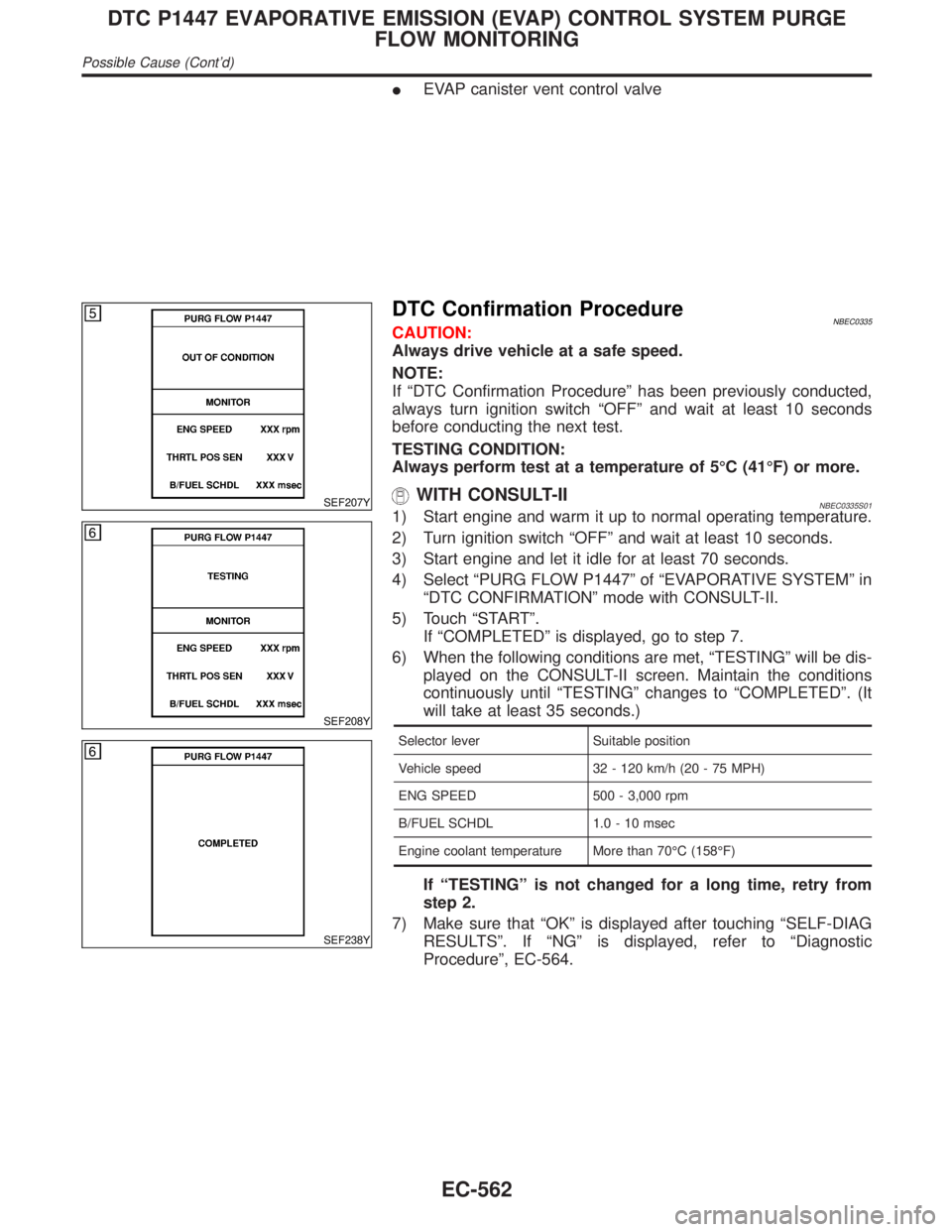
DTC Confirmation ProcedureNBEC0335CAUTION:
Always drive vehicle at a safe speed.
NOTE:
If ªDTC Confirmation Procedureº has been previously conducted,
always turn ignition switch ªOFFº and wait at least 10 seconds
before conducting the next test.
TESTING CONDITION:
Always perform test at a temperature of 5ÉC (41ÉF) or more.
WITH CONSULT-IINBEC0335S011) Start engine and warm it up to normal operating temperature.
2) Turn ignition switch ªOFFº and wait at least 10 seconds.
3) Start engine and let it idle for at least 70 seconds.
4) Select ªPURG FLOW P1447º of ªEVAPORATIVE SYSTEMº in
ªDTC CONFIRMATIONº mode with CONSULT-II.
5) Touch ªSTARTº.
If ªCOMPLETEDº is displayed, go to step 7.
6) When the following conditions are met, ªTESTINGº will be dis-
played on the CONSULT-II screen. Maintain the conditions
continuously until ªTESTINGº changes to ªCOMPLETEDº. (It
will take at least 35 seconds.)
Selector lever Suitable position
Vehicle speed 32 - 120 km/h (20 - 75 MPH)
ENG SPEED 500 - 3,000 rpm
B/FUEL SCHDL 1.0 - 10 msec
Engine coolant temperature More than 70ÉC (158ÉF)
If ªTESTINGº is not changed for a long time, retry from
step 2.
7) Make sure that ªOKº is displayed after touching ªSELF-DIAG
RESULTSº. If ªNGº is displayed, refer to ªDiagnostic
Procedureº, EC-564.
DTC P1447 EVAPORATIVE EMISSION (EVAP) CONTROL SYSTEM PURGE
FLOW MONITORING
Possible Cause (Cont'd)
EC-562
Page 1099 of 2395

Diagnostic Procedure=NBEC0337
1 CHECK EVAP CANISTER
1. Turn ignition switch ªOFFº.
2. Check EVAP canister for cracks.
OK or NG
OK (With CONSULT-II)©GO TO 2.
OK (Without CONSULT-
II)©GO TO 3.
NG©Replace EVAP canister.
2 CHECK PURGE FLOW
With CONSULT-II
1. Disconnect vacuum hose connected to EVAP canister purge volume control solenoid valve at EVAP service port and
install vacuum gauge.
SEF983Y
2. Start engine and let it idle.
3. Select ªPURG VOL CONT/Vº in ªACTIVE TESTº mode with CONSULT-II.
4. Rev engine up to 2,000 rpm.
5. Touch ªQdº and ªQuº on CONSULT-II screen to adjust ªPURG VOL CONT/Vº opening and check vacuum existence.
SEF012Z
OK or NG
OK©GO TO 7.
NG©GO TO 4.
DTC P1447 EVAPORATIVE EMISSION (EVAP) CONTROL SYSTEM PURGE
FLOW MONITORING
Diagnostic Procedure
EC-564
Page 1105 of 2395

15 CHECK THROTTLE POSITION SWITCH
With CONSULT-II
1. Install all removed parts.
2. Start engine and warm it up to normal operating temperature.
3. Turn ignition switch ªOFFº.
4. Remove vacuum hose connected to throttle opener.
5. Connect suitable vacuum hose to vacuum pump and the throttle opener.
6. Apply vacuum [more than þ40.0 kPa (þ300 mmHg, þ11.81 inHg)] until the throttle drum becomes free from the rod of
the throttle opener.
SEF793W
7. Turn ignition switch ªONº.
8. Select ªDATA MONITORº mode with CONSULT-II.
9. Check indication of ªCLSD THL/P SWº under the following conditions.
Measurement must be made with throttle position switch installed in vehicle.
MTBL0355
OK or NG
OK©GO TO 18.
NG©GO TO 17.
DTC P1447 EVAPORATIVE EMISSION (EVAP) CONTROL SYSTEM PURGE
FLOW MONITORING
Diagnostic Procedure (Cont'd)
EC-570
Page 1109 of 2395

Possible CauseNBEC0591IEVAP canister vent control valve
IEVAP control system pressure sensor and circuit
IBlocked rubber tube to EVAP canister vent control valve
IWater separator
IEVAP canister is saturated with water.
IVacuum cut valve
DTC Confirmation ProcedureNBEC0342NOTE:
IIf DTC P1448 is displayed with P0440 or P1440, perform
trouble diagnosis for DTC P1448 first.
IIf ªDTC Confirmation Procedureº has been previously
conducted, always turn ignition switch ªOFFº and wait at least
10 seconds before conducting the next test.
SEF565X
SEF566X
SEF567X
WITH CONSULT-IINBEC0342S01TESTING CONDITION:
IPerform ªDTC WORK SUPPORTº when the fuel level is
between 1/4 to 3/4 full and vehicle is placed on flat level
surface.
IOpen engine hood before conducting the following proce-
dure.
1) Turn ignition switch ªONº.
2) Turn ignition switch ªOFFº and wait at least 10 seconds.
3) Turn ignition switch ªONº and select ªDATA MONITORº mode
with CONSULT-II.
4) Make sure that the following conditions are met.
COOLAN TEMP/S 0 - 70ÉC (32 - 158ÉF)
INT/A TEMP SE 0 - 30ÉC (32 - 86ÉF)
5) Select ªEVAP SML LEAK P0440/P1440º of ªEVAPORATIVE
SYSTEMº in ªDTC WORK SUPPORTº mode with CONSULT-
II.
Follow the instruction displayed.
NOTE:
If the engine speed cannot be maintained within the range
displayed on the CONSULT-II screen, go to ªBasic Inspectionº,
EC-101.
6) Make sure that ªOKº is displayed.
If ªNGº is displayed, go to the following step.
NOTE:
Make sure that EVAP hoses are connected to EVAP canister
purge volume control solenoid valve properly.
7) Stop engine and wait at least 10 seconds, then turn ªONº.
8) Disconnect hose from water separator.
9) Select ªVENT CONTROL/Vº of ªACTIVE TESTº mode with
CONSULT-II.
10) Touch ªONº and ªOFFº alternately.
DTC P1448 EVAPORATIVE EMISSION (EVAP) CANISTER VENT CONTROL
VALVE (OPEN)
Possible Cause
EC-574
Page 1117 of 2395

SEF018S
Component DescriptionNBEC0632The fuel level sensor is mounted in the fuel level sensor unit. The
sensor detects a fuel level in the fuel tank and transmits a signal
to the ECM.
It consists of two parts, one is mechanical float and the other side
is variable resistor. Fuel level sensor output voltage changes
depending on the movement of the fuel mechanical float.
On Board Diagnostic LogicNBEC0633ECM receives two signals from the fuel level sensor.
One is fuel level sensor power supply circuit, and the other is fuel
level sensor ground circuit.
This diagnosis indicates the latter to detect open circuit malfunc-
tion. Malfunction is detected when a high voltage from the sensor
is sent to ECM.
Possible CauseNBEC0634IFuel level sensor circuit
(The fuel level sensor circuit is open or shorted.)
DTC Confirmation ProcedureNBEC0635NOTE:
If ªDTC Confirmation Procedureº has been previously conducted,
always turn ignition switch ªOFFº and wait at least 10 seconds
before conducting the next test.
SEF195Y
WITH CONSULT-IINBEC0635S011) Turn ignition switch ªONº.
2) Select ªDATA MONITORº mode with CONSULT-II.
3) Wait at least 5 seconds.
4) If 1st trip DTC is detected, go to ªDiagnostic Procedureº,
EC-584.
WITH GSTNBEC0635S02Follow the procedure ªWITH CONSULT-IIº above.
DTC P1464 FUEL LEVEL SENSOR CIRCUIT (GROUND SIGNAL)
Component Description
EC-582
Page 1121 of 2395

On Board Diagnosis LogicNBEC0349Malfunction is detected when an improper voltage signal is sent to
ECM through vacuum cut valve bypass valve.
Possible CauseNBEC0592IHarness or connectors
(The vacuum cut valve bypass valve circuit is open or shorted.)
IVacuum cut valve bypass valve
DTC Confirmation ProcedureNBEC0350NOTE:
If ªDTC Confirmation Procedureº has been previously conducted,
always turn ignition switch ªOFFº and wait at least 10 seconds
before conducting the next test.
TESTING CONDITION:
Before performing the following procedure, confirm that bat-
tery voltage is more than 11V at idle speed.
SEF058Y
WITH CONSULT-IINBEC0350S011) Turn ignition switch ªONº.
2) Select ªDATA MONITORº mode with CONSULT-II.
3) Start engine and wait at least 5 seconds.
4) If 1st trip DTC is detected, go to ªDiagnostic Procedureº,
EC-588.
WITH GSTNBEC0350S02Follow the procedure ªWITH CONSULT-IIº above.
DTC P1490 VACUUM CUT VALVE BYPASS VALVE (CIRCUIT)
On Board Diagnosis Logic
EC-586
Page 1123 of 2395

Diagnostic ProcedureNBEC0352
1 INSPECTION START
Do you have CONSULT-II?
YesorNo
Ye s©GO TO 2.
No©GO TO 3.
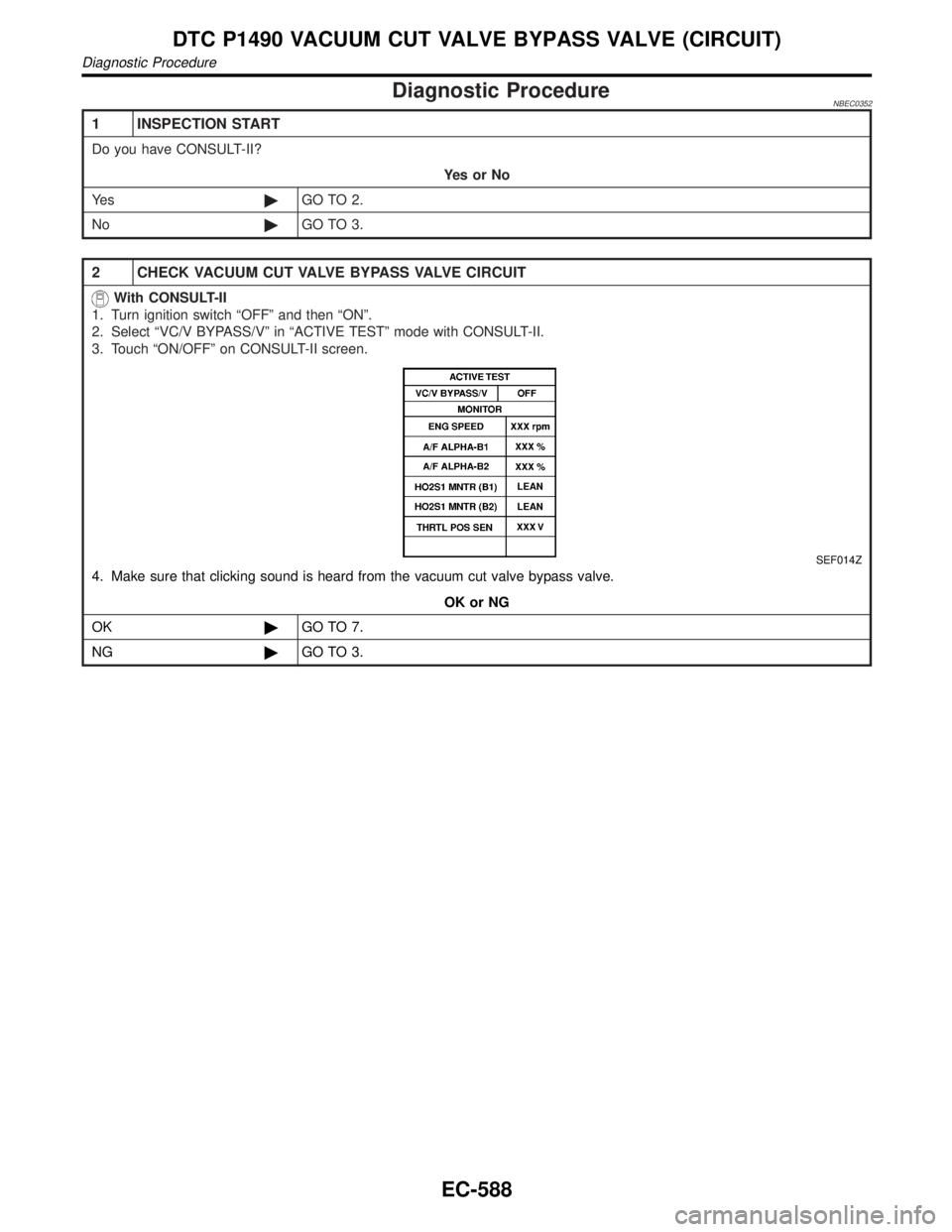
2 CHECK VACUUM CUT VALVE BYPASS VALVE CIRCUIT
With CONSULT-II
1. Turn ignition switch ªOFFº and then ªONº.
2. Select ªVC/V BYPASS/Vº in ªACTIVE TESTº mode with CONSULT-II.
3. Touch ªON/OFFº on CONSULT-II screen.
SEF014Z
4. Make sure that clicking sound is heard from the vacuum cut valve bypass valve.
OK or NG
OK©GO TO 7.
NG©GO TO 3.
DTC P1490 VACUUM CUT VALVE BYPASS VALVE (CIRCUIT)
Diagnostic Procedure
EC-588
Page 1127 of 2395

On Board Diagnosis LogicNBEC0356Malfunction is detected when vacuum cut valve bypass valve does
not operate properly.
Possible CauseNBEC0593IVacuum cut valve bypass valve
IVacuum cut valve
IBypass hoses for clogging
IEVAP control system pressure sensor and circuit
IEVAP canister vent control valve
IHose between fuel tank and vacuum cut valve clogged
IHose between vacuum cut valve and EVAP canister clogged
IEVAP canister
IEVAP purge port of fuel tank for clogging
SEF210Y
SEF211Y
SEF239Y
DTC Confirmation ProcedureNBEC0357CAUTION:
Always drive vehicle at a safe speed.
NOTE:
If ªDTC Confirmation Procedureº has been previously conducted,
always turn ignition switch ªOFFº and wait at least 10 seconds
before conducting the next test.
TESTING CONDITION:
For best results, perform test at a temperature of 5 to 30ÉC (41
to 86ÉF).
WITH CONSULT-IINBEC0357S011) Turn ignition switch ªONº.
2) Start engine and warm it up to normal operating temperature.
3) Turn ignition switch ªOFFº and wait at least 10 seconds.
4) Start engine and let it idle for at least 70 seconds.
5) Select ªVC CUT/V BP/V P1491º of ªEVAPORATIVE SYSTEMº
in ªDTC WORK SUPPORTº mode with CONSULT-II.
6) Touch ªSTARTº.
7) When the following conditions are met, ªTESTINGº will be dis-
played on the CONSULT-II screen. Maintain the conditions
continuously until ªTESTINGº changes to ªCOMPLETEDº. (It
will take at least 30 seconds.)
ENG SPEED Idle speed or more
Selector lever Suitable position
Vehicle speed 37 km/h (23 MPH) or more
B/FUEL SCHDL 1.3 - 10 msec
If ªTESTINGº is not displayed after 5 minutes, retry from
step 3.
8) Make sure that ªOKº is displayed after touching ªSELF-DIAG
DTC P1491 VACUUM CUT VALVE BYPASS VALVE
On Board Diagnosis Logic
EC-592