audio INFINITI QX4 2001 Factory Owner's Manual
[x] Cancel search | Manufacturer: INFINITI, Model Year: 2001, Model line: QX4, Model: INFINITI QX4 2001Pages: 2395, PDF Size: 43.2 MB
Page 1642 of 2395

NBEL0145
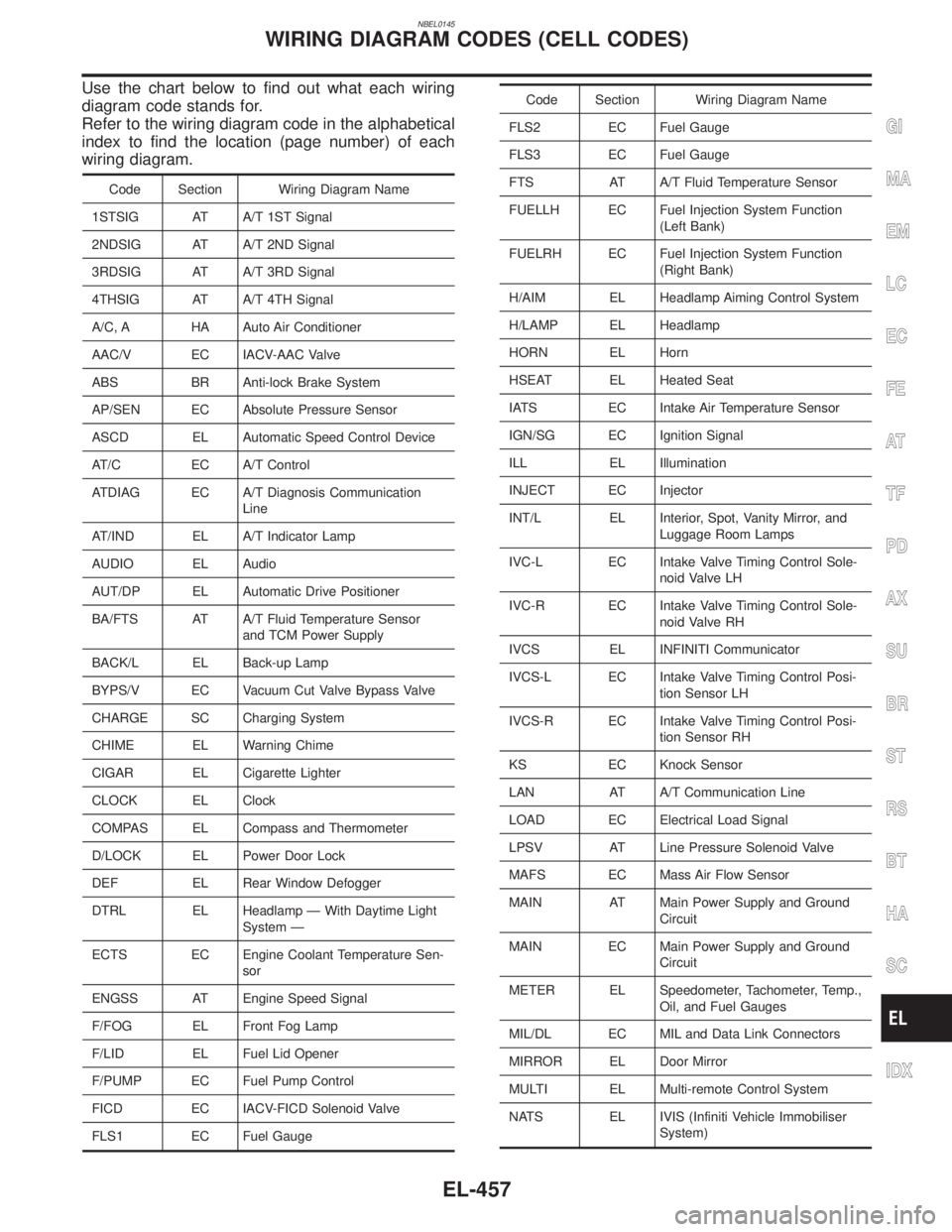
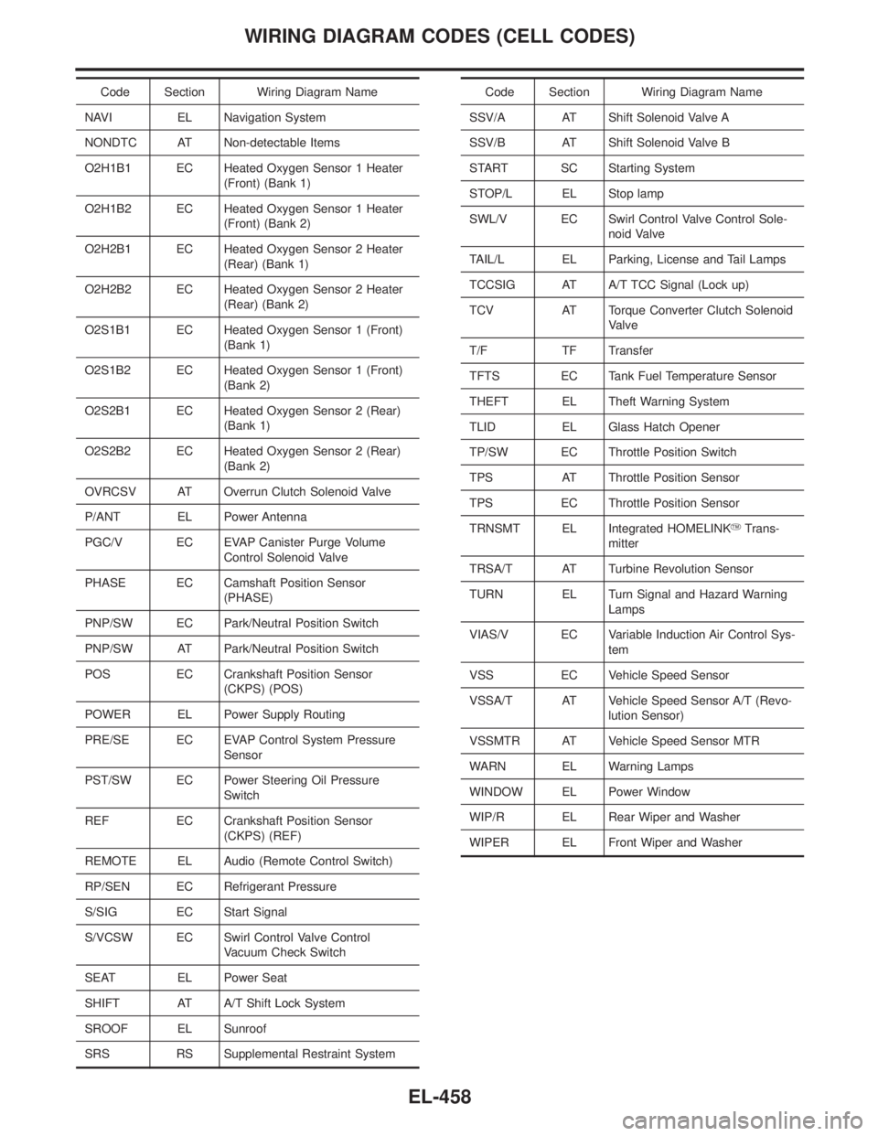
Use the chart below to find out what each wiring
diagram code stands for.
Refer to the wiring diagram code in the alphabetical
index to find the location (page number) of each
wiring diagram.
Code Section Wiring Diagram Name
1STSIG AT A/T 1ST Signal
2NDSIG AT A/T 2ND Signal
3RDSIG AT A/T 3RD Signal
4THSIG AT A/T 4TH Signal
A/C, A HA Auto Air Conditioner
AAC/V EC IACV-AAC Valve
ABS BR Anti-lock Brake System
AP/SEN EC Absolute Pressure Sensor
ASCD EL Automatic Speed Control Device
AT/C EC A/T Control
ATDIAG EC A/T Diagnosis Communication
Line
AT/IND EL A/T Indicator Lamp
AUDIO EL Audio
AUT/DP EL Automatic Drive Positioner
BA/FTS AT A/T Fluid Temperature Sensor
and TCM Power Supply
BACK/L EL Back-up Lamp
BYPS/V EC Vacuum Cut Valve Bypass Valve
CHARGE SC Charging System
CHIME EL Warning Chime
CIGAR EL Cigarette Lighter
CLOCK EL Clock
COMPAS EL Compass and Thermometer
D/LOCK EL Power Door Lock
DEF EL Rear Window Defogger
DTRL EL Headlamp Ð With Daytime Light
System Ð
ECTS EC Engine Coolant Temperature Sen-
sor
ENGSS AT Engine Speed Signal
F/FOG EL Front Fog Lamp
F/LID EL Fuel Lid Opener
F/PUMP EC Fuel Pump Control
FICD EC IACV-FICD Solenoid Valve
FLS1 EC Fuel Gauge
Code Section Wiring Diagram Name
FLS2 EC Fuel Gauge
FLS3 EC Fuel Gauge
FTS AT A/T Fluid Temperature Sensor
FUELLH EC Fuel Injection System Function
(Left Bank)
FUELRH EC Fuel Injection System Function
(Right Bank)
H/AIM EL Headlamp Aiming Control System
H/LAMP EL Headlamp
HORN EL Horn
HSEAT EL Heated Seat
IATS EC Intake Air Temperature Sensor
IGN/SG EC Ignition Signal
ILL EL Illumination
INJECT EC Injector
INT/L EL Interior, Spot, Vanity Mirror, and
Luggage Room Lamps
IVC-L EC Intake Valve Timing Control Sole-
noid Valve LH
IVC-R EC Intake Valve Timing Control Sole-
noid Valve RH
IVCS EL INFINITI Communicator
IVCS-L EC Intake Valve Timing Control Posi-
tion Sensor LH
IVCS-R EC Intake Valve Timing Control Posi-
tion Sensor RH
KS EC Knock Sensor
LAN AT A/T Communication Line
LOAD EC Electrical Load Signal
LPSV AT Line Pressure Solenoid Valve
MAFS EC Mass Air Flow Sensor
MAIN AT Main Power Supply and Ground
Circuit
MAIN EC Main Power Supply and Ground
Circuit
METER EL Speedometer, Tachometer, Temp.,
Oil, and Fuel Gauges
MIL/DL EC MIL and Data Link Connectors
MIRROR EL Door Mirror
MULTI EL Multi-remote Control System
NATS EL IVIS (Infiniti Vehicle Immobiliser
System)
GI
MA
EM
LC
EC
FE
AT
TF
PD
AX
SU
BR
ST
RS
BT
HA
SC
IDX
WIRING DIAGRAM CODES (CELL CODES)
EL-457
Page 1643 of 2395

Code Section Wiring Diagram Name
NAVI EL Navigation System
NONDTC AT Non-detectable Items
O2H1B1 EC Heated Oxygen Sensor 1 Heater
(Front) (Bank 1)
O2H1B2 EC Heated Oxygen Sensor 1 Heater
(Front) (Bank 2)
O2H2B1 EC Heated Oxygen Sensor 2 Heater
(Rear) (Bank 1)
O2H2B2 EC Heated Oxygen Sensor 2 Heater
(Rear) (Bank 2)
O2S1B1 EC Heated Oxygen Sensor 1 (Front)
(Bank 1)
O2S1B2 EC Heated Oxygen Sensor 1 (Front)
(Bank 2)
O2S2B1 EC Heated Oxygen Sensor 2 (Rear)
(Bank 1)
O2S2B2 EC Heated Oxygen Sensor 2 (Rear)
(Bank 2)
OVRCSV AT Overrun Clutch Solenoid Valve
P/ANT EL Power Antenna
PGC/V EC EVAP Canister Purge Volume
Control Solenoid Valve
PHASE EC Camshaft Position Sensor
(PHASE)
PNP/SW EC Park/Neutral Position Switch
PNP/SW AT Park/Neutral Position Switch
POS EC Crankshaft Position Sensor
(CKPS) (POS)
POWER EL Power Supply Routing
PRE/SE EC EVAP Control System Pressure
Sensor
PST/SW EC Power Steering Oil Pressure
Switch
REF EC Crankshaft Position Sensor
(CKPS) (REF)
REMOTE EL Audio (Remote Control Switch)
RP/SEN EC Refrigerant Pressure
S/SIG EC Start Signal
S/VCSW EC Swirl Control Valve Control
Vacuum Check Switch
SEAT EL Power Seat
SHIFT AT A/T Shift Lock System
SROOF EL Sunroof
SRS RS Supplemental Restraint SystemCode Section Wiring Diagram Name
SSV/A AT Shift Solenoid Valve A
SSV/B AT Shift Solenoid Valve B
START SC Starting System
STOP/L EL Stop lamp
SWL/V EC Swirl Control Valve Control Sole-
noid Valve
TAIL/L EL Parking, License and Tail Lamps
TCCSIG AT A/T TCC Signal (Lock up)
TCV AT Torque Converter Clutch Solenoid
Valve
T/F TF Transfer
TFTS EC Tank Fuel Temperature Sensor
THEFT EL Theft Warning System
TLID EL Glass Hatch Opener
TP/SW EC Throttle Position Switch
TPS AT Throttle Position Sensor
TPS EC Throttle Position Sensor
TRNSMT EL Integrated HOMELINKYTrans-
mitter
TRSA/T AT Turbine Revolution Sensor
TURN EL Turn Signal and Hazard Warning
Lamps
VIAS/V EC Variable Induction Air Control Sys-
tem
VSS EC Vehicle Speed Sensor
VSSA/T AT Vehicle Speed Sensor A/T (Revo-
lution Sensor)
VSSMTR AT Vehicle Speed Sensor MTR
WARN EL Warning Lamps
WINDOW EL Power Window
WIP/R EL Rear Wiper and Washer
WIPER EL Front Wiper and Washer
WIRING DIAGRAM CODES (CELL CODES)
EL-458
Page 1869 of 2395

RHA463GA
RHA334HA
8. Check AUTO ModeNBHA0019S02081. Press AUTO switch.
2. Display should indicate AUTO (no ECON).
Confirm that the compressor clutch engages (audio or visual
inspection).
(Discharge air and blower speed will depend on ambient, in-
vehicle and set temperatures.)
If NG, go to trouble diagnosis procedure for A/C system (HA-71),
then if necessary, trouble diagnosis procedure for magnet clutch
(HA-104).
SHA286HA
9. Check Ambient Display (With Navigation System)NBHA0019S02091. Press AUTO switch.
2. Press AMB switch.
3. Display should show the outside (ambient) temperature for
approximately 5 seconds.
If NG, go to trouble diagnosis procedure for multiplex communica-
tion circuit (HA-142).
If all operational check are OK (symptom can not be duplicated),
go to ªIncident Simulation Testsº (GI section) and perform tests as
outlined to simulate driving conditions environment. If symptom
appears, refer to ªSymptom Tableº (HA-65) and perform applicable
trouble diagnosis procedures.
TROUBLE DIAGNOSES
Operational Check (Cont'd)
HA-70
Page 1961 of 2395

A
AAC/V - Wiring diagram ...............................EC-425
ABS - Wiring diagram ....................................BR-37
ABS sensor rotor ........................................AX-6, 19
Absolute pressure sensor ............................EC-158
A/C air flow .....................................................HA-25
A/C component layout ....................................HA-19
A/C compressor clutch removal and
installation .................................................HA-150
A/C compressor precaution..............................HA-6
A/C compressor special service tool..............HA-10
A/C control operation (auto A/C) ....................HA-23
A/C diagnostic work flow (auto A/C) ..............HA-65
A/C HFC134a (R134a) system
precaution .....................................................HA-2
A/C HFC134a (R134a) system service
procedure ..................................................HA-144
A/C HFC134a (R134a) system service
tools.............................................................HA-11
A/C HFC134a system service equip-
ment precaution ............................................HA-7
A/C lubricant (R134a)...................................HA-146
A/C operational check ....................................HA-66
A/C performance chart .................................HA-116
A/C performance test diagnoses ..................HA-114
A/C relay .......................................................HA-110
A/C self-diagnoses (auto A/C)........................HA-44
A/C service data specification ......................HA-160
A/C system description (auto A/C) .................HA-23
A/C trouble diagnoses (auto A/C) ..................HA-27
A/C, A - Wiring diagram ...........................HA-31, 36
Accelerator control system ...............................FE-3
Accelerator wire adjustment .............................FE-3
Actuator lever (Transfer) ...............................TF-120
Air bag ............................................................RS-10
Air bag disposal..............................................RS-22
Air bag precautions ...........................................GI-3
Air bleeding for brake system ..........................BR-8
Air cleaner filter replacement .........................MA-17
Air conditioner cut control ..............................EC-31
Air flow meter - See Mass air flow
sensor .......................................................EC-150
Air mix door control linkage adjustment.........HA-85
Air mix. door motor ................................HA-82, 141
Air spoiler, rear................................................BT-35
All - mode 4WD system ..................................TF-10
Alternator ........................................................SC-28
Ambient sensor ............................................HA-129
Angular tightening application..........................EM-3
Antenna - See Power antenna .....................EL-169
Anti-lock brake system - Wiring
diagram .......................................................BR-37
AP/SEN - Wiring diagram ............................EC-160
ASCD (automatic speed control device) ......EL-221
ASCD - Wiring diagram ................................EL-225
A/T - Wiring diagram - AT - FTS ...................AT-107
A/T - Wiring diagram - AT - MAIN ...................AT-96
A/T - Wiring diagram - AT - PNP/SW............AT-101A/T - Wiring diagram - AT - VSS A/T ............AT-113
A/T control ....................................................EC-440
A/T diagnosis communication line................EC-603
A/T fluid temperature sensor .........................AT-110
A/T self-diagnoses...........................................AT-46
A/T shift lock system .....................................AT-265
A/T shift lock system - Wiring diagram .........AT-266
A/T trouble diagnoses .....................................AT-53
A/T Wiring diagram - AT - ENG SS...............AT-117
A/T Wiring diagram AT - 1ST ........................AT-123
A/T Wiring diagram AT - 2ND .......................AT-129
A/T Wiring diagram AT - 3RD .......................AT-135
A/T Wiring diagram AT - 4TH ........................AT-142
A/T Wiring diagram AT - BA/FTS ..................AT-192
A/T Wiring diagram AT - LPSV .....................AT-164
A/T Wiring diagram AT - NONDTC ...............AT-215
A/T Wiring diagram AT - OVRCSV ...............AT-187
A/T Wiring diagram AT - SSV/A ....................AT-169
A/T Wiring diagram AT - SSV/B ....................AT-173
A/T Wiring diagram AT - TCCSIG .................AT-156
A/T Wiring diagram AT - TCV .......................AT-150
A/T Wiring diagram AT - TPS........................AT-179
A/T Wiring diagram AT - VSSMTR................AT-199
AT/C - Wiring diagram ..................................EC-442
ATP switch.....................................................TF-112
ATP warning lamp .........................................TF-102
Audio .............................................................EL-160
AUDIO - Wiring diagram ...............................EL-162
Audio and A/C control removal and
installation - See Instrument panel .............BT-21
AUT/DP - Wiring diagram .............................EL-191
Auto air conditioner - Wiring diagram ......HA-31, 36
Automatic amplifier...................................HA-40, 72
Automatic drive positioner ............................EL-186
Automatic speed control system - See
ASCD ........................................................EL-221
Automatic transmission fluid
replacement ................................................MA-21
Automatic transmission number ......................GI-43
Auxiliary air control (AAC) valve ..................EC-422
Axle housing (rear) .........................................AX-19
B
Back door ........................................................BT-15
Back door opener - See Back door ................BT-15
Back door trim.................................................BT-34
Back-up lamp ..................................................EL-69
BACK/L - Wiring diagram................................EL-69
Ball joint (front) ...............................................SU-12
Base idle air volume initialiging......................EC-57
Basic inspection ...........................................EC-101
Battery ..............................................................SC-4
Battery/Starting/Charging System
Tester ................................................SC-7, 12, 21
Blower motor ..................................................HA-95
Body alignment ...............................................BT-57
Brake booster .................................................BR-19
Brake control valve (Proportioning
valve)...........................................................BR-11
ALPHABETICAL INDEX
IDX-2
Page 1966 of 2395

Propeller shaft greasing .................................MA-23
Propeller shaft inspection ..............................MA-23
Propeller shaft on vehicle service ....................PD-6
Propeller shaft vibration ...................................PD-6
PST/SW - Wiring diagram ............................EC-635
R
Rack retainer adjustment ..................................ST-8
Radiator ....................................................LC-19, 21
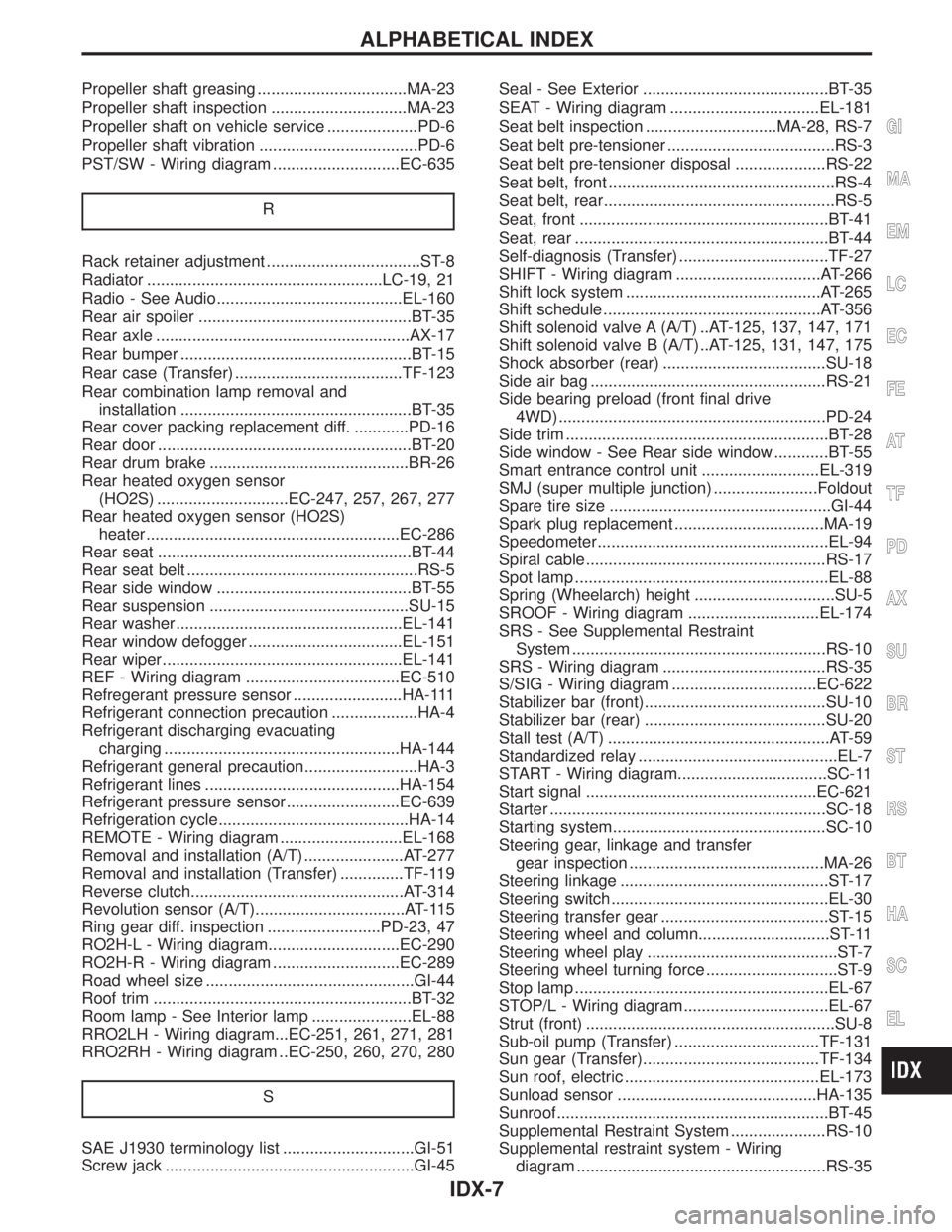
Radio - See Audio.........................................EL-160
Rear air spoiler ...............................................BT-35
Rear axle ........................................................AX-17
Rear bumper ...................................................BT-15
Rear case (Transfer) .....................................TF-123
Rear combination lamp removal and
installation ...................................................BT-35
Rear cover packing replacement diff. ............PD-16
Rear door ........................................................BT-20
Rear drum brake ............................................BR-26
Rear heated oxygen sensor
(HO2S) .............................EC-247, 257, 267, 277
Rear heated oxygen sensor (HO2S)
heater ........................................................EC-286
Rear seat ........................................................BT-44
Rear seat belt ...................................................RS-5
Rear side window ...........................................BT-55
Rear suspension ............................................SU-15
Rear washer..................................................EL-141
Rear window defogger ..................................EL-151
Rear wiper.....................................................EL-141
REF - Wiring diagram ..................................EC-510
Refregerant pressure sensor ........................HA-111
Refrigerant connection precaution ...................HA-4
Refrigerant discharging evacuating
charging ....................................................HA-144
Refrigerant general precaution.........................HA-3
Refrigerant lines ...........................................HA-154
Refrigerant pressure sensor.........................EC-639
Refrigeration cycle..........................................HA-14
REMOTE - Wiring diagram ...........................EL-168
Removal and installation (A/T) ......................AT-277
Removal and installation (Transfer) ..............TF-119
Reverse clutch...............................................AT-314
Revolution sensor (A/T).................................AT-115
Ring gear diff. inspection .........................PD-23, 47
RO2H-L - Wiring diagram.............................EC-290
RO2H-R - Wiring diagram ............................EC-289
Road wheel size ..............................................GI-44
Roof trim .........................................................BT-32
Room lamp - See Interior lamp ......................EL-88
RRO2LH - Wiring diagram...EC-251, 261, 271, 281
RRO2RH - Wiring diagram ..EC-250, 260, 270, 280
S
SAE J1930 terminology list .............................GI-51
Screw jack .......................................................GI-45Seal - See Exterior .........................................BT-35
SEAT - Wiring diagram .................................EL-181
Seat belt inspection .............................MA-28, RS-7
Seat belt pre-tensioner .....................................RS-3
Seat belt pre-tensioner disposal ....................RS-22
Seat belt, front ..................................................RS-4
Seat belt, rear...................................................RS-5
Seat, front .......................................................BT-41
Seat, rear ........................................................BT-44
Self-diagnosis (Transfer) .................................TF-27
SHIFT - Wiring diagram ................................AT-266
Shift lock system ...........................................AT-265
Shift schedule ................................................AT-356
Shift solenoid valve A (A/T) ..AT-125, 137, 147, 171
Shift solenoid valve B (A/T) ..AT-125, 131, 147, 175
Shock absorber (rear) ....................................SU-18
Side air bag ....................................................RS-21
Side bearing preload (front final drive
4WD) ...........................................................PD-24
Side trim ..........................................................BT-28
Side window - See Rear side window ............BT-55
Smart entrance control unit ..........................EL-319
SMJ (super multiple junction) .......................Foldout
Spare tire size .................................................GI-44
Spark plug replacement .................................MA-19
Speedometer...................................................EL-94
Spiral cable.....................................................RS-17
Spot lamp ........................................................EL-88
Spring (Wheelarch) height ...............................SU-5
SROOF - Wiring diagram .............................EL-174
SRS - See Supplemental Restraint
System ........................................................RS-10
SRS - Wiring diagram ....................................RS-35
S/SIG - Wiring diagram ................................EC-622
Stabilizer bar (front)........................................SU-10
Stabilizer bar (rear) ........................................SU-20
Stall test (A/T) .................................................AT-59
Standardized relay ............................................EL-7
START - Wiring diagram.................................SC-11
Start signal ...................................................EC-621
Starter .............................................................SC-18
Starting system...............................................SC-10
Steering gear, linkage and transfer
gear inspection ...........................................MA-26
Steering linkage ..............................................ST-17
Steering switch................................................EL-30
Steering transfer gear .....................................ST-15
Steering wheel and column.............................ST-11
Steering wheel play ..........................................ST-7
Steering wheel turning force .............................ST-9
Stop lamp ........................................................EL-67
STOP/L - Wiring diagram................................EL-67
Strut (front) .......................................................SU-8
Sub-oil pump (Transfer) ................................TF-131
Sun gear (Transfer).......................................TF-134
Sun roof, electric ...........................................EL-173
Sunload sensor ............................................HA-135
Sunroof............................................................BT-45
Supplemental Restraint System .....................RS-10
Supplemental restraint system - Wiring
diagram .......................................................RS-35
GI
MA
EM
LC
EC
FE
AT
TF
PD
AX
SU
BR
ST
RS
BT
HA
SC
EL
ALPHABETICAL INDEX
IDX-7
Page 2106 of 2395

Driver Air Bag Module and Spiral Cable
REMOVAL AND INSTALLATIONNBRS0013
SRS782-A
SBF811E
REMOVALNBRS0014CAUTION:
IBefore servicing SRS, turn the ignition switch off, discon-
nect both battery cables and wait at least 3 minutes.
IAlways work from the side of air bag module.
1. Remove lower lid from steering wheel, and disconnect air bag
module connector.
SBF812E
2. Remove side lids, ASCD steering switch and Audio steering
switch (or TEL switch). Using the TAMPER RESISTANT TORX
(Size T50), remove left and right special bolts. Air bag module
can then be removed.
SRS161
CAUTION:
IAlways place air bag module with pad side facing upward.
IDo not attempt to disassemble air bag module.
IThe special bolts are coated with bonding agent. Do not
use old bolts after removal; replace with new ones.
IDo not insert any foreign objects (screwdriver, etc.) into
air bag module connector.
GI
MA
EM
LC
EC
FE
AT
TF
PD
AX
SU
BR
ST
BT
HA
SC
EL
IDX
SUPPLEMENTAL RESTRAINT SYSTEM (SRS)
Driver Air Bag Module and Spiral Cable
RS-17
Page 2289 of 2395

SMT862D
Transfer Control Unit Terminals and Reference
Value
NBTF0018REMOVAL AND INSTALLATION OF TRANSFER
CONTROL UNIT
NBTF0018S03RemovalNBTF0018S03011. Turn ignition switch OFF and disconnect negative battery ter-
minal.
2. Remove console box.
3. Remove cluster lid C.
4. Remove audio assembly and A/C control unit.
5. Remove instrument lower panel on driver side.
6. Remove glove box.
7. Remove instrument lower panel on passenger side.
8. Remove instrument lower center panel.
9. Remove transfer control unit.
IFor steps 2 through 8 above, refer to BT-21, ªInstrument Panel
Assemblyº.
InstallationNBTF0018S0302IInstallation is in the reverse order of removal.
When installing transfer control unit, tighten transfer control unit
lock nut.
Tightening torque:
: 4.3 - 5.8 N´m (0.44 - 0.59 kg-m, 38 - 51 in-lb)
SMT771D
INSPECTION OF TRANSFER CONTROL UNITNBTF0018S01IMeasure voltage between each terminal and terminal 6 or 45
by following ªTRANSFER CONTROL UNIT INSPECTION
TABLEº, TF-55.
IPin connector terminal layout
TROUBLE DIAGNOSIS Ð GENERAL DESCRIPTION
Transfer Control Unit Terminals and Reference Value
TF-54