diagram INFINITI QX4 2001 Factory Service Manual
[x] Cancel search | Manufacturer: INFINITI, Model Year: 2001, Model line: QX4, Model: INFINITI QX4 2001Pages: 2395, PDF Size: 43.2 MB
Page 1966 of 2395
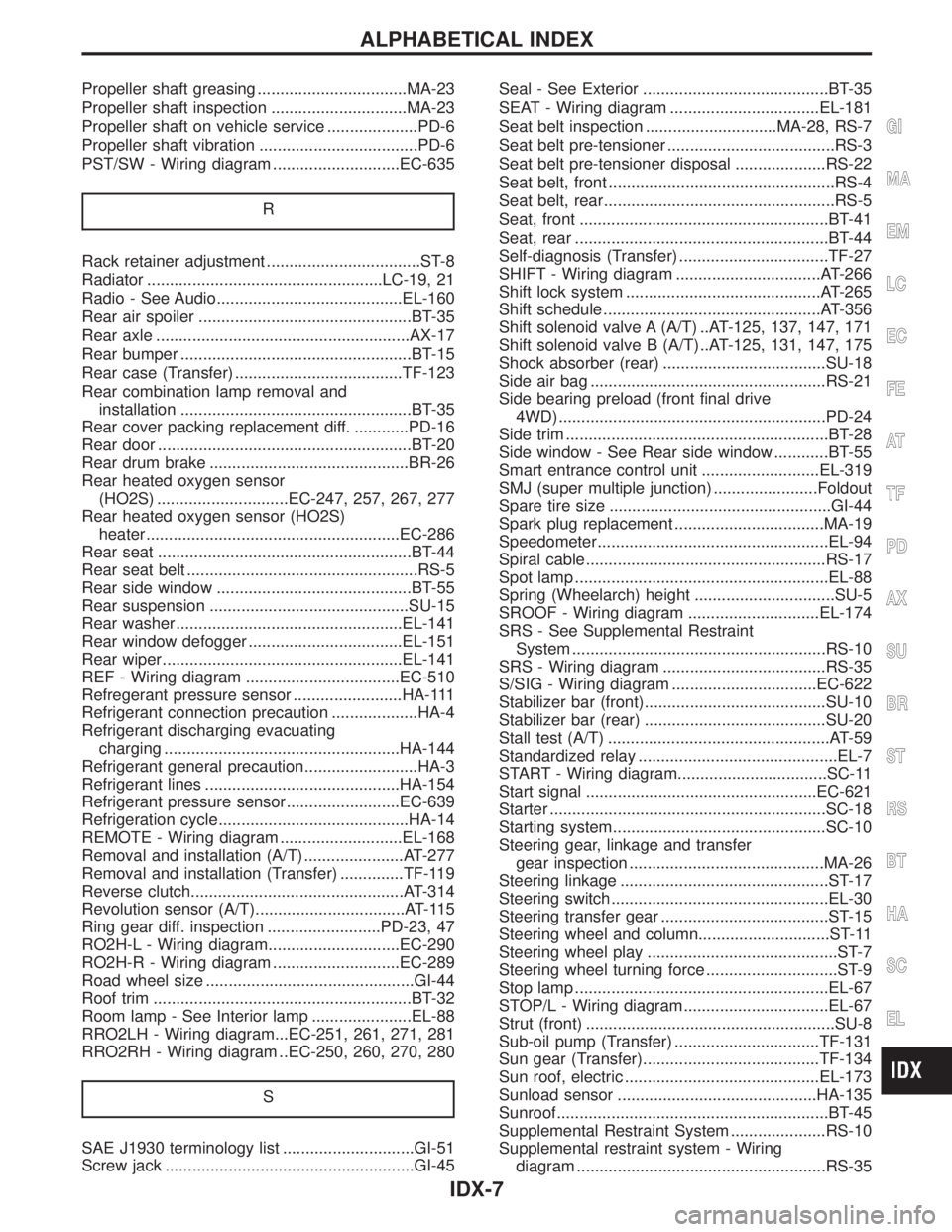
Propeller shaft greasing .................................MA-23
Propeller shaft inspection ..............................MA-23
Propeller shaft on vehicle service ....................PD-6
Propeller shaft vibration ...................................PD-6
PST/SW - Wiring diagram ............................EC-635
R
Rack retainer adjustment ..................................ST-8
Radiator ....................................................LC-19, 21
Radio - See Audio.........................................EL-160
Rear air spoiler ...............................................BT-35
Rear axle ........................................................AX-17
Rear bumper ...................................................BT-15
Rear case (Transfer) .....................................TF-123
Rear combination lamp removal and
installation ...................................................BT-35
Rear cover packing replacement diff. ............PD-16
Rear door ........................................................BT-20
Rear drum brake ............................................BR-26
Rear heated oxygen sensor
(HO2S) .............................EC-247, 257, 267, 277
Rear heated oxygen sensor (HO2S)
heater ........................................................EC-286
Rear seat ........................................................BT-44
Rear seat belt ...................................................RS-5
Rear side window ...........................................BT-55
Rear suspension ............................................SU-15
Rear washer..................................................EL-141
Rear window defogger ..................................EL-151
Rear wiper.....................................................EL-141
REF - Wiring diagram ..................................EC-510
Refregerant pressure sensor ........................HA-111
Refrigerant connection precaution ...................HA-4
Refrigerant discharging evacuating
charging ....................................................HA-144
Refrigerant general precaution.........................HA-3
Refrigerant lines ...........................................HA-154
Refrigerant pressure sensor.........................EC-639
Refrigeration cycle..........................................HA-14
REMOTE - Wiring diagram ...........................EL-168
Removal and installation (A/T) ......................AT-277
Removal and installation (Transfer) ..............TF-119
Reverse clutch...............................................AT-314
Revolution sensor (A/T).................................AT-115
Ring gear diff. inspection .........................PD-23, 47
RO2H-L - Wiring diagram.............................EC-290
RO2H-R - Wiring diagram ............................EC-289
Road wheel size ..............................................GI-44
Roof trim .........................................................BT-32
Room lamp - See Interior lamp ......................EL-88
RRO2LH - Wiring diagram...EC-251, 261, 271, 281
RRO2RH - Wiring diagram ..EC-250, 260, 270, 280
S
SAE J1930 terminology list .............................GI-51
Screw jack .......................................................GI-45Seal - See Exterior .........................................BT-35
SEAT - Wiring diagram .................................EL-181
Seat belt inspection .............................MA-28, RS-7
Seat belt pre-tensioner .....................................RS-3
Seat belt pre-tensioner disposal ....................RS-22
Seat belt, front ..................................................RS-4
Seat belt, rear...................................................RS-5
Seat, front .......................................................BT-41
Seat, rear ........................................................BT-44
Self-diagnosis (Transfer) .................................TF-27
SHIFT - Wiring diagram ................................AT-266
Shift lock system ...........................................AT-265
Shift schedule ................................................AT-356
Shift solenoid valve A (A/T) ..AT-125, 137, 147, 171
Shift solenoid valve B (A/T) ..AT-125, 131, 147, 175
Shock absorber (rear) ....................................SU-18
Side air bag ....................................................RS-21
Side bearing preload (front final drive
4WD) ...........................................................PD-24
Side trim ..........................................................BT-28
Side window - See Rear side window ............BT-55
Smart entrance control unit ..........................EL-319
SMJ (super multiple junction) .......................Foldout
Spare tire size .................................................GI-44
Spark plug replacement .................................MA-19
Speedometer...................................................EL-94
Spiral cable.....................................................RS-17
Spot lamp ........................................................EL-88
Spring (Wheelarch) height ...............................SU-5
SROOF - Wiring diagram .............................EL-174
SRS - See Supplemental Restraint
System ........................................................RS-10
SRS - Wiring diagram ....................................RS-35
S/SIG - Wiring diagram ................................EC-622
Stabilizer bar (front)........................................SU-10
Stabilizer bar (rear) ........................................SU-20
Stall test (A/T) .................................................AT-59
Standardized relay ............................................EL-7
START - Wiring diagram.................................SC-11
Start signal ...................................................EC-621
Starter .............................................................SC-18
Starting system...............................................SC-10
Steering gear, linkage and transfer
gear inspection ...........................................MA-26
Steering linkage ..............................................ST-17
Steering switch................................................EL-30
Steering transfer gear .....................................ST-15
Steering wheel and column.............................ST-11
Steering wheel play ..........................................ST-7
Steering wheel turning force .............................ST-9
Stop lamp ........................................................EL-67
STOP/L - Wiring diagram................................EL-67
Strut (front) .......................................................SU-8
Sub-oil pump (Transfer) ................................TF-131
Sun gear (Transfer).......................................TF-134
Sun roof, electric ...........................................EL-173
Sunload sensor ............................................HA-135
Sunroof............................................................BT-45
Supplemental Restraint System .....................RS-10
Supplemental restraint system - Wiring
diagram .......................................................RS-35
GI
MA
EM
LC
EC
FE
AT
TF
PD
AX
SU
BR
ST
RS
BT
HA
SC
EL
ALPHABETICAL INDEX
IDX-7
Page 1967 of 2395
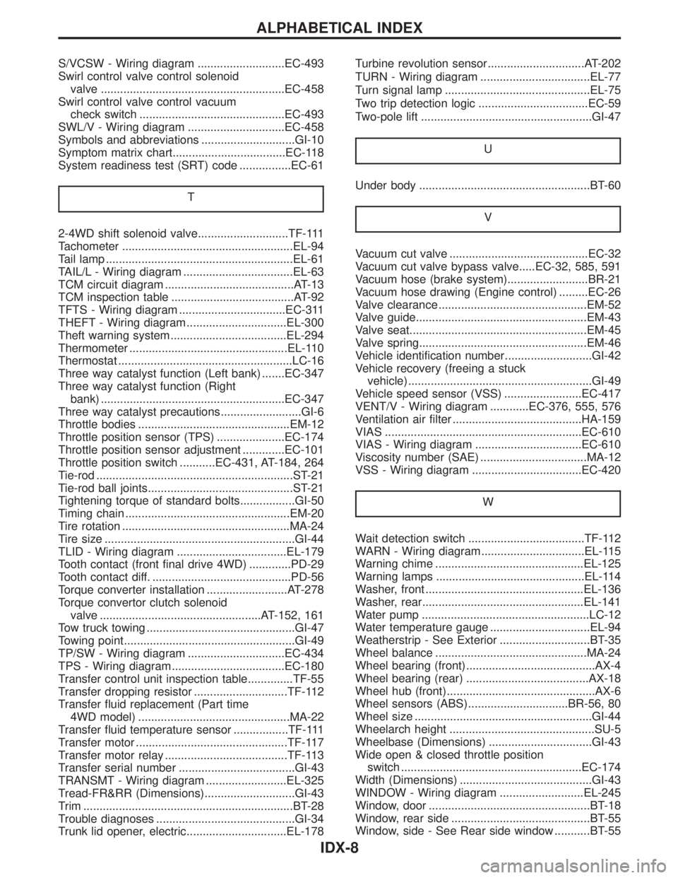
S/VCSW - Wiring diagram ...........................EC-493
Swirl control valve control solenoid
valve .........................................................EC-458
Swirl control valve control vacuum
check switch .............................................EC-493
SWL/V - Wiring diagram ..............................EC-458
Symbols and abbreviations .............................GI-10
Symptom matrix chart...................................EC-118
System readiness test (SRT) code ................EC-61
T
2-4WD shift solenoid valve............................TF-111
Tachometer .....................................................EL-94
Tail lamp ..........................................................EL-61
TAIL/L - Wiring diagram ..................................EL-63
TCM circuit diagram ........................................AT-13
TCM inspection table ......................................AT-92
TFTS - Wiring diagram .................................EC-311
THEFT - Wiring diagram ...............................EL-300
Theft warning system....................................EL-294
Thermometer .................................................EL-110
Thermostat ......................................................LC-16
Three way catalyst function (Left bank) .......EC-347
Three way catalyst function (Right
bank) .........................................................EC-347
Three way catalyst precautions.........................GI-6
Throttle bodies ...............................................EM-12
Throttle position sensor (TPS) .....................EC-174
Throttle position sensor adjustment .............EC-101
Throttle position switch ...........EC-431, AT-184, 264
Tie-rod .............................................................ST-21
Tie-rod ball joints.............................................ST-21
Tightening torque of standard bolts.................GI-50
Timing chain ...................................................EM-20
Tire rotation ....................................................MA-24
Tire size ...........................................................GI-44
TLID - Wiring diagram ..................................EL-179
Tooth contact (front final drive 4WD) .............PD-29
Tooth contact diff. ...........................................PD-56
Torque converter installation .........................AT-278
Torque convertor clutch solenoid
valve ..................................................AT-152, 161
Tow truck towing ..............................................GI-47
Towing point.....................................................GI-49
TP/SW - Wiring diagram ..............................EC-434
TPS - Wiring diagram...................................EC-180
Transfer control unit inspection table..............TF-55
Transfer dropping resistor .............................TF-112
Transfer fluid replacement (Part time
4WD model) ...............................................MA-22
Transfer fluid temperature sensor .................TF-111
Transfer motor ...............................................TF-117
Transfer motor relay ......................................TF-113
Transfer serial number ....................................GI-43
TRANSMT - Wiring diagram .........................EL-325
Tread-FR&RR (Dimensions)............................GI-43
Trim .................................................................BT-28
Trouble diagnoses ...........................................GI-34
Trunk lid opener, electric...............................EL-178Turbine revolution sensor..............................AT-202
TURN - Wiring diagram ..................................EL-77
Turn signal lamp .............................................EL-75
Two trip detection logic ..................................EC-59
Two-pole lift .....................................................GI-47
U
Under body .....................................................BT-60
V
Vacuum cut valve ...........................................EC-32
Vacuum cut valve bypass valve.....EC-32, 585, 591
Vacuum hose (brake system).........................BR-21
Vacuum hose drawing (Engine control) .........EC-26
Valve clearance ..............................................EM-52
Valve guide.....................................................EM-43
Valve seat.......................................................EM-45
Valve spring....................................................EM-46
Vehicle identification number...........................GI-42
Vehicle recovery (freeing a stuck
vehicle) .........................................................GI-49
Vehicle speed sensor (VSS) ........................EC-417
VENT/V - Wiring diagram ............EC-376, 555, 576
Ventilation air filter ........................................HA-159
VIAS .............................................................EC-610
VIAS - Wiring diagram .................................EC-610
Viscosity number (SAE) .................................MA-12
VSS - Wiring diagram ..................................EC-420
W
Wait detection switch ....................................TF-112
WARN - Wiring diagram................................EL-115
Warning chime ..............................................EL-125
Warning lamps ..............................................EL-114
Washer, front .................................................EL-136
Washer, rear..................................................EL-141
Water pump ....................................................LC-12
Water temperature gauge ...............................EL-94
Weatherstrip - See Exterior ............................BT-35
Wheel balance ...............................................MA-24
Wheel bearing (front)........................................AX-4
Wheel bearing (rear) ......................................AX-18
Wheel hub (front)..............................................AX-6
Wheel sensors (ABS)...............................BR-56, 80
Wheel size .......................................................GI-44
Wheelarch height .............................................SU-5
Wheelbase (Dimensions) ................................GI-43
Wide open & closed throttle position
switch ........................................................EC-174
Width (Dimensions) .........................................GI-43
WINDOW - Wiring diagram ..........................EL-245
Window, door ..................................................BT-18
Window, rear side ...........................................BT-55
Window, side - See Rear side window ...........BT-55
ALPHABETICAL INDEX
IDX-8
Page 1968 of 2395

Windshield.......................................................BT-53
WIP/R - Wiring diagram ................................EL-143
WIPER - Wiring diagram ..............................EL-138
Wiper, front....................................................EL-136
Wiper, rear ....................................................EL-141Wiring Diagram (Cell code) list .....................EL-457
Wiring diagram (Transfer) ...............................TF-18
Wiring diagrams ...............................................GI-11
Wrist pin - See Piston pin inspection.............EM-63
GI
MA
EM
LC
EC
FE
AT
TF
PD
AX
SU
BR
ST
RS
BT
HA
SC
EL
ALPHABETICAL INDEX
IDX-9
Page 2090 of 2395

RESTRAINT SYSTEM
SECTION
RS
CONTENTS
SEAT BELTS...................................................................3
Precautions ..................................................................3
SUPPLEMENTAL RESTRAINT SYSTEM (SRS)
²AIR BAG²AND²SEAT BELT PRE-TENSIONER²
........3
PRECAUTION FOR SEAT BELT SERVICE..................3
Front Seat Belt.............................................................4
REMOVAL AND INSTALLATION.................................4
Rear Seat Belt .............................................................5
REMOVAL AND INSTALLATION.................................5
Seat Belt Inspection.....................................................7
AFTER A COLLISION.................................................7
PRELIMINARY CHECKS............................................7
SEAT BELT RETRACTOR ON-VEHICLE CHECK.........8
SEAT BELT RETRACTOR OFF-VEHICLE CHECK.......8
SUPPLEMENTAL RESTRAINT SYSTEM (SRS).........10
Precautions ................................................................10
SUPPLEMENTAL RESTRAINT SYSTEM (SRS)
²AIR BAG²AND²SEAT BELT PRE-TENSIONER²
......10
PRECAUTIONS FOR SRS²AIR BAG²AND²SEAT
BELT PRE-TENSIONER²SERVICE
...........................10
WIRING DIAGRAMS AND TROUBLE DIAGNOSIS.....10
Preparation ................................................................ 11
SPECIAL SERVICE TOOLS...................................... 11
Description .................................................................12
Seat Belt Pre-tensioner with Load Limiter.................12
Built-in Type Side Air Bag..........................................13
SRS Component Parts Location ...............................13
Maintenance Items ....................................................14
Diagnosis Sensor Unit ...............................................15
REMOVAL AND INSTALLATION...............................15
Seat Belt Pre-tensioner .............................................15
REMOVAL AND INSTALLATION...............................15
Satellite Sensor..........................................................16
REMOVAL AND INSTALLATION...............................16
Driver Air Bag Module and Spiral Cable ...................17
REMOVAL AND INSTALLATION...............................17
REMOVAL...............................................................17
INSTALLATION........................................................18
Front Passenger Air Bag Module ..............................19
REMOVAL...............................................................19
INSTALLATION........................................................20
Side Air Bag Module ..................................................21
REMOVAL...............................................................21
INSTALLATION........................................................22
Disposal of Air Bag Module and Seat Belt Pre-
tensioner ....................................................................22
CHECKING DEPLOYMENT TOOL.............................23
DEPLOYMENT PROCEDURES FOR AIR BAG
MODULE (OUTSIDE OF VEHICLE)
...........................24
DEPLOYMENT PROCEDURES FOR SEAT BELT
PRE-TENSIONER (OUTSIDE OF VEHICLE)
..............27
DEPLOYMENT OF AIR BAG MODULE AND SEAT
BELT PRE-TENSIONER WHILE MOUNTED IN
VEHICLE
.................................................................27
DISPOSING OF AIR BAG MODULE AND SEAT
BELT PRE-TENSIONER
...........................................28
Trouble Diagnoses Introduction.................................29
DIAGNOSIS FUNCTION...........................................29
DIAGNOSIS MODE FOR CONSULT-II.......................29
HOW TO CHANGE SELF-DIAGNOSIS MODE
WITH CONSULT-II
...................................................30
HOW TO CHANGE SELF-DIAGNOSIS MODE
WITHOUT CONSULT-II
............................................30
HOW TO ERASE SELF-DIAGNOSIS RESULTS.........30
How to Perform Trouble Diagnoses for Quick
and Accurate Repair ..................................................32
INFORMATION FROM CUSTOMER..........................32
PRELIMINARY CHECK............................................32
WORK FLOW..........................................................33
Schematic ..................................................................34
Wiring Diagram - SRS -.............................................35
SRS Operation Check ...............................................38
DIAGNOSTIC PROCEDURE 1..................................38
Trouble Diagnoses with CONSULT-II...................39
DIAGNOSTIC PROCEDURE 2..................................39
DIAGNOSTIC PROCEDURE 3..................................42
DIAGNOSTIC PROCEDURE 4 (CONTINUED
FROM DIAGNOSTIC PROCEDURE 2)
......................44
DIAGNOSTIC PROCEDURE 5..................................44
Trouble Diagnoses without CONSULT-II..............48
DIAGNOSTIC PROCEDURE 6..................................48
GI
MA
EM
LC
EC
FE
AT
TF
PD
AX
SU
BR
ST
BT
HA
SC
EL
IDX
Page 2099 of 2395
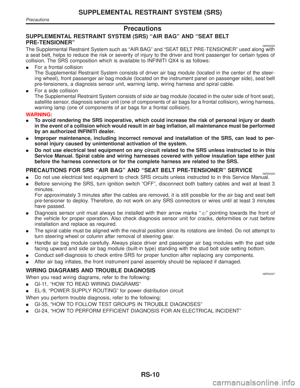
Precautions
SUPPLEMENTAL RESTRAINT SYSTEM (SRS) ªAIR BAGº AND ªSEAT BELT
PRE-TENSIONERº
NBRS0005The Supplemental Restraint System such as ªAIR BAGº and ªSEAT BELT PRE-TENSIONERº used along with
a seat belt, helps to reduce the risk or severity of injury to the driver and front passenger for certain types of
collision. The SRS composition which is available to INFINITI QX4 is as follows:
IFor a frontal collision
The Supplemental Restraint System consists of driver air bag module (located in the center of the steer-
ing wheel), front passenger air bag module (located on the instrument panel on passenger side), seat belt
pre-tensioners, a diagnosis sensor unit, warning lamp, wiring harness and spiral cable.
IFor a side collision
The Supplemental Restraint System consists of side air bag module (located in the outer side of front seat),
satellite sensor, diagnosis sensor unit (one of components of air bags for a frontal collision), wiring harness,
warning lamp (one of components of air bags for a frontal collision).
WARNING:
ITo avoid rendering the SRS inoperative, which could increase the risk of personal injury or death
in the event of a collision which would result in air bag inflation, all maintenance must be performed
by an authorized INFINITI dealer.
IImproper maintenance, including incorrect removal and installation of the SRS, can lead to per-
sonal injury caused by unintentional activation of the system.
IDo not use electrical test equipment on any circuit related to the SRS unless instructed to in this
Service Manual. Spiral cable and wiring harnesses covered with yellow insulation tape either just
before the harness connectors or for the complete harness are related to the SRS.
PRECAUTIONS FOR SRS ªAIR BAGº AND ªSEAT BELT PRE-TENSIONERº SERVICENBRS0006IDo not use electrical test equipment to check SRS circuits unless instructed to in this Service Manual.
IBefore servicing the SRS, turn ignition switch ªOFFº, disconnect both battery cables and wait at least 3
minutes.
For approximately 3 minutes after the cables are removed, it is still possible for the air bag and seat belt
pre-tensioner to deploy. Therefore, do not work on any SRS connectors or wires until at least 3 minutes
have passed.
IDiagnosis sensor unit must always be installed with their arrow marks ªgº pointing towards the front of
the vehicle for proper operation. Also check diagnosis sensor unit for cracks, deformities or rust before
installation and replace as required.
IThe spiral cable must be aligned with the neutral position since its rotations are limited. Do not attempt to
turn steering wheel or column after removal of steering gear.
IHandle air bag module carefully. Always place driver and passenger air bag modules with the pad side
facing upward and side air bag module (built-in type) standing with the stud bolt side setting bottom.
IConduct self-diagnosis to check entire SRS for proper function after replacing any components.
IAfter air bag inflates, the front instrument panel assembly should be replaced if damaged.
WIRING DIAGRAMS AND TROUBLE DIAGNOSISNBRS0007When you read wiring diagrams, refer to the following:
IGI-11, ªHOW TO READ WIRING DIAGRAMSº
IEL-9, ªPOWER SUPPLY ROUTINGº for power distribution circuit
When you perform trouble diagnosis, refer to the following:
IGI-35, ªHOW TO FOLLOW TEST GROUPS IN TROUBLE DIAGNOSESº
IGI-24, ªHOW TO PERFORM EFFICIENT DIAGNOSIS FOR AN ELECTRICAL INCIDENTº
SUPPLEMENTAL RESTRAINT SYSTEM (SRS)
Precautions
RS-10
Page 2124 of 2395

Wiring Diagram Ð SRS ÐNBRS0043
MRS326A
GI
MA
EM
LC
EC
FE
AT
TF
PD
AX
SU
BR
ST
BT
HA
SC
EL
IDX
SUPPLEMENTAL RESTRAINT SYSTEM (SRS)
Wiring Diagram Ð SRS Ð
RS-35
Page 2125 of 2395

MRS282A
SUPPLEMENTAL RESTRAINT SYSTEM (SRS)
Wiring Diagram Ð SRS Ð (Cont'd)
RS-36
Page 2126 of 2395

MRS327A
GI
MA
EM
LC
EC
FE
AT
TF
PD
AX
SU
BR
ST
BT
HA
SC
EL
IDX
SUPPLEMENTAL RESTRAINT SYSTEM (SRS)
Wiring Diagram Ð SRS Ð (Cont'd)
RS-37
Page 2152 of 2395
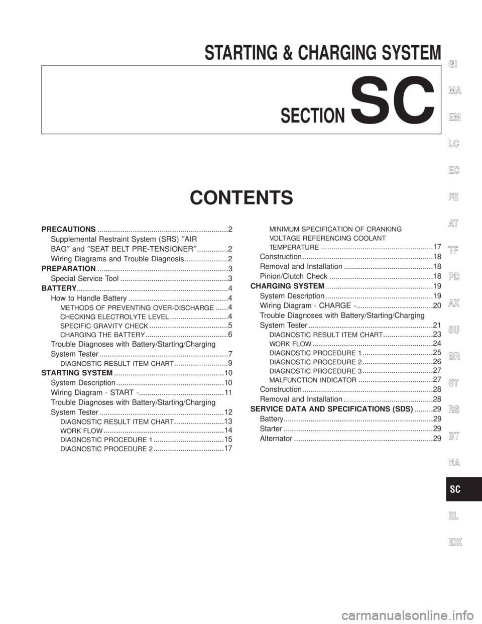
STARTING & CHARGING SYSTEM
SECTION
SC
CONTENTS
PRECAUTIONS...............................................................2
Supplemental Restraint System (SRS)²AIR
BAG²and²SEAT BELT PRE-TENSIONER²...............2
Wiring Diagrams and Trouble Diagnosis .....................2
PREPARATION...............................................................3
Special Service Tool ....................................................3
BATTERY.........................................................................4
How to Handle Battery ................................................4
METHODS OF PREVENTING OVER-DISCHARGE......4
CHECKING ELECTROLYTE LEVEL............................4
SPECIFIC GRAVITY CHECK......................................5
CHARGING THE BATTERY........................................6
Trouble Diagnoses with Battery/Starting/Charging
System Tester ..............................................................7
DIAGNOSTIC RESULT ITEM CHART..........................9
STARTING SYSTEM.....................................................10
System Description ....................................................10
Wiring Diagram - START -......................................... 11
Trouble Diagnoses with Battery/Starting/Charging
System Tester ............................................................12
DIAGNOSTIC RESULT ITEM CHART........................13
WORK FLOW..........................................................14
DIAGNOSTIC PROCEDURE 1..................................15
DIAGNOSTIC PROCEDURE 2..................................17
MINIMUM SPECIFICATION OF CRANKING
VOLTAGE REFERENCING COOLANT
TEMPERATURE
......................................................17
Construction ...............................................................18
Removal and Installation ...........................................18
Pinion/Clutch Check ..................................................18
CHARGING SYSTEM....................................................19
System Description ....................................................19
Wiring Diagram - CHARGE -.....................................20
Trouble Diagnoses with Battery/Starting/Charging
System Tester ............................................................21
DIAGNOSTIC RESULT ITEM CHART........................23
WORK FLOW..........................................................24
DIAGNOSTIC PROCEDURE 1..................................25
DIAGNOSTIC PROCEDURE 2..................................26
DIAGNOSTIC PROCEDURE 3..................................27
MALFUNCTION INDICATOR....................................27
Construction ...............................................................28
Removal and Installation ...........................................28
SERVICE DATA AND SPECIFICATIONS (SDS).........29
Battery........................................................................29
Starter ........................................................................29
Alternator ...................................................................29
GI
MA
EM
LC
EC
FE
AT
TF
PD
AX
SU
BR
ST
RS
BT
HA
EL
IDX
Page 2153 of 2395
Supplemental Restraint System (SRS) ªAIR
BAGº and ªSEAT BELT PRE-TENSIONERº
NBSC0001The Supplemental Restraint System such as ªAIR BAGº and ªSEAT BELT PRE-TENSIONERº used along with
a seat belt, helps to reduce the risk or severity of injury to the driver and front passenger for certain types of
collision. The SRS system composition which is available to INFINITI QX4 is as follows:
IFor a frontal collision
The Supplemental Restraint System consists of driver air bag module (located in the center of the steer-
ing wheel), front passenger air bag module (located on the instrument panel on passenger side), seat belt
pre-tensioners, a diagnosis sensor unit, warning lamp, wiring harness and spiral cable.
IFor a side collision
The Supplemental Restraint System consists of side air bag module (located in the outer side of front seat),
satellite sensor, diagnosis sensor unit (one of components of air bags for a frontal collision), wiring harness,
warning lamp (one of components of air bags for a frontal collision).
Information necessary to service the system safely is included in theRS sectionof this Service Manual.
WARNING:
ITo avoid rendering the SRS inoperative, which could increase the risk of personal injury or death
in the event of a collision which would result in air bag inflation, all maintenance must be performed
by an authorized INFINITI dealer.
IImproper maintenance, including incorrect removal and installation of the SRS, can lead to per-
sonal injury caused by unintentional activation of the system. For removal of Spiral Cable and Air
Bag Module, see the RS section.
IDo not use electrical test equipment on any circuit related to the SRS unless instructed to in this
Service Manual. Spiral cable and wiring harnesses covered with yellow insulation tape either just
before the harness connectors or for the complete harness are related to the SRS.
Wiring Diagrams and Trouble DiagnosisNBSC0002When you read wiring diagrams, refer to the following:
IGI-11, ªHOW TO READ WIRING DIAGRAMSº
IEL-9, ªPOWER SUPPLY ROUTINGº for power distribution circuit
When you perform trouble diagnosis, refer to the following:
IGI-35, ªHOW TO FOLLOW TEST GROUP IN TROUBLE DIAGNOSISº
IGI-24, ªHOW TO PERFORM EFFICIENT DIAGNOSIS FOR AN ELECTRICAL INCIDENTº
PRECAUTIONS
Supplemental Restraint System (SRS) ªAIR BAGº and ªSEAT BELT PRE-TENSIONERº
SC-2