hood open INFINITI QX4 2001 Factory Service Manual
[x] Cancel search | Manufacturer: INFINITI, Model Year: 2001, Model line: QX4, Model: INFINITI QX4 2001Pages: 2395, PDF Size: 43.2 MB
Page 474 of 2395

BODY & TRIM
SECTION
BT
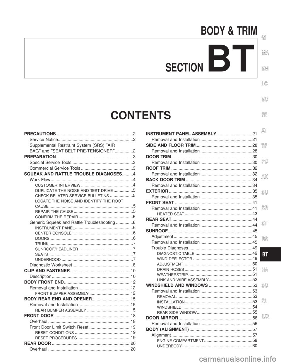
CONTENTS
PRECAUTIONS...............................................................2
Service Notice..............................................................2
Supplemental Restraint System (SRS)²AIR
BAG²and²SEAT BELT PRE-TENSIONER²...............2
PREPARATION...............................................................3
Special Service Tools ..................................................3
Commercial Service Tools ...........................................3
SQUEAK AND RATTLE TROUBLE DIAGNOSES.........4
Work Flow ....................................................................4
CUSTOMER INTERVIEW...........................................4
DUPLICATE THE NOISE AND TEST DRIVE................5
CHECK RELATED SERVICE BULLETINS...................5
LOCATE THE NOISE AND IDENTIFY THE ROOT
CAUSE
.....................................................................5
REPAIR THE CAUSE.................................................5
CONFIRM THE REPAIR.............................................6
Generic Squeak and Rattle Troubleshooting ..............6
INSTRUMENT PANEL................................................6
CENTER CONSOLE..................................................6
DOORS.....................................................................6
TRUNK.....................................................................7
SUNROOF/HEADLINER.............................................7
SEATS......................................................................7
UNDERHOOD...........................................................7
Diagnostic Worksheet ..................................................8
CLIP AND FASTENER..................................................10
Description .................................................................10
BODY FRONT END.......................................................12
Removal and Installation ...........................................12
FRONT BUMPER ASSEMBLY..................................12
BODY REAR END AND OPENER................................15
Removal and Installation ...........................................15
REAR BUMPER ASSEMBLY....................................15
FRONT DOOR...............................................................18
Overhaul ....................................................................18
Front Door Limit Switch Reset ..................................19
RESET CONDITIONS..............................................19
RESET PROCEDURES............................................19
REAR DOOR.................................................................20
Overhaul ....................................................................20INSTRUMENT PANEL ASSEMBLY.............................21
Removal and Installation ...........................................21
SIDE AND FLOOR TRIM...............................................28
Removal and Installation ...........................................28
DOOR TRIM...................................................................30
Removal and Installation ...........................................30
ROOF TRIM...................................................................32
Removal and Installation ...........................................32
BACK DOOR TRIM.......................................................34
Removal and Installation ...........................................34
EXTERIOR.....................................................................35
Removal and Installation ...........................................35
FRONT SEAT................................................................41
Removal and Installation ...........................................41
HEATED SEAT........................................................43
REAR SEAT...................................................................44
Removal and Installation ...........................................44
SUNROOF......................................................................45
Adjustment .................................................................45
Removal and Installation ...........................................45
Trouble Diagnoses.....................................................49
DIAGNOSTIC TABLE................................................49
WIND DEFLECTOR.................................................49
ADJUSTMENT.........................................................50
DRAIN HOSES........................................................51
WEATHERSTRIP.....................................................51
LINK AND WIRE ASSEMBLY....................................52
WINDSHIELD AND WINDOWS....................................53
Removal and Installation ...........................................53
REMOVAL...............................................................53
INSTALLATION........................................................53
WINDSHIELD..........................................................54
REAR SIDE WINDOW..............................................55
DOOR MIRROR.............................................................56
Removal and Installation ...........................................56
BODY (ALIGNMENT)....................................................57
Alignment ...................................................................57
ENGINE COMPARTMENT........................................58
UNDERBODY..........................................................60
GI
MA
EM
LC
EC
FE
AT
TF
PD
AX
SU
BR
ST
RS
HA
SC
EL
IDX
Page 485 of 2395

Removal and InstallationNBBT0004IWhen removing or installing hood, place a cloth or other padding on front fender panel and cowl top. This
prevents vehicle body from being scratched.
IBumper fascia is made of plastic. Do not use excessive force and be sure to keep oil away from it.
IHood adjustment: Adjust at hinge portion.
IHood lock adjustment: After adjusting, check hood lock control operation. Apply a coat of grease to hood
locks engaging mechanism.
IHood opener: Do not attempt to bend cable forcibly. Doing so increases effort required to unlock hood.
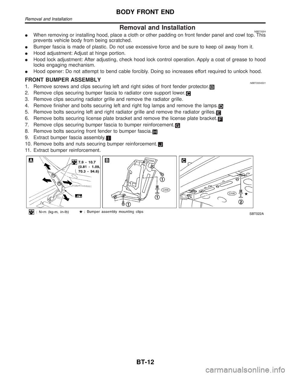
FRONT BUMPER ASSEMBLYNBBT0004S011. Remove screws and clips securing left and right sides of front fender protector.
2. Remove clips securing bumper fascia to radiator core support lower.
3. Remove clips securing radiator grille and remove the radiator grille.
4. Remove finisher and bolts securing left and right fog lamps and remove the lamps.
5. Remove bolts securing left and right radiator grille and remove the radiator grilles.
6. Remove bolts securing license plate bracket and remove the license plate bracket.
7. Remove clips securing bumper fascia to bumper reinforcement.
8. Remove bolts securing front fender to bumper fascia.
9. Extract bumper fascia assembly.
10. Remove bolts and nuts securing bumper reinforcement.
11. Extract bumper reinforcement.
SBT022A
BODY FRONT END
Removal and Installation
BT-12
Page 581 of 2395

INSPECTION PROCEDURE=NBEC0028S02
1 INSPECTION START
1. Visually check the following:
IAir cleaner clogging
IHoses and ducts for leaks
IElectrical connectors
IGasket
IThrottle valve and throttle position sensor operation
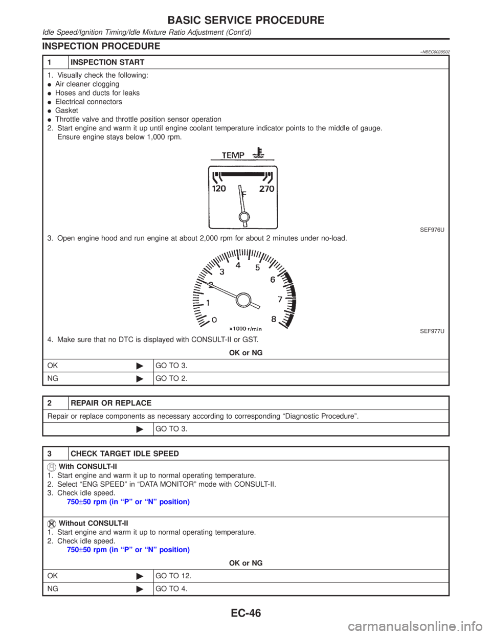
2. Start engine and warm it up until engine coolant temperature indicator points to the middle of gauge.
Ensure engine stays below 1,000 rpm.
SEF976U
3. Open engine hood and run engine at about 2,000 rpm for about 2 minutes under no-load.
SEF977U
4. Make sure that no DTC is displayed with CONSULT-II or GST.
OK or NG
OK©GO TO 3.
NG©GO TO 2.
2 REPAIR OR REPLACE
Repair or replace components as necessary according to corresponding ªDiagnostic Procedureº.
©GO TO 3.
3 CHECK TARGET IDLE SPEED
With CONSULT-II
1. Start engine and warm it up to normal operating temperature.
2. Select ªENG SPEEDº in ªDATA MONITORº mode with CONSULT-II.
3. Check idle speed.
750±50 rpm (in ªPº or ªNº position)
Without CONSULT-II
1. Start engine and warm it up to normal operating temperature.
2. Check idle speed.
750±50 rpm (in ªPº or ªNº position)
OK or NG
OK©GO TO 12.
NG©GO TO 4.
BASIC SERVICE PROCEDURE
Idle Speed/Ignition Timing/Idle Mixture Ratio Adjustment (Cont'd)
EC-46
Page 636 of 2395

Basic InspectionNBEC0038Precaution:
Perform Basic Inspection without electrical or mechanical
loads applied;
IHeadlamp switch is OFF,
IAir conditioner switch is OFF,
IRear window defogger switch is OFF,
ISteering wheel is in the straight-ahead position, etc.
1 INSPECTION START
1. Check service records for any recent repairs that may indicate a related problem, or a current need for scheduled
maintenance.
2. Open engine hood and check the following:
IHarness connectors for improper connections
IVacuum hoses for splits, kinks and improper connections
IWiring for improper connections, pinches and cuts
IAir cleaner clogging
IHoses and ducts for leaks
SEF983U
©GO TO 2.
2 CHECK THROTTLE OPENER OPERATION-I
Confirm that there is a clearance between throttle drum and stopper.
SEF950Y
OK or NG
OK©GO TO 4.
NG©GO TO 3.
GI
MA
EM
LC
FE
AT
TF
PD
AX
SU
BR
ST
RS
BT
HA
SC
EL
IDX
TROUBLE DIAGNOSIS Ð BASIC INSPECTION
Basic Inspection
EC-101
Page 783 of 2395

Possible CauseNBEC0438IHarness or connectors
(The sensor circuit is open or shorted.)
IHeated oxygen sensor 2 (rear)
IFuel pressure
IInjectors
SEF340Z
SEF341Z
SEF342Z
DTC Confirmation ProcedureNBEC0134NOTE:
If ªDTC Confirmation Procedureº has been previously conducted,
always turn ignition switch ªOFFº and wait at least 10 seconds
before conducting the next test.
TESTING CONDITION:
Open engine hood before conducting following procedure.
WITH CONSULT-IINBEC0134S011) Start engine and warm it up to normal operating temperature.
2) Turn ignition switch ªOFFº and wait at least 10 seconds.
3) Turn ignition switch ªONº.
4) Select ªDATA MONITORº mode with CONSULT-II.
5) Make sure that ªCOOLAN TEMP/Sº indicates more than 70ÉC
(158ÉF).
6) Select ªHO2S2 (B1)/(B2) P0137/P0157º of ªHO2S2º in ªDTC
WORK SUPPORTº mode with CONSULT-II.
7) Start engine and follow the instruction of CONSULT-II.
8) Make sure that ªOKº is displayed after touching ªSELF-DIAG
RESULTSº.
If NG is displayed, refer to ªDiagnostic Procedureº, EC-252.
If ªCANNOT BE DIAGNOSEDº is displayed, perform the fol-
lowing.
a) Stop engine and cool down until ªCOOLAN TEMP/Sº indicates
less than 70ÉC (158ÉF).
b) Turn ignition switch ªONº.
c) Select ªDATA MONITORº mode with CONSULT-II.
d) Start engine.
e) Return to step 6 again when the ªCOOLAN TEMP/Sº reaches
to 70ÉC (158ÉF).
SEF312XB
Overall Function CheckNBEC0135Use this procedure to check the overall function of the heated oxy-
gen sensor 2 (rear) circuit. During this check, a 1st trip DTC might
not be confirmed.
WITH GSTNBEC0135S011) Start engine and drive vehicle at a speed of more than 70 km/h
(43 MPH) for 2 consecutive minutes.
2) Stop vehicle with engine running.
3) Set voltmeter probes between ECM terminal 72 (HO2S2 bank
DTC P0137, P0157 HEATED OXYGEN SENSOR 2 (REAR) (BANK 1)/(BANK 2)
(MIN. VOLTAGE MONITORING)
Possible Cause
EC-248
Page 793 of 2395

Possible CauseNBEC0439IHarness or connectors
(The sensor circuit is open or shorted.)
IHeated oxygen sensor 2 (rear)
IFuel pressure
IInjectors
IIntake air leaks
SEF663Y
SEF664Y
SEF665Y
DTC Confirmation ProcedureNBEC0142NOTE:
If ªDTC Confirmation Procedureº has been previously conducted,
always turn ignition switch ªOFFº and wait at least 10 seconds
before conducting the next test.
TESTING CONDITION:
Open engine hood before conducting following procedure.
WITH CONSULT-IINBEC0142S011) Start engine and warm it up to normal operating temperature.
2) Turn ignition switch ªOFFº and wait at least 10 seconds.
3) Turn ignition switch ªONº.
4) Select ªDATA MONITORº mode with CONSULT-II.
5) Make sure that ªCOOLAN TEMP/Sº indicates more than 70ÉC
(158ÉF).
6) Select ªHO2S2 (B1)/(B2) P0138/P0158º of ªHO2S2º in ªDTC
WORK SUPPORTº mode with CONSULT-II.
7) Start engine and follow the instruction of CONSULT-II.
8) Make sure that ªOKº is displayed after touching ªSELF-DIAG
RESULTSº.
If NG is displayed, refer to ªDiagnostic Procedureº, EC-262.
If ªCANNOT BE DIAGNOSEDº is displayed, perform the fol-
lowing.
a) Stop engine and cool down until ªCOOLAN TEMP/Sº indicates
less than 70ÉC (158ÉF).
b) Turn ignition switch ªONº.
c) Select ªDATA MONITORº mode with CONSULT-II.
d) Start engine.
e) Return to step 6 again when the ªCOOLAN TEMP/Sº reaches
to 70ÉC (158ÉF).
SEF312XB
Overall Function CheckNBEC0143Use this procedure to check the overall function of the heated oxy-
gen sensor 2 (rear) circuit. During this check, a 1st trip DTC might
not be confirmed.
WITH GSTNBEC0143S011) Start engine and drive vehicle at a speed of more than 70 km/h
(43 MPH) for 2 consecutive minutes.
2) Stop vehicle with engine running.
3) Set voltmeter probes between ECM terminal 72 (HO2S2 bank
DTC P0138, P0158 HEATED OXYGEN SENSOR 2 (REAR) (BANK 1)/(BANK 2)
(MAX. VOLTAGE MONITORING)
Possible Cause
EC-258
Page 803 of 2395

Possible CauseNBEC0440IHarness or connectors
(The sensor circuit is open or shorted.)
IHeated oxygen sensor 2 (rear)
IFuel pressure
IInjectors
IIntake air leaks
SEF666Y
SEF667Y
SEF668Y
DTC Confirmation ProcedureNBEC0150NOTE:
If ªDTC Confirmation Procedureº has been previously conducted,
always turn ignition switch ªOFFº and wait at least 10 seconds
before conducting the next test.
TESTING CONDITION:
Open engine hood before conducting following procedure.
WITH CONSULT-IINBEC0150S011) Start engine and warm it up to normal operating temperature.
2) Turn ignition switch ªOFFº and wait at least 10 seconds.
3) Turn ignition switch ªONº.
4) Select ªDATA MONITORº mode with CONSULT-II.
5) Make sure that ªCOOLAN TEMP/Sº indicates more than 70ÉC
(158ÉF).
6) Select ªHO2S2 (B1)/(B2) P0139/P0159º of ªHO2S2º in ªDTC
WORK SUPPORTº mode with CONSULT-II.
7) Start engine and follow the instruction of CONSULT-II.
8) Make sure that ªOKº is displayed after touching ªSELF-DIAG
RESULTSº.
If NG is displayed, refer to ªDiagnostic Procedureº, EC-272.
If ªCANNOT BE DIAGNOSEDº is displayed, perform the fol-
lowing.
a) Stop engine and cool down until ªCOOLAN TEMP/Sº indicates
less than 70ÉC (158ÉF).
b) Turn ignition switch ªONº.
c) Select ªDATA MONITORº mode with CONSULT-II.
d) Start engine.
e) Return to step 6 again when the ªCOOLAN TEMP/Sº reaches
to 70ÉC (158ÉF).
SEF312XB
Overall Function CheckNBEC0151Use this procedure to check the overall function of the rear heated
oxygen sensor circuit. During this check, a 1st trip DTC might not
be confirmed.
WITH GSTNBEC0151S011) Start engine and drive vehicle at a speed of more than 70 km/h
(43 MPH) for 2 consecutive minutes.
2) Stop vehicle with engine running.
3) Set voltmeter probes between ECM terminal 72 (HO2S2 bank
DTC P0139, P0159 HEATED OXYGEN SENSOR 2 (REAR) (BANK 1)/(BANK 2)
(RESPONSE MONITORING)
Possible Cause
EC-268
Page 883 of 2395

SEF344Z
DTC Confirmation ProcedureNBEC0215
SEF345Z
SEF560X
NOTE:
If ªDTC Confirmation Procedureº has been previously conducted,
always turn ignition switch ªOFFº and wait at least 10 seconds
before conducting the next test.
WITH CONSULT-IINBEC0215S01TESTING CONDITION:
IOpen engine hood before conducting the following proce-
dure.
IDo not hold engine speed for more than the specified
minutes below.
1) Turn ignition switch ªONº.
2) Select ªDTC & SRT CONFIRMATIONº then ªSRT WORK SUP-
PORTº mode with CONSULT-II.
3) Start engine.
4) Rev engine up to 3,000±500 rpm and hold it for 3 consecutive
minutes then release the accelerator pedal completely.
5) Wait 5 seconds at idle.
6) Rev engine up to 2,500±500 rpm and maintain it until ªINCMPº
of CATALYST changes to ªCMPLTº (It will take approximately
5 minutes).
If not ªCMPLTº, stop engine and cool it down to less than 70ÉC
(158ÉF) and then retest from step 1.
7) Select ªSELF-DIAG RESULTSº mode with CONSULT-II.
8) Confirm that the 1st trip DTC is not detected.
If the 1st trip DTC is detected, go to ªDiagnostic Procedureº,
EC-349.
SEF329X
SEF330X
Overall Function CheckNBEC0216Use this procedure to check the overall function of the warm-up
three way catalyst. During this check, a 1st trip DTC might not be
confirmed.
CAUTION:
Always drive vehicle at a safe speed.
WITH GSTNBEC0216S011) Start engine and drive vehicle at a speed of more than 70 km/h
(43 MPH) for 2 consecutive minutes.
2) Stop vehicle with engine running.
3) Set voltmeters probes between ECM terminals 63 [heated oxy-
gen sensor 1 (front) right bank signal], 62 [heated oxygen
sensor 1 (front) left bank signal] and engine ground, and ECM
terminals 72 [heated oxygen sensor 2 (rear) right bank signal],
71 [heated oxygen sensor 2 (rear) left bank signal] and engine
ground.
4) Keep engine speed at 2,000 rpm constant under no load.
5) Make sure that the voltage switching frequency (high & low)
between ECM terminals 72 and engine ground, or 71 and
engine ground is very less than that of ECM terminals 63 and
engine ground, or 62 and engine ground.
Switching frequency ratio = A/B
DTC P0420 (RIGHT BANK, -B1), P0430 (LEFT BANK, -B2) THREE WAY
CATALYST FUNCTION
DTC Confirmation Procedure
EC-348
Page 889 of 2395

SEF565X
DTC Confirmation ProcedureNBEC0219
SEF566X
SEF874X
SEF567X
NOTE:
IIf DTC P0440 or P1440 is displayed with P1448, perform
trouble diagnosis for DTC P1448 first. (See EC-573.)
IIf ªDTC Confirmation Procedureº has been previously
conducted, always turn ignition switch ªOFFº and wait at least
10 seconds before conducting the next test.
TESTING CONDITION:
IPerform ªDTC WORK SUPPORTº when the fuel level is
between 1/4 to 3/4 full and vehicle is placed on flat level
surface.
IOpen engine hood before conducting the following proce-
dure.
WITH CONSULT-IINBEC0219S011) Turn ignition switch ªONº.
2) Turn ignition switch ªOFFº and wait at least 10 seconds.
3) Turn ignition switch ªONº and select ªDATA MONITORº mode
with CONSULT-II.
4) Make sure that the following conditions are met.
COOLAN TEMP/S: 0 - 70ÉC (32 - 158ÉF)
INT/A TEMP SE: 0 - 30ÉC (32 - 86ÉF)
5) Select ªEVAP SML LEAK P0440/P1440º of ªEVAPORATIVE
SYSTEMº in ªDTC WORK SUPPORTº mode with CONSULT-
II.
Follow the instruction displayed.
NOTE:
If the engine speed cannot be maintained within the range dis-
played on the CONSULT-II screen, go to ªBasic Inspectionº,
EC-101.
6) Make sure that ªOKº is displayed.
If ªNGº is displayed, refer to ªDiagnostic Procedureº, EC-355.
NOTE:
Make sure that EVAP hoses are connected to EVAP canister
purge volume control solenoid valve properly.
WITH GSTNBEC0219S02NOTE:
Be sure to read the explanation of ªDriving Patternº on EC-66
before driving vehicle.
1) Start engine.
2) Drive vehicle according to ªDriving Patternº, EC-66.
3) Stop vehicle.
4) Select ªMODE 1º with GST.
IIf SRT of EVAP system is not set yet, go to the following step.
IIf SRT of EVAP system is set, the result will be OK.
5) Turn ignition switch ªOFFº and wait at least 10 seconds.
6) Start engine.
It is not necessary to cool engine down before driving.
7) Drive vehicle again according to the ªDriving Patternº, EC-66.
8) Stop vehicle.
9) Select ªMODE 3º with GST.
IIf P0440 or P1440 is displayed on the screen, go to ªDiagnos-
tic Procedureº, EC-355.
IIf P1447 is displayed on the screen, go to ªDiagnostic Proce-
dureº for DTC P1447, EC-564.
DTC P0440 EVAP CONTROL SYSTEM (SMALL LEAK) (NEGATIVE PRESSURE)
DTC Confirmation Procedure
EC-354
Page 931 of 2395

SEF565X
DTC Confirmation ProcedureNBEC0646
SEF566X
SEF874X
SEF567X
CAUTION:
Never remove fuel filler cap during the DTC Confirmation Pro-
cedure.
NOTE:
IIf DTC P0455 is displayed with P1448, perform trouble
diagnosis for DTC P1448 first. (See EC-573.)
IMake sure that EVAP hoses are connected to EVAP canis-
ter purge volume control solenoid valve properly.
IIf ªDTC Confirmation Procedureº has been previously
conducted, always turn ignition switch ªOFFº and wait at least
10 seconds before conducting the next test.
TESTING CONDITION:
IPerform ªDTC WORK SUPPORTº when the fuel level is
between 1/4 to 3/4 full and vehicle is placed on flat level
surface.
IOpen engine hood before conducting the following proce-
dures.
WITH CONSULT-IINBEC0646S011) Tighten fuel filler cap securely until ratcheting sound is heard.
2) Turn ignition switch ªONº.
3) Turn ignition switch ªOFFº and wait at least 10 seconds.
4) Turn ignition switch ªONº and select ªDATA MONITORº mode
with CONSULT-II.
5) Make sure that the following conditions are met.
COOLAN TEMP/S: 0 - 70ÉC (32 - 158ÉF)
INT/A TEMP SE: 0 - 60ÉC (32 - 140ÉF)
6) Select ªEVAP SML LEAK P0440/P1440º of ªEVAPORATIVE
SYSTEMº in ªDTC WORK SUPPORTº mode with CONSULT-
II.
Follow the instruction displayed.
NOTE:
If the engine speed cannot be maintained within the range dis-
played on the CONSULT-II screen, go to ªBasic Inspectionº,
EC-101.
7) Make sure that ªOKº is displayed.
If ªNGº is displayed, select ªSELF-DIAG RESULTSº mode and
make sure that ªEVAP GROSS LEAK [P0455]º is displayed. If
it is displayed, refer to ªDiagnostic Procedureº, EC-397.
If P0440 is displayed, perform ªDiagnostic Procedureº for DTC
P0440.
WITH GSTNBEC0646S02NOTE:
Be sure to read the explanation of ªDriving Patternº on EC-66
before driving vehicle.
1) Start engine.
2) Drive vehicle according to ªDriving Patternº, EC-66.
3) Stop vehicle.
4) Select ªMODE 1º with GST.
IIf SRT of EVAP system is not set yet, go to the following step.
IIf SRT of EVAP system is set, the result will be OK.
5) Turn ignition switch ªOFFº and wait at least 10 seconds.
6) Start engine.
It is not necessary to cool engine down before driving.
7) Drive vehicle again according to the ªDriving Patternº, EC-66.
DTC P0455 EVAP CONTROL SYSTEM (GROSS LEAK)
DTC Confirmation Procedure
EC-396