Electrical INFINITI QX4 2001 Factory Owner's Guide
[x] Cancel search | Manufacturer: INFINITI, Model Year: 2001, Model line: QX4, Model: INFINITI QX4 2001Pages: 2395, PDF Size: 43.2 MB
Page 671 of 2395

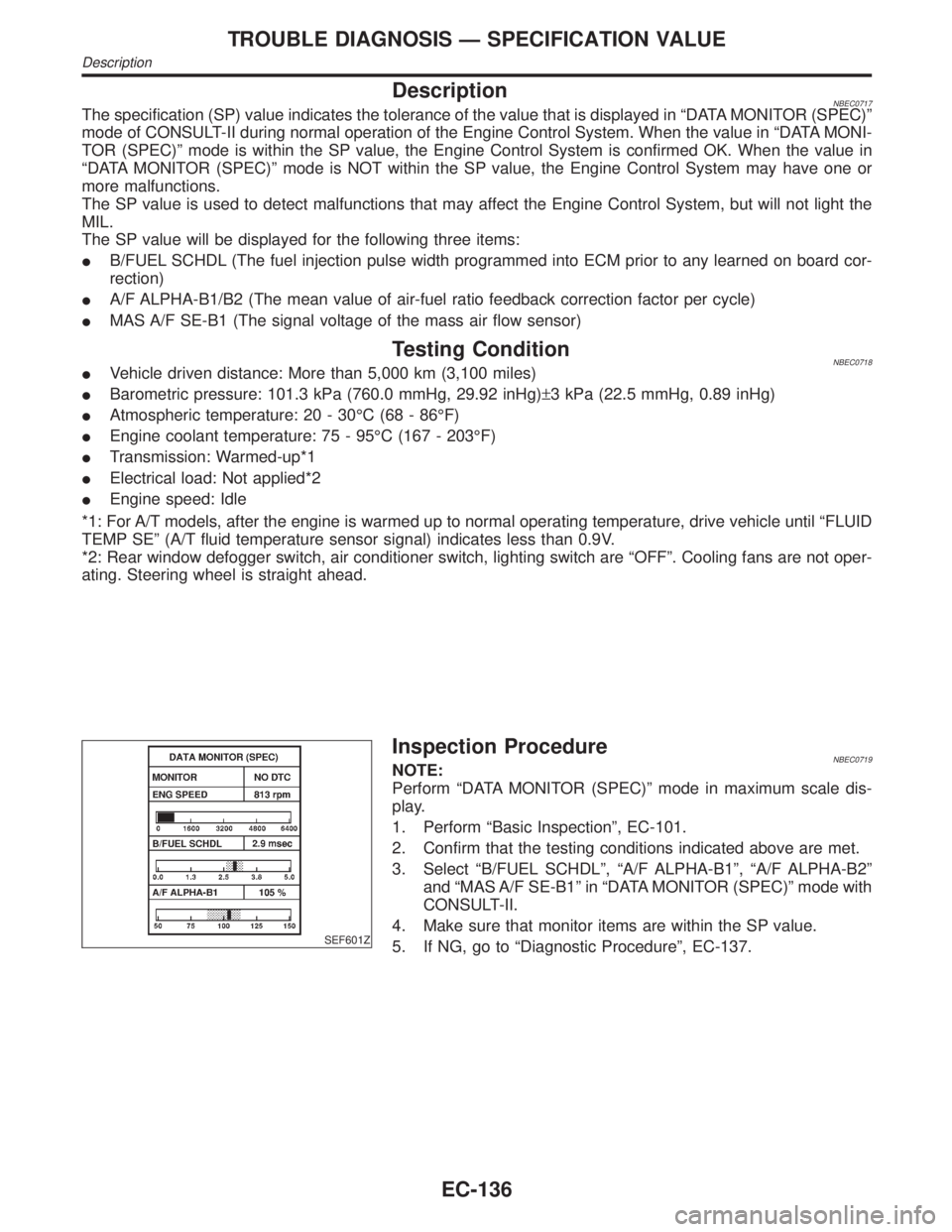
DescriptionNBEC0717The specification (SP) value indicates the tolerance of the value that is displayed in ªDATA MONITOR (SPEC)º
mode of CONSULT-II during normal operation of the Engine Control System. When the value in ªDATA MONI-
TOR (SPEC)º mode is within the SP value, the Engine Control System is confirmed OK. When the value in
ªDATA MONITOR (SPEC)º mode is NOT within the SP value, the Engine Control System may have one or
more malfunctions.
The SP value is used to detect malfunctions that may affect the Engine Control System, but will not light the
MIL.
The SP value will be displayed for the following three items:
IB/FUEL SCHDL (The fuel injection pulse width programmed into ECM prior to any learned on board cor-
rection)
IA/F ALPHA-B1/B2 (The mean value of air-fuel ratio feedback correction factor per cycle)
IMAS A/F SE-B1 (The signal voltage of the mass air flow sensor)
Testing ConditionNBEC0718IVehicle driven distance: More than 5,000 km (3,100 miles)
IBarometric pressure: 101.3 kPa (760.0 mmHg, 29.92 inHg)±3 kPa (22.5 mmHg, 0.89 inHg)
IAtmospheric temperature: 20 - 30ÉC (68 - 86ÉF)
IEngine coolant temperature: 75 - 95ÉC (167 - 203ÉF)
ITransmission: Warmed-up*1
IElectrical load: Not applied*2
IEngine speed: Idle
*1: For A/T models, after the engine is warmed up to normal operating temperature, drive vehicle until ªFLUID
TEMP SEº (A/T fluid temperature sensor signal) indicates less than 0.9V.
*2: Rear window defogger switch, air conditioner switch, lighting switch are ªOFFº. Cooling fans are not oper-
ating. Steering wheel is straight ahead.
SEF601Z
Inspection ProcedureNBEC0719NOTE:
Perform ªDATA MONITOR (SPEC)º mode in maximum scale dis-
play.
1. Perform ªBasic Inspectionº, EC-101.
2. Confirm that the testing conditions indicated above are met.
3. Select ªB/FUEL SCHDLº, ªA/F ALPHA-B1º, ªA/F ALPHA-B2º
and ªMAS A/F SE-B1º in ªDATA MONITOR (SPEC)º mode with
CONSULT-II.
4. Make sure that monitor items are within the SP value.
5. If NG, go to ªDiagnostic Procedureº, EC-137.
TROUBLE DIAGNOSIS Ð SPECIFICATION VALUE
Description
EC-136
Page 675 of 2395

DescriptionNBEC0045Intermittent incidents (I/I) may occur. In many cases, the problem resolves itself (the part or circuit function
returns to normal without intervention). It is important to realize that the symptoms described in the custom-
er's complaint often do not recur on (1st trip) DTC visits. Realize also that the most frequent cause of I/I
occurrences is poor electrical connections. Because of this, the conditions under which the incident occurred
may not be clear. Therefore, circuit checks made as part of the standard diagnostic procedure may not indi-
cate the specific problem area.
COMMON I/I REPORT SITUATIONSNBEC0045S01
STEP in Work Flow Situation
II The CONSULT-II is used. The SELF-DIAG RESULTS screen shows time data other than ª0º or ª[1t]º.
III The symptom described by the customer does not recur.
IV (1st trip) DTC does not appear during the DTC Confirmation Procedure.
VI The Diagnostic Procedure for PXXXX does not indicate the problem area.
Diagnostic ProcedureNBEC0046
1 INSPECTION START
Erase (1st trip) DTCs. Refer to ªHOW TO ERASE EMISSION Ð RELATED INFORMATIONº, EC-72.
©GO TO 2.
2 CHECK GROUND TERMINALS
Check ground terminals for corroding or loose connection.
Refer to GI-30, ªGROUND INSPECTIONº.
OK or NG
OK©GO TO 3.
NG©Repair or replace.
3 SEARCH FOR ELECTRICAL INCIDENT
Perform GI-36, ªIncident Simulation Testsº.
OK or NG
OK©GO TO 4.
NG©Repair or replace.
4 CHECK CONNECTOR TERMINALS
Refer to GI-27, ªHow to Check Enlarged Contact Spring of Terminalº.
OK or NG
OK©INSPECTION END
NG©Repair or replace connector.
TROUBLE DIAGNOSIS FOR INTERMITTENT INCIDENT
Description
EC-140
Page 699 of 2395

SEF962Y
SEF012P
Component DescriptionNBEC0064The intake air temperature sensor is mounted to the air duct hous-
ing. The sensor detects intake air temperature and transmits a sig-
nal to the ECM.
The temperature sensing unit uses a thermistor which is sensitive
to the change in temperature. Electrical resistance of the thermistor
decreases in response to the temperature rise.
Intake air
temperature ÉC (ÉF)Voltage* V Resistance kW
20 (68) 3.5 2.1 - 2.9
80 (176) 1.23 0.27 - 0.38
*: These data are reference values and are measured between ECM terminal 64
(Intake air temperature sensor) and body ground.
CAUTION:
Do not use ECM ground terminals when measuring input/
output voltage. Doing so may result in damage to the ECM's
transistor. Use a ground other than ECM terminals, such as
the ground.
On Board Diagnosis LogicNBEC0065Malfunction is detected when
(Malfunction A)an excessively low or high voltage from the sen-
sor is sent to ECM,
(Malfunction B)rationally incorrect voltage from the sensor is sent
to ECM, compared with the voltage signal from engine coolant
temperature sensor.
Possible CauseNBEC0428IHarness or connectors
(The sensor circuit is open or shorted.)
IIntake air temperature sensor
DTC Confirmation ProcedureNBEC0066Perform ªPROCEDURE FOR MALFUNCTION Aº first. If 1st trip
DTC cannot be confirmed, perform ªPROCEDURE FOR MAL-
FUNCTION Bº.
NOTE:
If ªDTC Confirmation Procedureº has been previously conducted,
always turn ignition switch ªOFFº and wait at least 10 seconds
before conducting the next test.
DTC P0110 INTAKE AIR TEMPERATURE SENSOR
Component Description
EC-164
Page 704 of 2395

SEF594K
Component DescriptionNBEC0069The engine coolant temperature sensor is used to detect the
engine coolant temperature. The sensor modifies a voltage signal
from the ECM. The modified signal returns to the ECM as the
engine coolant temperature input. The sensor uses a thermistor
which is sensitive to the change in temperature. The electrical
resistance of the thermistor decreases as temperature increases.
SEF012P
Engine coolant
temperature ÉC (ÉF)Voltage* V Resistance kW
þ10 (14) 4.4 7.0 - 11.4
20 (68) 3.5 2.1 - 2.9
50 (122) 2.2 0.68 - 1.00
90 (194) 0.9 0.236 - 0.260
*: These data are reference values and are measured between ECM terminal 70
(Engine coolant temperature sensor) and ground.
CAUTION:
Do not use ECM ground terminals when measuring input/
output voltage. Doing so may result in damage to the ECM's
transistor. Use a ground other than ECM terminals, such as
the ground.
On Board Diagnosis LogicNBEC0070Malfunction is detected when an excessively high or low voltage
from the sensor is sent to ECM.
FAIL-SAFE MODENBEC0070S02When this malfunction is detected, the ECM enters fail-safe mode
and the MIL lights up.
Detected items Engine operating condition in fail-safe mode
Engine coolant tem-
perature sensor circuitEngine coolant temperature will be determined by ECM based on the time after turning ignition switch
ªONº or ªSTARTº.
CONSULT-II displays the engine coolant temperature decided by ECM.
ConditionEngine coolant temperature decided (CONSULT-II
display)
Just as ignition switch is turned ON or Start 40ÉC (104ÉF)
More than approx. 4 minutes after ignition ON or
Start80ÉC (176ÉF)
Except as shown above40 - 80ÉC (104 - 176ÉF)
(Depends on the time)
GI
MA
EM
LC
FE
AT
TF
PD
AX
SU
BR
ST
RS
BT
HA
SC
EL
IDX
DTC P0115 ENGINE COOLANT TEMPERATURE SENSOR (ECTS) (CIRCUIT)
Component Description
EC-169
Page 722 of 2395

DescriptionNBEC0081NOTE:
If DTC P0125 is displayed with P0115, first perform the trouble
diagnosis for DTC P0115. Refer to EC-169.
SEF594K
COMPONENT DESCRIPTIONNBEC0081S01The engine coolant temperature sensor is used to detect the
engine coolant temperature. The sensor modifies a voltage signal
from the ECM. The modified signal returns to the ECM as the
engine coolant temperature input. The sensor uses a thermistor
which is sensitive to the change in temperature. The electrical
resistance of the thermistor decreases as temperature increases.
SEF012P
Engine coolant
temperature ÉC (ÉF)Voltage* V Resistance kW
þ10 (14) 4.4 9.2
20 (68) 3.5 2.1 - 2.9
50 (122) 2.2 0.68 - 1.00
90 (194) 0.9 0.236 - 0.260
*: These data are reference values and are measured between ECM terminal 70
(Engine coolant temperature sensor) and ground.
CAUTION:
Do not use ECM ground terminals when measuring input/
output voltage. Doing so may result in damage to the ECM's
transistor. Use a ground other than ECM terminals, such as
the ground.
On Board Diagnosis LogicNBEC0082Malfunction is detected when voltage sent to ECM from the sen-
sor is not practical, even when some time has passed after start-
ing the engine, or engine coolant temperature is insufficient for
closed loop fuel control.
GI
MA
EM
LC
FE
AT
TF
PD
AX
SU
BR
ST
RS
BT
HA
SC
EL
IDX
DTC P0125 ENGINE COOLANT TEMPERATURE SENSOR (ECTS)
Description
EC-187
Page 844 of 2395

SEF751UA
Component DescriptionNBEC0177The fuel tank temperature sensor is used to detect the fuel tem-
perature inside the fuel tank. The sensor modifies a voltage signal
from the ECM. The modified signal returns to the ECM as the fuel
temperature input. The sensor uses a thermistor which is sensitive
to the change in temperature. The electrical resistance of the ther-
mistor decreases as temperature increases.
SEF012P
Fuel temperature
ÉC (ÉF)Voltage* V Resistance kW
20 (68) 3.5 2.3 - 2.7
50 (122) 2.2 0.79 - 0.90
*: These data are reference values and are measured between ECM terminal 92
(Fuel tank temperature sensor) and body ground.
CAUTION:
Do not use ECM ground terminals when measuring input/
output voltage. Doing so may result in damage to the ECM's
transistor. Use a ground other than ECM terminals, such as
the ground.
On Board Diagnosis LogicNBEC0178Malfunction is detected when an excessively high or low voltage is
sent to ECM, rationally incorrect voltage is sent to ECM, compared
with the voltage signals from engine coolant temperature sensor
and intake air temperature sensor.
Possible CauseNBEC0489IHarness or connectors
(The sensor circuit is open or shorted.)
IFuel tank temperature sensor
GI
MA
EM
LC
FE
AT
TF
PD
AX
SU
BR
ST
RS
BT
HA
SC
EL
IDX
DTC P0180 FUEL TANK TEMPERATURE SENSOR
Component Description
EC-309
Page 1178 of 2395

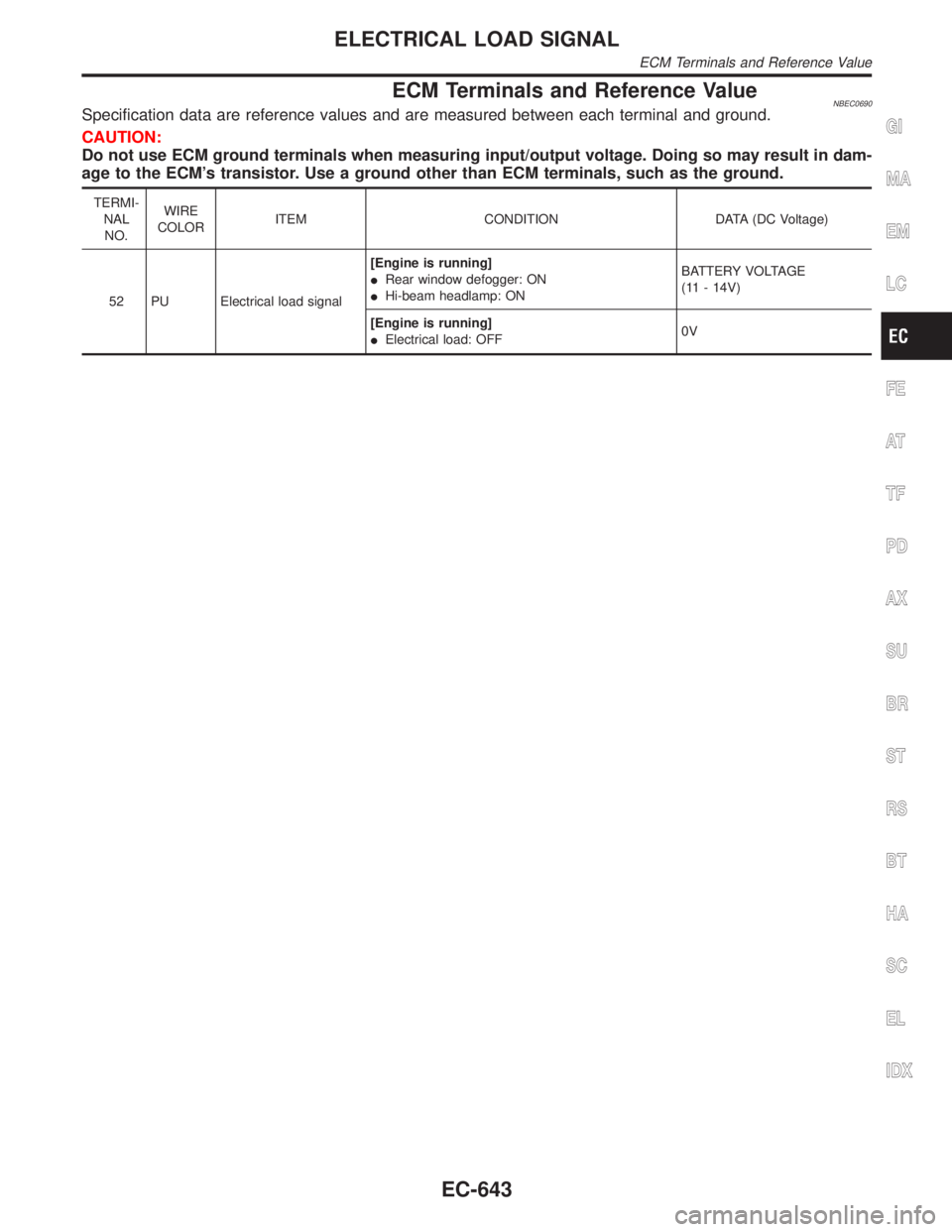
ECM Terminals and Reference ValueNBEC0690Specification data are reference values and are measured between each terminal and ground.
CAUTION:
Do not use ECM ground terminals when measuring input/output voltage. Doing so may result in dam-
age to the ECM's transistor. Use a ground other than ECM terminals, such as the ground.
TERMI-
NAL
NO.WIRE
COLORITEM CONDITION DATA (DC Voltage)
52 PU Electrical load signal[Engine is running]
IRear window defogger: ON
IHi-beam headlamp: ONBATTERY VOLTAGE
(11 - 14V)
[Engine is running]
IElectrical load: OFF0V
GI
MA
EM
LC
FE
AT
TF
PD
AX
SU
BR
ST
RS
BT
HA
SC
EL
IDX
ELECTRICAL LOAD SIGNAL
ECM Terminals and Reference Value
EC-643
Page 1179 of 2395

Wiring DiagramNBEC0604
MEC421D
ELECTRICAL LOAD SIGNAL
Wiring Diagram
EC-644
Page 1180 of 2395

Diagnostic ProcedureNBEC0605
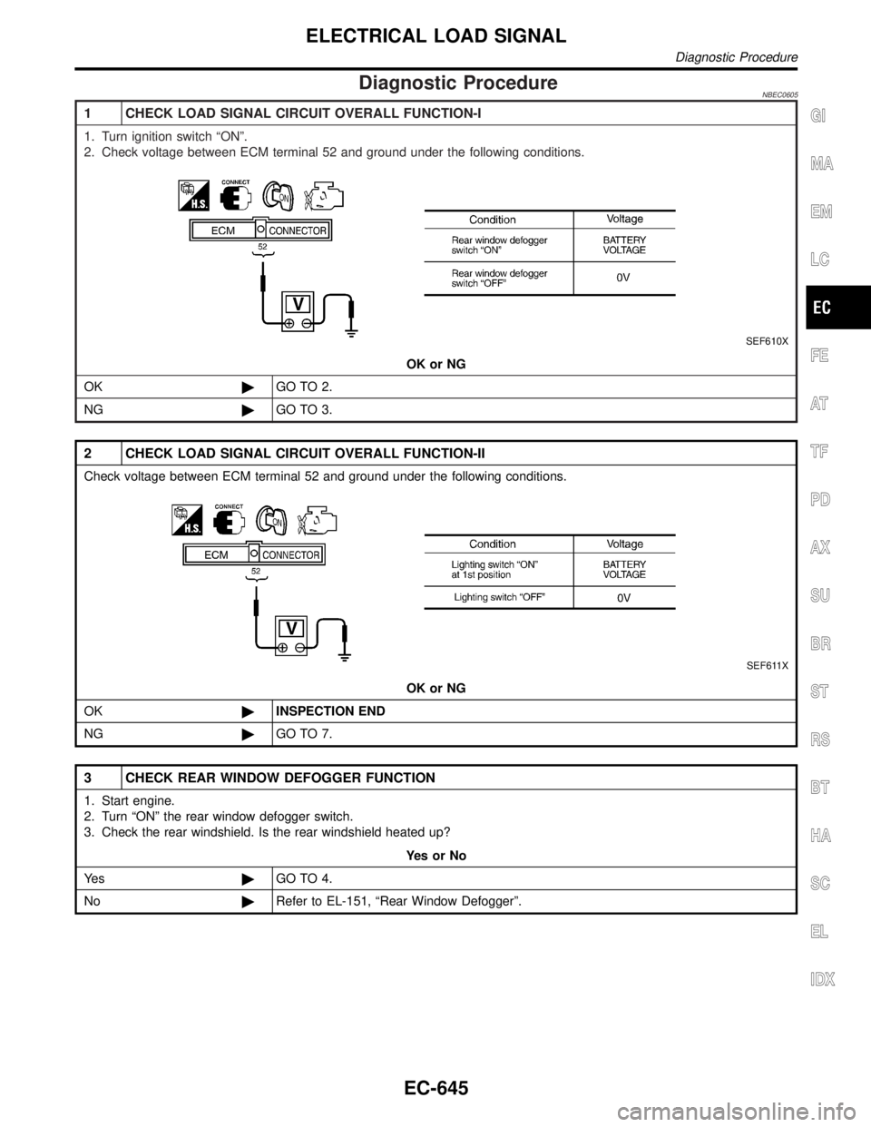
1 CHECK LOAD SIGNAL CIRCUIT OVERALL FUNCTION-I
1. Turn ignition switch ªONº.
2. Check voltage between ECM terminal 52 and ground under the following conditions.
SEF610X
OK or NG
OK©GO TO 2.
NG©GO TO 3.
2 CHECK LOAD SIGNAL CIRCUIT OVERALL FUNCTION-II
Check voltage between ECM terminal 52 and ground under the following conditions.
SEF611X
OK or NG
OK©INSPECTION END
NG©GO TO 7.
3 CHECK REAR WINDOW DEFOGGER FUNCTION
1. Start engine.
2. Turn ªONº the rear window defogger switch.
3. Check the rear windshield. Is the rear windshield heated up?
YesorNo
Ye s©GO TO 4.
No©Refer to EL-151, ªRear Window Defoggerº.
GI
MA
EM
LC
FE
AT
TF
PD
AX
SU
BR
ST
RS
BT
HA
SC
EL
IDX
ELECTRICAL LOAD SIGNAL
Diagnostic Procedure
EC-645
Page 1181 of 2395

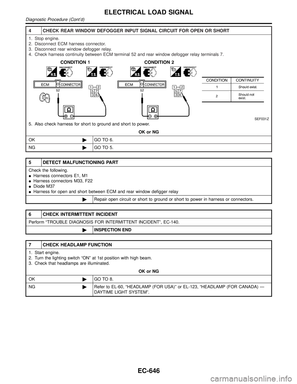
4 CHECK REAR WINDOW DEFOGGER INPUT SIGNAL CIRCUIT FOR OPEN OR SHORT
1. Stop engine.
2. Disconnect ECM harness connector.
3. Disconnect rear window defogger relay.
4. Check harness continuity between ECM terminal 52 and rear window defogger relay terminals 7.
SEF031Z
5. Also check harness for short to ground and short to power.
OK or NG
OK©GO TO 6.
NG©GO TO 5.
5 DETECT MALFUNCTIONING PART
Check the following.
IHarness connectors E1, M1
IHarness connectors M33, F22
IDiode M37
IHarness for open and short between ECM and rear window defigger relay
©Repair open circuit or short to ground or short to power in harness or connectors.
6 CHECK INTERMITTENT INCIDENT
Perform ªTROUBLE DIAGNOSIS FOR INTERMITTENT INCIDENTº, EC-140.
©INSPECTION END
7 CHECK HEADLAMP FUNCTION
1. Start engine.
2. Turn the lighting switch ªONº at 1st position with high beam.
3. Check that headlamps are illuminated.
OK or NG
OK©GO TO 8.
NG©Refer to EL-60, ªHEADLAMP (FOR USA)º or EL-123, ªHEADLAMP (FOR CANADA) Ð
DAYTIME LIGHT SYSTEMº.
ELECTRICAL LOAD SIGNAL
Diagnostic Procedure (Cont'd)
EC-646