center console INFINITI QX4 2001 Factory Service Manual
[x] Cancel search | Manufacturer: INFINITI, Model Year: 2001, Model line: QX4, Model: INFINITI QX4 2001Pages: 2395, PDF Size: 43.2 MB
Page 419 of 2395

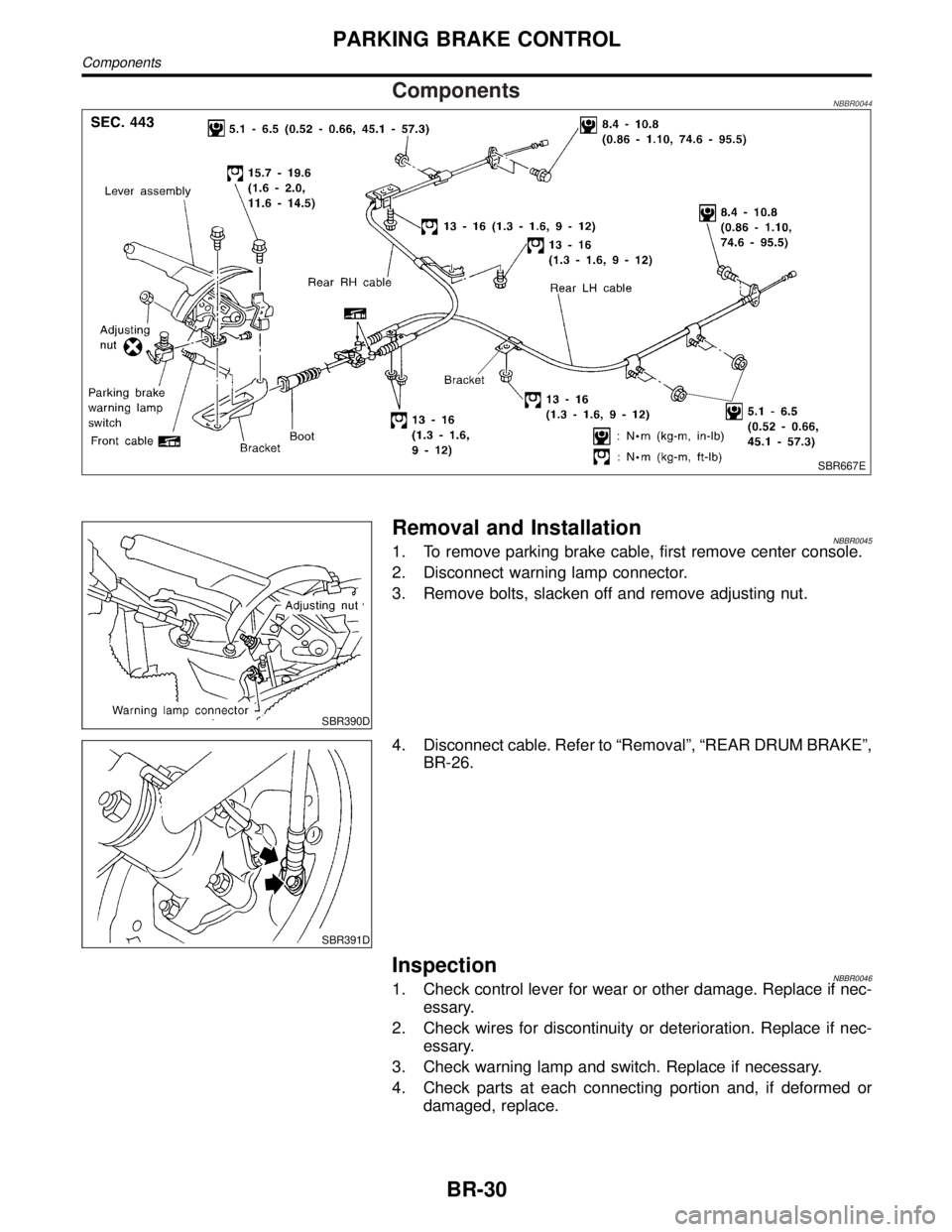
ComponentsNBBR0044
SBR667E
SBR390D
Removal and InstallationNBBR00451. To remove parking brake cable, first remove center console.
2. Disconnect warning lamp connector.
3. Remove bolts, slacken off and remove adjusting nut.
SBR391D
4. Disconnect cable. Refer to ªRemovalº, ªREAR DRUM BRAKEº,
BR-26.
InspectionNBBR00461. Check control lever for wear or other damage. Replace if nec-
essary.
2. Check wires for discontinuity or deterioration. Replace if nec-
essary.
3. Check warning lamp and switch. Replace if necessary.
4. Check parts at each connecting portion and, if deformed or
damaged, replace.
PARKING BRAKE CONTROL
Components
BR-30
Page 474 of 2395

BODY & TRIM
SECTION
BT
CONTENTS
PRECAUTIONS...............................................................2
Service Notice..............................................................2
Supplemental Restraint System (SRS)²AIR
BAG²and²SEAT BELT PRE-TENSIONER²...............2
PREPARATION...............................................................3
Special Service Tools ..................................................3
Commercial Service Tools ...........................................3
SQUEAK AND RATTLE TROUBLE DIAGNOSES.........4
Work Flow ....................................................................4
CUSTOMER INTERVIEW...........................................4
DUPLICATE THE NOISE AND TEST DRIVE................5
CHECK RELATED SERVICE BULLETINS...................5
LOCATE THE NOISE AND IDENTIFY THE ROOT
CAUSE
.....................................................................5
REPAIR THE CAUSE.................................................5
CONFIRM THE REPAIR.............................................6
Generic Squeak and Rattle Troubleshooting ..............6
INSTRUMENT PANEL................................................6
CENTER CONSOLE..................................................6
DOORS.....................................................................6
TRUNK.....................................................................7
SUNROOF/HEADLINER.............................................7
SEATS......................................................................7
UNDERHOOD...........................................................7
Diagnostic Worksheet ..................................................8
CLIP AND FASTENER..................................................10
Description .................................................................10
BODY FRONT END.......................................................12
Removal and Installation ...........................................12
FRONT BUMPER ASSEMBLY..................................12
BODY REAR END AND OPENER................................15
Removal and Installation ...........................................15
REAR BUMPER ASSEMBLY....................................15
FRONT DOOR...............................................................18
Overhaul ....................................................................18
Front Door Limit Switch Reset ..................................19
RESET CONDITIONS..............................................19
RESET PROCEDURES............................................19
REAR DOOR.................................................................20
Overhaul ....................................................................20INSTRUMENT PANEL ASSEMBLY.............................21
Removal and Installation ...........................................21
SIDE AND FLOOR TRIM...............................................28
Removal and Installation ...........................................28
DOOR TRIM...................................................................30
Removal and Installation ...........................................30
ROOF TRIM...................................................................32
Removal and Installation ...........................................32
BACK DOOR TRIM.......................................................34
Removal and Installation ...........................................34
EXTERIOR.....................................................................35
Removal and Installation ...........................................35
FRONT SEAT................................................................41
Removal and Installation ...........................................41
HEATED SEAT........................................................43
REAR SEAT...................................................................44
Removal and Installation ...........................................44
SUNROOF......................................................................45
Adjustment .................................................................45
Removal and Installation ...........................................45
Trouble Diagnoses.....................................................49
DIAGNOSTIC TABLE................................................49
WIND DEFLECTOR.................................................49
ADJUSTMENT.........................................................50
DRAIN HOSES........................................................51
WEATHERSTRIP.....................................................51
LINK AND WIRE ASSEMBLY....................................52
WINDSHIELD AND WINDOWS....................................53
Removal and Installation ...........................................53
REMOVAL...............................................................53
INSTALLATION........................................................53
WINDSHIELD..........................................................54
REAR SIDE WINDOW..............................................55
DOOR MIRROR.............................................................56
Removal and Installation ...........................................56
BODY (ALIGNMENT)....................................................57
Alignment ...................................................................57
ENGINE COMPARTMENT........................................58
UNDERBODY..........................................................60
GI
MA
EM
LC
EC
FE
AT
TF
PD
AX
SU
BR
ST
RS
HA
SC
EL
IDX
Page 479 of 2395

80845-71L00: 30 mm (1.18 in) thick, 30 x 50 mm (1.18 x 1.97 in)
FELT CLOTH TAPE
Used to insulate where movement does not occur. Ideal for instrument panel applications.
68370-4B000: 15 x 25 mm (0.59 x 0.98 in) pad/68239-13E00: 5 mm (0.20 in) wide tape roll
The following materials, not found in the kit, can also be used to repair squeaks and rattles.
UHMW (TEFLON) TAPE
Insulates where slight movement is present. Ideal for instrument panel applications.
SILICONE GREASE
Used in place of UHMW tape that will be visible or not fit.
Note: Will only last a few months.
SILICONE SPRAY
Use when grease cannot be applied.
DUCT TAPE
Use to eliminate movement.
CONFIRM THE REPAIRNBBT0024S06Confirm that the cause of a noise is repaired by test driving the vehicle. Operate the vehicle under the same
conditions as when the noise originally occurred. Refer to the notes on the Diagnostic Worksheet.
Generic Squeak and Rattle TroubleshootingNBBT0025Refer to Table of Contents for specific component removal and installation information.
INSTRUMENT PANELNBBT0025S01Most incidents are caused by contact and movement between:
1. The cluster lid A and instrument panel
2. Acrylic lens and combination meter housing
3. Instrument panel to front pillar garnish
4. Instrument panel to windshield
5. Instrument panel mounting pins
6. Wiring harnesses behind the combination meter
7. A/C defroster duct and duct joint
These incidents can usually be located by tapping or moving the components to duplicate the noise or by
pressing on the components while driving to stop the noise. Most of these incidents can be repaired by apply-
ing felt cloth tape or silicon spray (in hard to reach areas). Urethane pads can be used to insulate wiring har-
ness.
CAUTION:
Do not use silicone spray to isolate a squeak or rattle. If you saturate the area with silicone, you will
not be able to recheck the repair.
CENTER CONSOLENBBT0025S02Components to pay attention to include:
1. Shifter assembly cover to finisher
2. A/C control unit and cluster lid C
3. Wiring harnesses behind audio and A/C control unit
The instrument panel repair and isolation procedures also apply to the center console.
DOORSNBBT0025S03Pay attention to the:
1. Finisher and inner panel making a slapping noise
2. Inside handle escutcheon to door finisher
3. Wiring harnesses tapping
4. Door striker out of alignment causing a popping noise on starts and stops
Tapping or moving the components or pressing on them while driving to duplicate the conditions can isolate
many of these incidents. You can usually insulate the areas with felt cloth tape or insulator foam blocks from
the Nissan Squeak and Rattle Kit (J-43980) to repair the noise.
SQUEAK AND RATTLE TROUBLE DIAGNOSES
Work Flow (Cont'd)
BT-6
Page 1962 of 2395

Brake fluid change ...........................................BR-7
Brake fluid level .............................................MA-25
Brake fluid level and line check .......................BR-7
Brake hydraulic line ..........................................BR-9
Brake inspection ............................................MA-25
Brake lines and cables inspection .................MA-25
Brake lining wear temporary checking ..........MA-26
Brake master cylinder ....................................BR-16
Brake pedal ....................................................BR-14
Bulb specifications ........................................EL-456
Bumper, front ..................................................BT-12
Bumper, rear ...................................................BT-15
BYPS/V - Wiring diagram ....................EC-587, 594
C
Camshaft inspection ......................................EM-42
Camshaft position sensor (PHASE) .............EC-342
Canister-See EVAP canister ..........................EC-32
Center bearing assembly (propeller
shaft) .............................................................PD-9
Center bearing disassembly (propeller
shaft) .............................................................PD-7
Center case (Transfer) ..................................TF-123
CHARGE - Wiring diagram ............................SC-20
Charging system ............................................SC-19
Chassis and body maintenance ....................MA-21
CHIME - Wiring diagram...............................EL-127
CIGAR - Wiring diagram ...............................EL-148
Cigarette lighter.............................................EL-148
Circuit breaker.................................................EL-16
CKPS - Wiring diagram ................................EC-334
Closed loop control (Left bank) ....................EC-491
Closed loop control (Right bank) .................EC-491
Closed throttle position switch .....................EC-431
Clutch drum (Transfer) ..................................TF-125
Clutch force release limit adjustment .............TF-39
Clutch pressure switch (Transfer) .................TF-111
Coil spring (front)..............................................SU-8
Coil spring (rear) ............................................SU-18
Collision diagnosis..........................................RS-59
Combination lamp, front, removal and
installation ...................................................BT-12
Combination lamp, rear, removal and
installation ...................................................BT-35
Combination meter..........................................EL-94
Combination meter removal and instal-
lation - See Instrument panel ......................BT-21
Combination switch .........................................EL-28
COMPAS - Wiring diagram ...........................EL-111
Compass .......................................................EL-110
Component Location (auto A/C).....................HA-27
Compression pressure ...................................EM-14
Compressor clutch removal and
installation .................................................HA-150
Compressor precaution ....................................HA-6
Compressor special service tool ....................HA-10
Connecting rod...............................................EM-65
Connecting rod bearing clearance.................EM-69
Connecting rod bushing clearance ................EM-70Connector inspection .......................................GI-21
Console box - See Instrument panel ..............BT-21
CONSULT for ABS .........................................BR-43
CONSULT for all-mode 4WD ..........................TF-30
CONSULT for engine .....................................EC-81
CONSULT-II general information .....................GI-38
Control valve (A/T) ........................................AT-301
Control valve (Transfer) ................................TF-128
Converter housing installation .......................AT-278
Coolant mixture ratio......................................MA-12
Coolant replacement ......................................MA-14
Cooling circuit (engine) ...................................LC-10
``Crankcase emission control system -
See positive crankcase ventilation''............EC-38
Crankshaft ......................................................EM-67
Crankshaft position sensor (POS) ...............EC-334
Crankshaft position sensor (POS)
chipping ....................................................EC-517
Crankshaft position sensor (REF) ................EC-510
Cruise control - See ASCD ...........................EL-221
Cylinder block ................................................EM-61
Cylinder head .................................................EM-38
Cylinder head bolt tightening .........................EM-49
D
Data link connector for Consult......................EC-81
Daytime light system.......................................EL-46
Daytime running light - See Daytime
light system .................................................EL-46
DEF - Wiring diagram ...................................EL-153
Detonation sensor - See Knock sensor .......EC-328
Diagnostic trouble code (DTC) for OBD
system ....................................................EC-8, 60
Diagnostic trouble code (DTC) inspec-
tion priority chart .......................................EC-116
Differential carrier assembly.....................PD-30, 57
Differential carrier disassembly ......................PD-44
Differential gear oil replacement ....................MA-24
Dimensions ......................................................GI-43
D/LOCK - Wiring diagram .............................EL-256
Dome light - See Interior lamp .......................EL-88
Door glass .......................................................BT-18
Door lock .........................................................BT-18
Door mirror ......................................................BT-56
Door trim .........................................................BT-30
Door, front .......................................................BT-18
Door, rear ........................................................BT-20
Drive belt inspection ......................................MA-13
Drive chain (Transfer) ...................................TF-125
Drive pinion diff. inspection ......................PD-23, 47
Drive pinion height ...................................PD-25, 53
Drive plate runout ..........................................EM-70
Drive shaft (front)............................................AX-10
Dropping resistor (A/T) ..................................AT-167
DTC work support ..........................................EC-93
DTRL - Wiring diagram ...................................EL-51
GI
MA
EM
LC
EC
FE
AT
TF
PD
AX
SU
BR
ST
RS
BT
HA
SC
EL
ALPHABETICAL INDEX
IDX-3
Page 2289 of 2395

SMT862D
Transfer Control Unit Terminals and Reference
Value
NBTF0018REMOVAL AND INSTALLATION OF TRANSFER
CONTROL UNIT
NBTF0018S03RemovalNBTF0018S03011. Turn ignition switch OFF and disconnect negative battery ter-
minal.
2. Remove console box.
3. Remove cluster lid C.
4. Remove audio assembly and A/C control unit.
5. Remove instrument lower panel on driver side.
6. Remove glove box.
7. Remove instrument lower panel on passenger side.
8. Remove instrument lower center panel.
9. Remove transfer control unit.
IFor steps 2 through 8 above, refer to BT-21, ªInstrument Panel
Assemblyº.
InstallationNBTF0018S0302IInstallation is in the reverse order of removal.
When installing transfer control unit, tighten transfer control unit
lock nut.
Tightening torque:
: 4.3 - 5.8 N´m (0.44 - 0.59 kg-m, 38 - 51 in-lb)
SMT771D
INSPECTION OF TRANSFER CONTROL UNITNBTF0018S01IMeasure voltage between each terminal and terminal 6 or 45
by following ªTRANSFER CONTROL UNIT INSPECTION
TABLEº, TF-55.
IPin connector terminal layout
TROUBLE DIAGNOSIS Ð GENERAL DESCRIPTION
Transfer Control Unit Terminals and Reference Value
TF-54
Page 2354 of 2395

SMT897C
RemovalNBTF00731. Remove exhaust front and rear tubes. Refer to FE-8,
ªEXHAUST SYSTEMº.
2. Remove front and rear propeller shaft. Refer to PD-6,
ªRemoval and Installationº.
3. Insert plug into rear oil seal after removing propeller shaft.
IBe careful not to damage spline, sleeve yoke and rear oil
seal, when removing propeller shaft.
4. Disconnect neutral-4LO switch, front revolution sensor, ATP
switch, transfer motor and 4WD shift switch harness connec-
tors.
SMT808D
5. Remove center console and A/T control device.
6. Remove floor panel for transfer.
7. Remove upper side fixing bolt for A/T and TF.
8. Remove actuator lever from transfer outer shift lever and
remove sub-oil pump from transfer.
9. Remove remaining fixing bolt for AT and TF.
SMT899C
SMT871C
10. Remove transfer from transmission.
WARNING:
Support transfer while removing it.
SMT872C
InstallationNBTF0074ITighten bolts securing transfer.
Bolt length:
45 mm (1.77 in)
Tightening torque:
: 31 - 42 N´m (3.2 - 4.3 kg-m, 23 - 31 ft-lb)
GI
MA
EM
LC
EC
FE
AT
PD
AX
SU
BR
ST
RS
BT
HA
SC
EL
IDX
REMOVAL AND INSTALLATION
Removal
TF-119