heater INFINITI QX4 2001 Factory Workshop Manual
[x] Cancel search | Manufacturer: INFINITI, Model Year: 2001, Model line: QX4, Model: INFINITI QX4 2001Pages: 2395, PDF Size: 43.2 MB
Page 1796 of 2395

NBGI0010
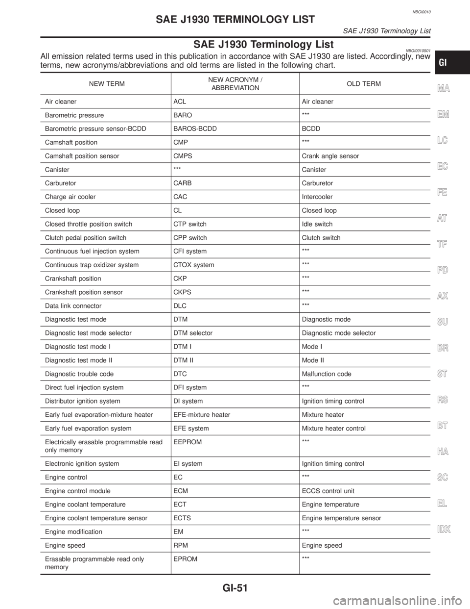
SAE J1930 Terminology ListNBGI0010S01All emission related terms used in this publication in accordance with SAE J1930 are listed. Accordingly, new
terms, new acronyms/abbreviations and old terms are listed in the following chart.
NEW TERMNEW ACRONYM /
ABBREVIATIONOLD TERM
Air cleaner ACL Air cleaner
Barometric pressure BARO ***
Barometric pressure sensor-BCDD BAROS-BCDD BCDD
Camshaft position CMP ***
Camshaft position sensor CMPS Crank angle sensor
Canister *** Canister
Carburetor CARB Carburetor
Charge air cooler CAC Intercooler
Closed loop CL Closed loop
Closed throttle position switch CTP switch Idle switch
Clutch pedal position switch CPP switch Clutch switch
Continuous fuel injection system CFI system ***
Continuous trap oxidizer system CTOX system ***
Crankshaft position CKP ***
Crankshaft position sensor CKPS ***
Data link connector DLC ***
Diagnostic test mode DTM Diagnostic mode
Diagnostic test mode selector DTM selector Diagnostic mode selector
Diagnostic test mode I DTM I Mode I
Diagnostic test mode II DTM II Mode II
Diagnostic trouble code DTC Malfunction code
Direct fuel injection system DFI system ***
Distributor ignition system DI system Ignition timing control
Early fuel evaporation-mixture heater EFE-mixture heater Mixture heater
Early fuel evaporation system EFE system Mixture heater control
Electrically erasable programmable read
only memoryEEPROM ***
Electronic ignition system EI system Ignition timing control
Engine control EC ***
Engine control module ECM ECCS control unit
Engine coolant temperature ECT Engine temperature
Engine coolant temperature sensor ECTS Engine temperature sensor
Engine modification EM ***
Engine speed RPM Engine speed
Erasable programmable read only
memoryEPROM ***MA
EM
LC
EC
FE
AT
TF
PD
AX
SU
BR
ST
RS
BT
HA
SC
EL
IDX
SAE J1930 TERMINOLOGY LIST
SAE J1930 Terminology List
GI-51
Page 1800 of 2395

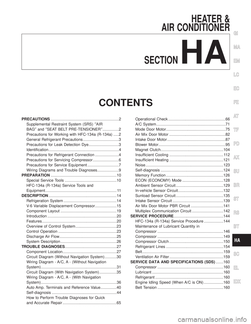
HEATER &
AIR CONDITIONER
SECTION
HA
CONTENTS
PRECAUTIONS...............................................................2
Supplemental Restraint System (SRS)²AIR
BAG²and²SEAT BELT PRE-TENSIONER²...............2
Precautions for Working with HFC-134a (R-134a) .....2
General Refrigerant Precautions .................................3
Precautions for Leak Detection Dye............................3
Identification .................................................................4
Precautions for Refrigerant Connection ......................4
Precautions for Servicing Compressor ........................6
Precautions for Service Equipment .............................7
Wiring Diagrams and Trouble Diagnoses....................9
PREPARATION.............................................................10
Special Service Tools ................................................10
HFC-134a (R-134a) Service Tools and
Equipment .................................................................. 11
DESCRIPTION...............................................................14
Refrigeration System .................................................14
V-6 Variable Displacement Compressor....................15
Component Layout ....................................................19
Introduction ................................................................20
Features .....................................................................20
Overview of Control System ......................................23
Control Operation ......................................................23
Discharge Air Flow.....................................................25
System Description ....................................................26
TROUBLE DIAGNOSES................................................27
Component Location..................................................27
Circuit Diagram (Without Navigation System) ...........30
Wiring Diagram - A/C, A - (Without Navigation
System) ......................................................................31
Circuit Diagram (With Navigation System) ................35
Wiring Diagram - A/C, A - (With Navigation
System) ......................................................................36
Auto Amp. Terminals and Reference Value...............40
Self-diagnosis ............................................................44
How to Perform Trouble Diagnoses for Quick
and Accurate Repair ..................................................65Operational Check .....................................................66
A/C System ................................................................71
Mode Door Motor.......................................................75
Air Mix Door Motor ....................................................82
Intake Door Motor ......................................................87
Blower Motor..............................................................95
Magnet Clutch..........................................................104
Insufficient Cooling .................................................. 112
Insufficient Heating ..................................................121
Noise ........................................................................123
Self-diagnosis ..........................................................124
Memory Function .....................................................126
ECON (ECONOMY) Mode ......................................128
Ambient Sensor Circuit ............................................129
In-vehicle Sensor Circuit..........................................132
Sunload Sensor Circuit ............................................135
Intake Sensor Circuit ...............................................139
Air Mix Door Motor PBR Circuit ..............................141
Multiplex Communication Circuit .............................142
SERVICE PROCEDURE..............................................144
HFC-134a (R-134a) Service Procedure ..................144
Maintenance of Lubricant Quantity in
Compressor .............................................................146
Compressor .............................................................149
Compressor Clutch ..................................................150
Refrigerant Lines .....................................................154
Belt ...........................................................................159
Ventilation Air Filter ..................................................159
SERVICE DATA AND SPECIFICATIONS (SDS).......160
Compressor .............................................................160
Lubricant ..................................................................160
Refrigerant ...............................................................160
Engine Idling Speed (When A/C is ON) ..................160
Belt Tension .............................................................160
GI
MA
EM
LC
EC
FE
AT
TF
PD
AX
SU
BR
ST
RS
BT
SC
EL
IDX
Page 1877 of 2395

Mode Door Control SpecificationNBHA0052S03
RHA135G
RHA505G
COMPONENT DESCRIPTIONNBHA0053The mode door motor is attached to the heater unit. It rotates so
that air is discharged from the outlet set by the auto amplifier. Motor
rotation is conveyed to a link which activates the mode door.
RHA488GA
DIAGNOSTIC PROCEDURE FOR MODE DOOR MOTOR
AND AIR MIX DOOR MOTOR CIRCUIT
NBHA0104SYMPTOM: Mode door motor and/or air mix door motor does
not operate normally.
TROUBLE DIAGNOSES
Mode Door Motor (Cont'd)
HA-78
Page 1880 of 2395

6 CHECK MOTOR OPERATION
Disconnect and reconnect the motor connector and confirm the motor operation.
OK or NG
OK (Return to operate
normally)©Poor contacting the motor connector
NG (Does not operate
normally)©GO TO 7.
7 CHECK MODE DOOR MOTOR OPERATION
1. Disconnect the mode door motor and air mix door motor connector.
2. Reconnect the mode door motor and confirm the motor operation.
OK or NG
OK (Mode door motor
operates normally)©Replace the air mix door motor.
NG (Mode door motor
does not operate nor-
mally)©GO TO 8.
8 CHECK AIR MIX DOOR MOTOR OPERATION
1. Disconnect the mode door motor connector.
2. Reconnect the air mix door motor and confirm the air mix door motor operation.
OK or NG
OK (Air mix door motor
operates normally)©Replace mode door motor.
NG (Air mix door motor
does not operate nor-
mally)©Replace auto amp.
RHA505G
CONTROL LINKAGE ADJUSTMENTNBHA0091Mode DoorNBHA0091S011. Install mode door motor on heater unit and connect it to main
harness.
2. Set up code No. in Self-diagnosis STEP 4. Refer to HA-45.
3. Move side link by hand and hold mode door in DEF mode.
4. Attach mode door motor rod to side link rod holder.
5. Make sure mode door operates properly when changing from
code No.
toby pushing DEF switch.
VENT B/L B/L FOOT D/F DEF
GI
MA
EM
LC
EC
FE
AT
TF
PD
AX
SU
BR
ST
RS
BT
SC
EL
IDX
TROUBLE DIAGNOSES
Mode Door Motor (Cont'd)
HA-81
Page 1884 of 2395

Air Mix Door Control SpecificationNBHA0059S03
RHA137G
RHA849E
COMPONENT DESCRIPTIONNBHA0060The air mix door motor is attached to the heater unit. It rotates so
that the air mix door is opened or closed to a position set by the
auto amplifier. Motor rotation is then conveyed through a shaft and
the air mix door position is then fed back to the auto amplifier by
PBR built-in air mix door motor.
RHA504G
SHA522EA
CONTROL LINKAGE ADJUSTMENTNBHA0099Air Mix Door (Water Cock)NBHA0099S011. Install air mix door motor on heater unit and connect it to main
harness.
2. Set up code No. 41 in Self-diagnosis STEP 4. Refer to HA-44.
3. Move air mix door lever by hand and hold it in full cold posi-
tion.
4. Attach air mix door lever to rod holder.
5. Make sure air mix door operates properly when changing from
code No.
toby pushing DEF switch.
Full cold Full hot
6. Set up code No.in Self-diagnosis STEP 4.
7. Attach water cock rod to air mix door lever and secure with clip.
8. Rotate air mix door lever (CLOCKWISE completely) and hold
water cock rod and link lever in the full cold position.
9. Attach water cock rod to link lever and secure with clip (white
mark on cable housing should be centered under the retaining
clip).
GI
MA
EM
LC
EC
FE
AT
TF
PD
AX
SU
BR
ST
RS
BT
SC
EL
IDX
TROUBLE DIAGNOSES
Air Mix Door Motor (Cont'd)
HA-85
Page 1931 of 2395

Temperature ÉC (ÉF) Resistance kW
35 (95) 1.51
40 (104) 1.27
45 (113) 1.07
If NG, replace ambient sensor.
RHA103G
In-vehicle Sensor Circuit
COMPONENT DESCRIPTIONNBHA0043In-vehicle sensorNBHA0043S01The in-vehicle sensor is located on instrument lower panel. It con-
verts variations in temperature of compartment air drawn from the
aspirator into a resistance value. It is then input into the auto
amplifier.
RHA636F
RHA482A
AspiratorNBHA0043S02The aspirator is located in front of heater unit. It produces vacuum
pressure due to air discharged from the heater unit, continuously
taking compartment air in the aspirator.
RHA056GH
DIAGNOSTIC PROCEDURENBHA0044SYMPTOM: In-vehicle sensor circuit is open or shorted. (or
þ
is indicated on the display as a result of conducting Self-
diagnosis STEP 2.)
TROUBLE DIAGNOSES
Ambient Sensor Circuit (Cont'd)
HA-132
Page 1957 of 2395

5. If a leak detector detects a leak, verify at least once by blow-
ing compressed air into area of suspected leak, then repeat
check as outlined above.
6. Do not stop when one leak is found. Continue to check for
additional leaks at all system components.
If no leaks are found, perform steps7-10.
7. Start engine.
8. Set the heater A/C control as follows:
1) A/C switch ON.
2) Face mode
3) Recirculation switch ON
4) Max cold temperature
5) Fan speed high
9. Run engine at 1,500 rpm for at least 2 minutes.
10. Turn engine off and perform leak check again following steps
4 through 6 above.
SHA839E
Refrigerant leaks should be checked immediately after
stopping the engine. Begin with the leak detector at the
compressor. The pressure on the high pressure side will
gradually drop after refrigerant circulation stops and pres-
sure on the low pressure side will gradually rise, as shown
in the graph. Some leaks are more easily detected when
pressure is high.
11. Before connecting ACR4 to vehicle, check ACR4 gauges. No
refrigerant pressure should be displayed. If pressure is
displayed, recover refrigerant from equipment lines and then
check refrigerant purity.
12. Confirm refrigerant purity in supply tank using ACR4 and refrig-
erant identifier.
13. Confirm refrigerant purity in vehicle A/C system using ACR4
and refrigerant identifier.
14. Discharge A/C system using approved refrigerant recovery
equipment. Repair the leaking fitting or component as neces-
sary.
15. Evacuate and recharge A/C system and perform the leak test
to confirm no refrigerant leaks.
16. Conduct A/C performance test to ensure system works
properly.
SERVICE PROCEDURE
Refrigerant Lines (Cont'd)
HA-158
Page 1963 of 2395

E
ECM input/output signal ...............................EC-127
ECTS - Wiring diagram ........................EC-171, 189
Electric sun roof ............................................EL-173
Electrical diagnoses.........................................GI-24
Electrical ignition system ................................EC-30
Electrical unit ................................................Foldout
Electrical units location .................................EL-436
Engine compartment .......................................BT-58
Engine control circuit diagram........................EC-24
Engine control component parts
location .......................................................EC-20
Engine control module (ECM) ......................EC-444
Engine control system diagram and
chart ............................................................EC-25
Engine coolant temperature sensor
(ECTS) ..............................................EC-169, 187
Engine fail-safe system ................................EC-117
Engine oil filter replacement ..........................MA-18
Engine oil precautions .......................................GI-8
Engine oil replacement ..................................MA-18
Engine outer component parts ......................EM-10
Engine removal ..............................................EM-57
Engine room - See Engine
compartment................................................BT-58
Engine serial number ......................................GI-43
EVAP canister.................................................EC-33
EVAP canister purge volume control
solenoid valve.............................EC-32, 367, 541
EVAP canister vent control
valve .........................................EC-374, 553, 573
EVAP control system (small leak)
diagnosis ..................................EC-352, 394, 526
EVAP control system pressure sensor.........EC-381
EVAP control system purge flow moni-
toring diagnosis.........................................EC-561
EVAP vapor lines inspection ..........................MA-20
Evaporative emission (EVAP) system ............EC-32
Exhaust system ................................................FE-8
Exhaust system inspection ............................MA-21
Exterior ............................................................BT-35
F
4LO indicator lamp........................................TF-104
4WD shift indicator lamp.................................TF-98
4WD shift switch ............................................TF-111
4WD solenoid valve.......................................TF-111
4WD warning lamp .........................................TF-13
Fan control amp. ............................................HA-98
F/FOG - Wiring diagram .................................EL-72
Final drive disassembly ..................................PD-43
Final drive pre-inspection ...............................PD-43
Final drive removal and installation ...............PD-43
Finisher, interior - See Trim ............................BT-28
F/LID - Wiring diagram .................................EL-180
Fluid temperature sensor (A/T) .....................AT-110Fluids ..............................................................MA-11
Flywheel runout..............................................EM-70
FO2H-L - Wiring diagram .............................EC-243
FO2H-R - Wiring diagram ............................EC-242
Fog lamp, front................................................EL-70
Fog lamp, front, removal and
installation ...................................................BT-12
Forward clutch ...............................................AT-320
F/PUMP - Wiring diagram ............................EC-627
Freeze frame data ..........................................EC-60
FRO2LH - Wiring diagram ...........EC-197, 223, 235
FRO2RH - Wiring diagram...........EC-196, 222, 234
Front axle..........................................................AX-2
Front bumper ..................................................BT-12
Front case (Transfer) ....................................TF-133
Front combination lamp removal and
installation ...................................................BT-12
Front disc brake .............................................BR-22
Front door .......................................................BT-18
Front drive shaft (Transfer) ...........................TF-125
Front final drive disassembly (4WD) ..............PD-18
Front final drive pre-inspection (4WD) ...........PD-18
Front final drive removal and installa-
tion (4WD)...................................................PD-18
Front fog lamp.................................................EL-70
Front fog lamp removal and installation .........BT-12
Front heated oxygen sensor (HO2S)
(Left bank) ................EC-192, 202, 210, 218, 231
Front heated oxygen sensor (HO2S)
(Right bank) .............EC-192, 202, 210, 218, 231
Front heated oxygen sensor heater
(Left bank).................................................EC-240
Front heated oxygen sensor heater
(Right bank) ..............................................EC-240
Front revolution sensor (Transfer) ................TF-112
Front seat ........................................................BT-41
Front seat belt ..................................................RS-4
Front suspension ..............................................SU-2
Front washer .................................................EL-136
Front wiper ....................................................EL-136
Fuel cut control (at no load & high
engine speed) .............................................EC-32
Fuel filler lid.....................................................BT-15
Fuel filter replacement ...................................MA-16
Fuel gauge ......................................................EL-94
Fuel injection system (Left bank) .........EC-294, 302
Fuel injection system (Right bank) ......EC-294, 302
Fuel lid opener, electric.................................EL-180
Fuel line inspection ........................................MA-16
Fuel precautions ................................................GI-8
Fuel pressure check .......................................EC-39
Fuel pressure regulator ..................................EC-40
Fuel pressure release ....................................EC-39
Fuel pump ....................................................EC-625
Fuel system ......................................................FE-4
Fuel tank temperature sensor ......................EC-309
Fuel tank vacuum relief valve ........................EC-33
FUELLH - Wiring diagram....................EC-297, 305
FUELRH - Wiring diagram ...................EC-296, 304
Fuse ................................................................EL-16
Fuse block ....................................................Foldout
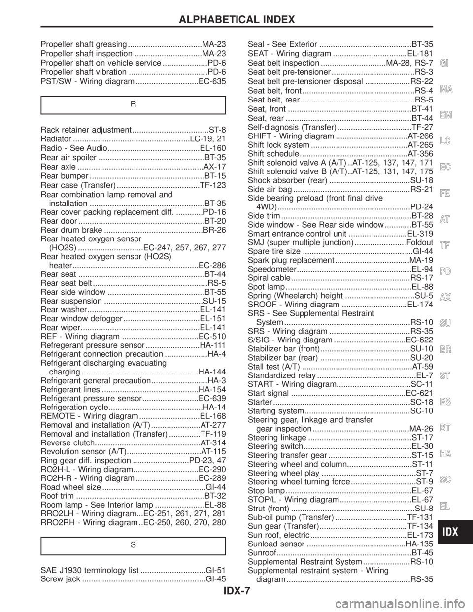
ALPHABETICAL INDEX
IDX-4
Page 1966 of 2395

Propeller shaft greasing .................................MA-23
Propeller shaft inspection ..............................MA-23
Propeller shaft on vehicle service ....................PD-6
Propeller shaft vibration ...................................PD-6
PST/SW - Wiring diagram ............................EC-635
R
Rack retainer adjustment ..................................ST-8
Radiator ....................................................LC-19, 21
Radio - See Audio.........................................EL-160
Rear air spoiler ...............................................BT-35
Rear axle ........................................................AX-17
Rear bumper ...................................................BT-15
Rear case (Transfer) .....................................TF-123
Rear combination lamp removal and
installation ...................................................BT-35
Rear cover packing replacement diff. ............PD-16
Rear door ........................................................BT-20
Rear drum brake ............................................BR-26
Rear heated oxygen sensor
(HO2S) .............................EC-247, 257, 267, 277
Rear heated oxygen sensor (HO2S)
heater ........................................................EC-286
Rear seat ........................................................BT-44
Rear seat belt ...................................................RS-5
Rear side window ...........................................BT-55
Rear suspension ............................................SU-15
Rear washer..................................................EL-141
Rear window defogger ..................................EL-151
Rear wiper.....................................................EL-141
REF - Wiring diagram ..................................EC-510
Refregerant pressure sensor ........................HA-111
Refrigerant connection precaution ...................HA-4
Refrigerant discharging evacuating
charging ....................................................HA-144
Refrigerant general precaution.........................HA-3
Refrigerant lines ...........................................HA-154
Refrigerant pressure sensor.........................EC-639
Refrigeration cycle..........................................HA-14
REMOTE - Wiring diagram ...........................EL-168
Removal and installation (A/T) ......................AT-277
Removal and installation (Transfer) ..............TF-119
Reverse clutch...............................................AT-314
Revolution sensor (A/T).................................AT-115
Ring gear diff. inspection .........................PD-23, 47
RO2H-L - Wiring diagram.............................EC-290
RO2H-R - Wiring diagram ............................EC-289
Road wheel size ..............................................GI-44
Roof trim .........................................................BT-32
Room lamp - See Interior lamp ......................EL-88
RRO2LH - Wiring diagram...EC-251, 261, 271, 281
RRO2RH - Wiring diagram ..EC-250, 260, 270, 280
S
SAE J1930 terminology list .............................GI-51
Screw jack .......................................................GI-45Seal - See Exterior .........................................BT-35
SEAT - Wiring diagram .................................EL-181
Seat belt inspection .............................MA-28, RS-7
Seat belt pre-tensioner .....................................RS-3
Seat belt pre-tensioner disposal ....................RS-22
Seat belt, front ..................................................RS-4
Seat belt, rear...................................................RS-5
Seat, front .......................................................BT-41
Seat, rear ........................................................BT-44
Self-diagnosis (Transfer) .................................TF-27
SHIFT - Wiring diagram ................................AT-266
Shift lock system ...........................................AT-265
Shift schedule ................................................AT-356
Shift solenoid valve A (A/T) ..AT-125, 137, 147, 171
Shift solenoid valve B (A/T) ..AT-125, 131, 147, 175
Shock absorber (rear) ....................................SU-18
Side air bag ....................................................RS-21
Side bearing preload (front final drive
4WD) ...........................................................PD-24
Side trim ..........................................................BT-28
Side window - See Rear side window ............BT-55
Smart entrance control unit ..........................EL-319
SMJ (super multiple junction) .......................Foldout
Spare tire size .................................................GI-44
Spark plug replacement .................................MA-19
Speedometer...................................................EL-94
Spiral cable.....................................................RS-17
Spot lamp ........................................................EL-88
Spring (Wheelarch) height ...............................SU-5
SROOF - Wiring diagram .............................EL-174
SRS - See Supplemental Restraint
System ........................................................RS-10
SRS - Wiring diagram ....................................RS-35
S/SIG - Wiring diagram ................................EC-622
Stabilizer bar (front)........................................SU-10
Stabilizer bar (rear) ........................................SU-20
Stall test (A/T) .................................................AT-59
Standardized relay ............................................EL-7
START - Wiring diagram.................................SC-11
Start signal ...................................................EC-621
Starter .............................................................SC-18
Starting system...............................................SC-10
Steering gear, linkage and transfer
gear inspection ...........................................MA-26
Steering linkage ..............................................ST-17
Steering switch................................................EL-30
Steering transfer gear .....................................ST-15
Steering wheel and column.............................ST-11
Steering wheel play ..........................................ST-7
Steering wheel turning force .............................ST-9
Stop lamp ........................................................EL-67
STOP/L - Wiring diagram................................EL-67
Strut (front) .......................................................SU-8
Sub-oil pump (Transfer) ................................TF-131
Sun gear (Transfer).......................................TF-134
Sun roof, electric ...........................................EL-173
Sunload sensor ............................................HA-135
Sunroof............................................................BT-45
Supplemental Restraint System .....................RS-10
Supplemental restraint system - Wiring
diagram .......................................................RS-35
GI
MA
EM
LC
EC
FE
AT
TF
PD
AX
SU
BR
ST
RS
BT
HA
SC
EL
ALPHABETICAL INDEX
IDX-7
Page 1999 of 2395

NBMA0003
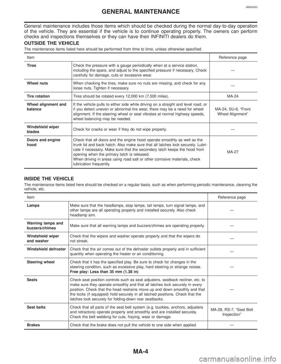
General maintenance includes those items which should be checked during the normal day-to-day operation
of the vehicle. They are essential if the vehicle is to continue operating properly. The owners can perform
checks and inspections themselves or they can have their INFINITI dealers do them.
OUTSIDE THE VEHICLE
The maintenance items listed here should be performed from time to time, unless otherwise specified.
ItemReference page
TiresCheck the pressure with a gauge periodically when at a service station,
including the spare, and adjust to the specified pressure if necessary. Check
carefully for damage, cuts or excessive wear.Ð
Wheel nutsWhen checking the tires, make sure no nuts are missing, and check for any
loose nuts. Tighten if necessary.Ð
Tire rotationTires should be rotated every 12,000 km (7,500 miles). MA-24
Wheel alignment and
balanceIf the vehicle pulls to either side while driving on a straight and level road, or
if you detect uneven or abnormal tire wear, there may be a need for wheel
alignment. If the steering wheel or seat vibrates at normal highway speeds,
wheel balancing may be needed.MA-24, SU-6, ªFront
Wheel Alignmentº
Windshield wiper
bladesCheck for cracks or wear if they do not wipe properly. Ð
Doors and engine
hoodCheck that all doors and the engine hood operate smoothly as well as the
trunk lid and back hatch. Also make sure that all latches lock securely. Lubri-
cate if necessary. Make sure that the secondary latch keeps the hood from
opening when the primary latch is released.
When driving in areas using road salt or other corrosive materials, check
lubrication frequently.MA-27
INSIDE THE VEHICLE
The maintenance items listed here should be checked on a regular basis, such as when performing periodic maintenance, cleaning the
vehicle, etc.
ItemReference page
LampsMake sure that the headlamps, stop lamps, tail lamps, turn signal lamps, and
other lamps are all operating properly and installed securely. Also check
headlamp aim.Ð
Warning lamps and
buzzers/chimesMake sure that all warning lamps and buzzers/chimes are operating properly. Ð
Windshield wiper
and washerCheck that the wipers and washer operate properly and that the wipers do
not streak.Ð
Windshield defrosterCheck that the air comes out of the defroster outlets properly and in sufficient
quantity when operating the heater or air conditioning.Ð
Steering wheelCheck that it has the specified play. Be sure to check for changes in the
steering condition, such as excessive play, hard steering or strange noises.
Free play: Less than 35 mm (1.38 in)Ð
SeatsCheck seat position controls such as seat adjusters, seatback recliner, etc. to
make sure they operate smoothly and that all latches lock securely in every
position. Check that the head restrains move up and down smoothly and that
the locks (if equipped) hold securely in all latched positions. Check that the
latches lock securely for folding-down rear seatbacks.Ð
Seat beltsCheck that all parts of the seat belt system (e.g. buckles, anchors, adjusters
and retractors) operate properly and smoothly and are installed securely.
Check the belt webbing for cuts, fraying, wear or damage.MA-28, RS-7, ªSeat Belt
Inspectionº
BrakesCheck that the brake does not pull the vehicle to one side when applied. Ð
GENERAL MAINTENANCE
MA-4