torque INFINITI QX4 2001 Factory Workshop Manual
[x] Cancel search | Manufacturer: INFINITI, Model Year: 2001, Model line: QX4, Model: INFINITI QX4 2001Pages: 2395, PDF Size: 43.2 MB
Page 234 of 2395

6 DETECT MALFUNCTIONING ITEM
1. Remove control valve assembly. Refer to ªON-VEHICLE SERVICEº, AT-273.
2. Check the following items:
IValves to control line pressure (Pressure regulator valve, pressure modifier valve, pilot valve and pilot filter)
ILine pressure solenoid valve
3. Disassemble A/T.
4. Check the following items:
IOil pump assembly
ITorque converter
IReverse clutch assembly
IHigh clutch assembly
ILow & reverse brake assembly
ILow one-way clutch
©Repair or replace damaged parts.GI
MA
EM
LC
EC
FE
TF
PD
AX
SU
BR
ST
RS
BT
HA
SC
EL
IDX
TROUBLE DIAGNOSES FOR SYMPTOMS
6. Vehicle Does Not Creep Backward In ªRº Position (Cont'd)
AT-229
Page 237 of 2395

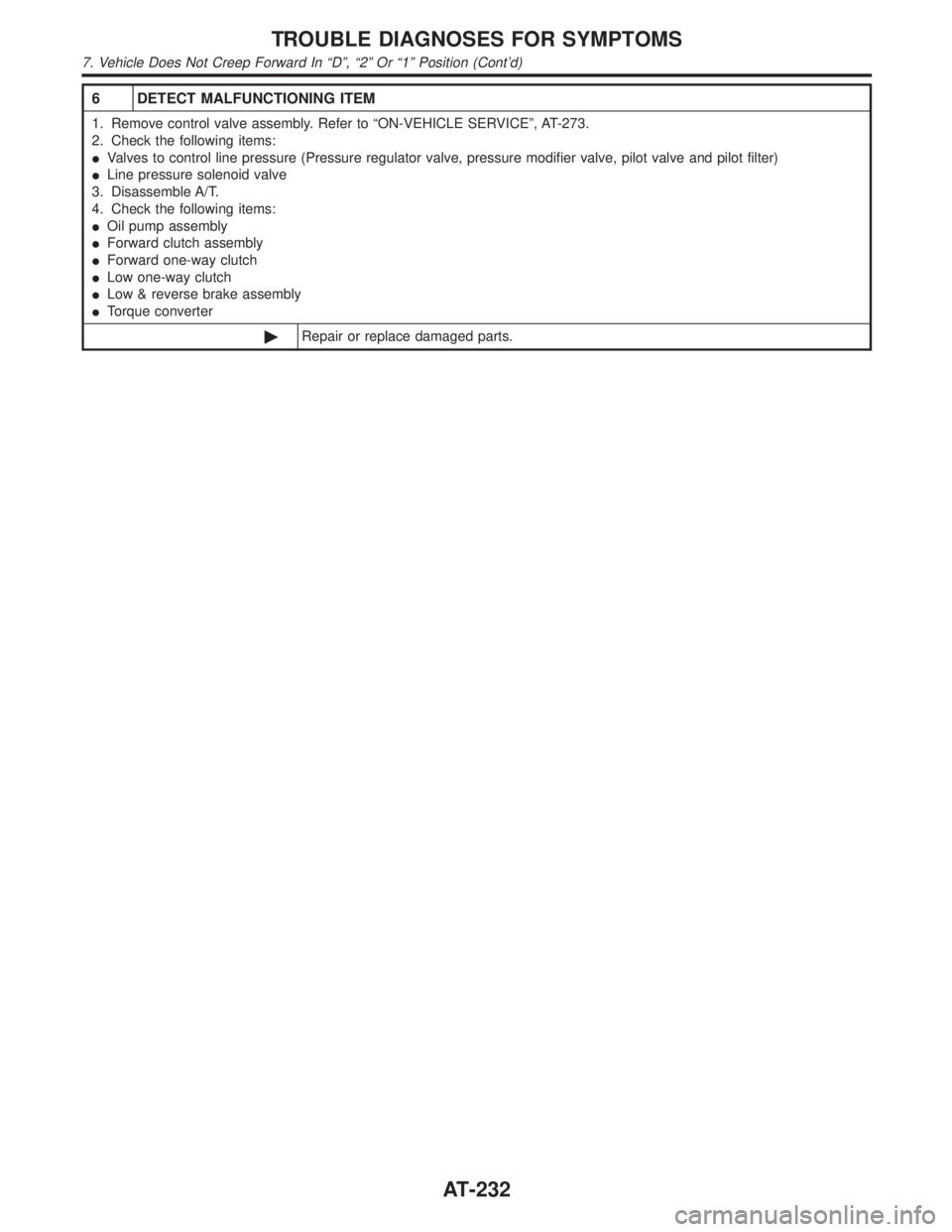
6 DETECT MALFUNCTIONING ITEM
1. Remove control valve assembly. Refer to ªON-VEHICLE SERVICEº, AT-273.
2. Check the following items:
IValves to control line pressure (Pressure regulator valve, pressure modifier valve, pilot valve and pilot filter)
ILine pressure solenoid valve
3. Disassemble A/T.
4. Check the following items:
IOil pump assembly
IForward clutch assembly
IForward one-way clutch
ILow one-way clutch
ILow & reverse brake assembly
ITorque converter
©Repair or replace damaged parts.
TROUBLE DIAGNOSES FOR SYMPTOMS
7. Vehicle Does Not Creep Forward In ªDº, ª2º Or ª1º Position (Cont'd)
AT-232
Page 240 of 2395

7 CHECK SYMPTOM
Check again.
OK or NG
OK©INSPECTION END
NG©1. Perform TCM input/output signal inspection.
2. If NG, recheck TCM pin terminals for damage or loose connection with harness con-
nector.
8 DETECT MALFUNCTIONING ITEM
1. Remove control valve assembly.
Refer to AT-273.
2. Check the following items:
IShift valve A
IShift valve B
IShift solenoid valve A
IShift solenoid valve B
IPilot valve
IPilot filter
3. Disassemble A/T.
4. Check the following items:
IForward clutch assembly
IForward one-way clutch
ILow one-way clutch
IHigh clutch assembly
ITorque converter
IOil pump assembly
OK or NG
OK©GO TO 7.
NG©Repair or replace damaged parts.
GI
MA
EM
LC
EC
FE
TF
PD
AX
SU
BR
ST
RS
BT
HA
SC
EL
IDX
TROUBLE DIAGNOSES FOR SYMPTOMS
8. Vehicle Cannot Be Started From D1(Cont'd)
AT-235
Page 249 of 2395

6 CHECK SYMPTOM
Check again.
OK or NG
OK©INSPECTION END
NG©1. Perform TCM input/output signal inspection.
2. If NG, recheck TCM pin terminals for damage or loose connection with harness con-
nector.
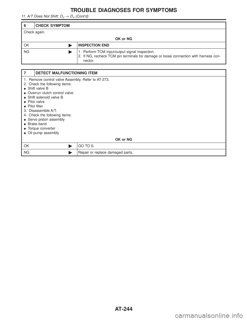
7 DETECT MALFUNCTIONING ITEM
1. Remove control valve Assembly. Refer to AT-273.
2. Check the following items:
IShift valve B
IOverrun clutch control valve
IShift solenoid valve B
IPilot valve
IPilot filter
3. Disassemble A/T.
4. Check the following items:
IServo piston assembly
IBrake band
ITorque converter
IOil pump assembly
OK or NG
OK©GO TO 6.
NG©Repair or replace damaged parts.
TROUBLE DIAGNOSES FOR SYMPTOMS
11. A/T Does Not Shift: D3®D4(Cont'd)
AT-244
Page 250 of 2395

12. A/T Does Not Perform Lock-up=NBAT0084SYMPTOM:
A/T does not perform lock-up at the specified speed.
1 CHECK SELF-DIAGNOSTIC RESULTS
Does self-diagnosis show damage to torque converter clutch solenoid valve circuit after cruise test?
SAT581I
YesorNo
Ye s©Check torque converter clutch solenoid valve circuit. Refer to ªDTC P0740º, AT-148.
No©GO TO 2.
2 CHECK THROTTLE POSITION SENSOR
Check throttle position sensor. Refer to EC-174, ªDescriptionº.
SAT142K
OK or NG
OK©GO TO 3.
NG©Repair or replace throttle position sensor.
3 DETECT MALFUNCTIONING ITEM
1. Remove control valve. Refer to AT-273.
2. Check following items:
ITorque converter clutch control valve
ITorque converter relief valve
ITorque converter clutch solenoid valve
IPilot valve
IPilot filter
OK or NG
OK©GO TO 4.
NG©Repair or replace damaged parts.
GI
MA
EM
LC
EC
FE
TF
PD
AX
SU
BR
ST
RS
BT
HA
SC
EL
IDX
TROUBLE DIAGNOSES FOR SYMPTOMS
12. A/T Does Not Perform Lock-up
AT-245
Page 252 of 2395

13. A/T Does Not Hold Lock-up Condition=NBAT0085SYMPTOM:
A/T does not hold lock-up condition for more than 30 seconds.
1 CHECK DIAGNOSTIC RESULTS
Does self-diagnosis show damage to engine speed signal circuit after cruise test?
SAT582I
YesorNo
Ye s©Check engine speed signal circuit. Refer to ªDTC P0725º, AT-116.
No©GO TO 2.
2 CHECK A/T FLUID CONDITION
1. Remove oil pan.
2. Check A/T fluid condition.
SAT171B
OK or NG
OK©GO TO 3.
NG©GO TO 5.
3 DETECT MALFUNCTIONING ITEM
1. Remove control valve assembly. Refer to AT-273.
2. Check the following items:
ITorque converter clutch control valve
IPilot valve
IPilot filter
OK or NG
OK©GO TO 4.
NG©Repair or replace damaged parts.
GI
MA
EM
LC
EC
FE
TF
PD
AX
SU
BR
ST
RS
BT
HA
SC
EL
IDX
TROUBLE DIAGNOSES FOR SYMPTOMS
13. A/T Does Not Hold Lock-up Condition
AT-247
Page 253 of 2395

4 CHECK SYMPTOM
Check again.
OK or NG
OK©INSPECTION END
NG©1. Perform TCM input/output signal inspection.
2. If NG, recheck TCM pin terminals for damage or loose connection with harness con-
nector.
5 DETECT MALFUNCTIONING ITEM
1. Remove control valve assembly. Refer to AT-273.
2. Check the following items:
ITorque converter clutch control valve
IPilot valve
IPilot filter
3. Disassemble A/T.
4. Check torque converter and oil pump assembly.
OK or NG
OK©GO TO 4.
NG©Repair or replace damaged parts.
TROUBLE DIAGNOSES FOR SYMPTOMS
13. A/T Does Not Hold Lock-up Condition (Cont'd)
AT-248
Page 279 of 2395

SAT360IA
Revolution Sensor ReplacementNBAT0210Ð 4WD MODEL ÐNBAT0210S011. Remove rear engine mounting member from side member
while supporting A/T with transfer case with jack. Tighten rear
engine mounting member to the specified torque. Refer to
EM-59, ªRear Engine Mountingº.
2. Lower A/T with transfer case as much as possible.
3. Remove revolution sensor from A/T.
4. Reinstall any part removed.
IAlways use new sealing parts.
SAT661I
Ð 2WD MODEL ÐNBAT0210S02IRemove revolution sensor from A/T.
IAlways use new sealing parts.
SAT136K
Turbine Revolution Sensor ReplacementNBAT02311. Remove A/T assembly, Refer to ªRemovalº, AT-277.
2. Remove turbine revolution sensor from A/T assembly upper
side.
3. Reinstall any part removed.
IAlways use new sealing parts.
SAT035E
Rear Oil Seal ReplacementNBAT0211Ð 4WD MODEL ÐNBAT0211S011. Remove transfer case from vehicle. Refer to TF-119, ªRemovalº.
2. Remove rear oil seal.
IDo not remove oil seal unless it is to be replaced.
3. Install rear oil seal.
IApply ATF before installing.
4. Reinstall any part removed.
ON-VEHICLE SERVICE
Revolution Sensor Replacement
AT-274
Page 280 of 2395

SAT544J
SAT546J
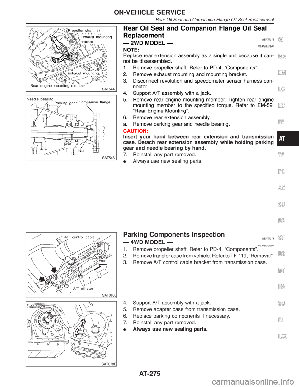
Rear Oil Seal and Companion Flange Oil Seal
Replacement
NBAT0212Ð 2WD MODEL ÐNBAT0212S01NOTE:
Replace rear extension assembly as a single unit because it can-
not be disassembled.
1. Remove propeller shaft. Refer to PD-4, ªComponentsº.
2. Remove exhaust mounting and mounting bracket.
3. Disconnect revolution and speedometer sensor harness con-
nector.
4. Support A/T assembly with a jack.
5. Remove rear engine mounting member. Tighten rear engine
mounting member to the specified torque. Refer to EM-59,
ªRear Engine Mountingº.
6. Remove rear extension assembly.
a. Remove parking gear and needle bearing.
CAUTION:
Insert your hand between rear extension and transmission
case. Detach rear extension assembly while holding parking
gear and needle bearing by hand.
7. Reinstall any part removed.
IAlways use new sealing parts.
SAT083J
Parking Components InspectionNBAT0213Ð 4WD MODEL ÐNBAT0213S011. Remove propeller shaft. Refer to PD-4, ªComponentsº.
2. Remove transfer case from vehicle. Refer to TF-119, ªRemovalº.
3. Remove A/T control cable bracket from transmission case.
SAT078B
4. Support A/T assembly with a jack.
5. Remove adapter case from transmission case.
6. Replace parking components if necessary.
7. Reinstall any part removed.
IAlways use new sealing parts.
GI
MA
EM
LC
EC
FE
TF
PD
AX
SU
BR
ST
RS
BT
HA
SC
EL
IDX
ON-VEHICLE SERVICE
Rear Oil Seal and Companion Flange Oil Seal Replacement
AT-275
Page 281 of 2395

SAT551J
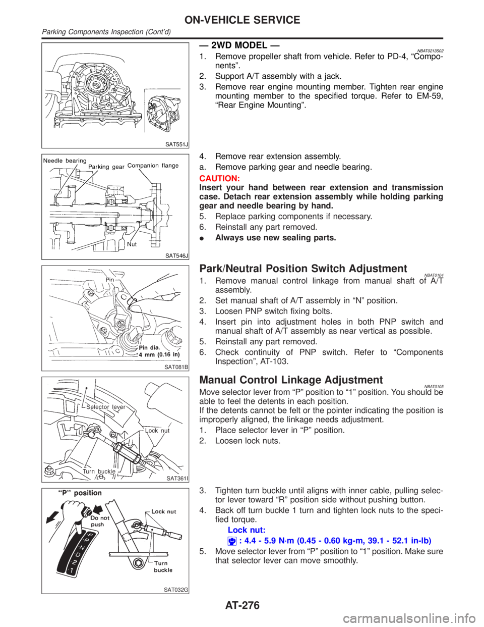
Ð 2WD MODEL ÐNBAT0213S021. Remove propeller shaft from vehicle. Refer to PD-4, ªCompo-
nentsº.
2. Support A/T assembly with a jack.
3. Remove rear engine mounting member. Tighten rear engine
mounting member to the specified torque. Refer to EM-59,
ªRear Engine Mountingº.
SAT546J
4. Remove rear extension assembly.
a. Remove parking gear and needle bearing.
CAUTION:
Insert your hand between rear extension and transmission
case. Detach rear extension assembly while holding parking
gear and needle bearing by hand.
5. Replace parking components if necessary.
6. Reinstall any part removed.
IAlways use new sealing parts.
SAT081B
Park/Neutral Position Switch AdjustmentNBAT01041. Remove manual control linkage from manual shaft of A/T
assembly.
2. Set manual shaft of A/T assembly in ªNº position.
3. Loosen PNP switch fixing bolts.
4. Insert pin into adjustment holes in both PNP switch and
manual shaft of A/T assembly as near vertical as possible.
5. Reinstall any part removed.
6. Check continuity of PNP switch. Refer to ªComponents
Inspectionº, AT-103.
SAT361I
Manual Control Linkage AdjustmentNBAT0105Move selector lever from ªPº position to ª1º position. You should be
able to feel the detents in each position.
If the detents cannot be felt or the pointer indicating the position is
improperly aligned, the linkage needs adjustment.
1. Place selector lever in ªPº position.
2. Loosen lock nuts.
SAT032G
3. Tighten turn buckle until aligns with inner cable, pulling selec-
tor lever toward ªRº position side without pushing button.
4. Back off turn buckle 1 turn and tighten lock nuts to the speci-
fied torque.
Lock nut:
: 4.4 - 5.9 N´m (0.45 - 0.60 kg-m, 39.1 - 52.1 in-lb)
5. Move selector lever from ªPº position to ª1º position. Make sure
that selector lever can move smoothly.
ON-VEHICLE SERVICE
Parking Components Inspection (Cont'd)
AT-276