dead battery INFINITI QX4 2001 Factory Service Manual
[x] Cancel search | Manufacturer: INFINITI, Model Year: 2001, Model line: QX4, Model: INFINITI QX4 2001Pages: 2395, PDF Size: 43.2 MB
Page 653 of 2395

Symptom Matrix ChartNBEC0041SYSTEM Ð BASIC ENGINE CONTROL SYSTEMNBEC0041S01
SYMPTOM
Reference
page
HARD/NO START/RESTART (EXCP. HA)
ENGINE STALL
HESITATION/SURGING/FLAT SPOT
SPARK KNOCK/DETONATION
LACK OF POWER/POOR ACCELERATION
HIGH IDLE/LOW IDLE
ROUGH IDLE/HUNTING
IDLING VIBRATION
SLOW/NO RETURN TO IDLE
OVERHEATS/WATER TEMPERATURE HIGH
EXCESSIVE FUEL CONSUMPTION
EXCESSIVE OIL CONSUMPTION
BATTERY DEAD (UNDER CHARGE)
Warranty symptom code AA AB AC AD AE AF AG AH AJ AK AL AM HA
Fuel Fuel pump circuit11232 2 2 3 2EC-625
Fuel pressure regulator system3344444 4 4 4EC-40
Injector circuit11232 2 2 2EC-616
Evaporative emission system
3344444 4 4 4EC-32
Air Positive crankcase ventilation sys-
tem1 EC-38
Incorrect idle speed adjustment 1 1 1 1 1 EC-101
IACV-AAC valve circuit1123322 2 2 2 2EC-422
Ignition Incorrect ignition timing adjustment33111 1 1 1EC-101
Ignition circuit 1 1 2 2 2 2 2 2 EC-499
Main power supply and ground circuit
22333 3 32
3EC-142
Air conditioner circuit 3 3 2 HA section
1 - 6: The numbers refer to the order of inspection.
(continued on next page)
TROUBLE DIAGNOSIS Ð GENERAL DESCRIPTION
Symptom Matrix Chart
EC-118
Page 654 of 2395
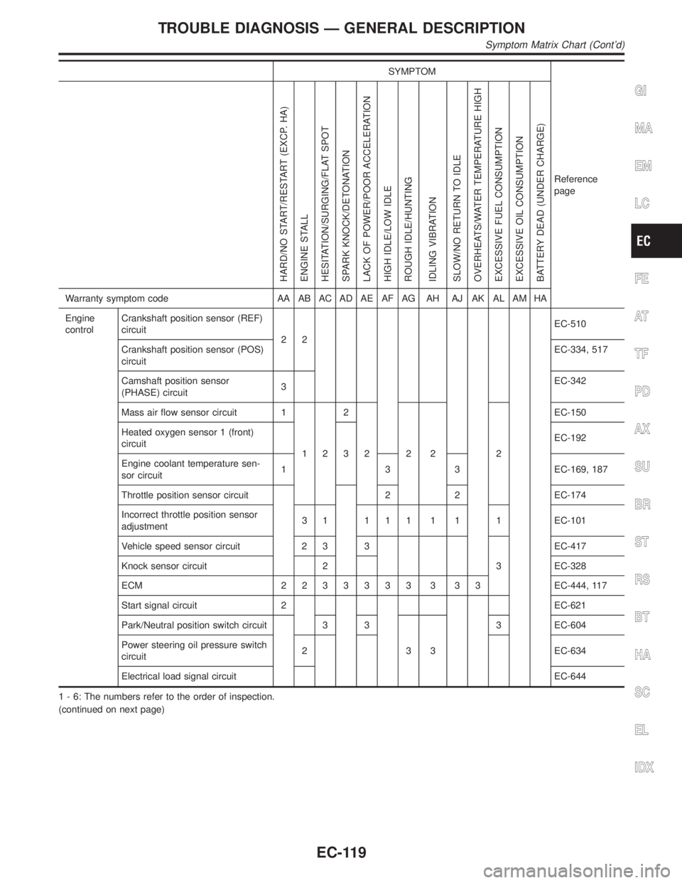
SYMPTOM
Reference
page
HARD/NO START/RESTART (EXCP. HA)
ENGINE STALL
HESITATION/SURGING/FLAT SPOT
SPARK KNOCK/DETONATION
LACK OF POWER/POOR ACCELERATION
HIGH IDLE/LOW IDLE
ROUGH IDLE/HUNTING
IDLING VIBRATION
SLOW/NO RETURN TO IDLE
OVERHEATS/WATER TEMPERATURE HIGH
EXCESSIVE FUEL CONSUMPTION
EXCESSIVE OIL CONSUMPTION
BATTERY DEAD (UNDER CHARGE)
Warranty symptom code AA AB AC AD AE AF AG AH AJ AK AL AM HA
Engine
controlCrankshaft position sensor (REF)
circuit
22EC-510
Crankshaft position sensor (POS)
circuitEC-334, 517
Camshaft position sensor
(PHASE) circuit3EC-342
Mass air flow sensor circuit 1
122
222 2EC-150
Heated oxygen sensor 1 (front)
circuit
3EC-192
Engine coolant temperature sen-
sor circuit1 3 3 EC-169, 187
Throttle position sensor circuit 2 2 EC-174
Incorrect throttle position sensor
adjustment3 1 1 1 1 1 1 1 EC-101
Vehicle speed sensor circuit 2 3 3
3EC-417
Knock sensor circuit 2 EC-328
ECM 2233333 3 33EC-444, 117
Start signal circuit 2 EC-621
Park/Neutral position switch circuit 3 3
333 EC-604
Power steering oil pressure switch
circuit2 EC-634
Electrical load signal circuitEC-644
1 - 6: The numbers refer to the order of inspection.
(continued on next page)
GI
MA
EM
LC
FE
AT
TF
PD
AX
SU
BR
ST
RS
BT
HA
SC
EL
IDX
TROUBLE DIAGNOSIS Ð GENERAL DESCRIPTION
Symptom Matrix Chart (Cont'd)
EC-119
Page 655 of 2395
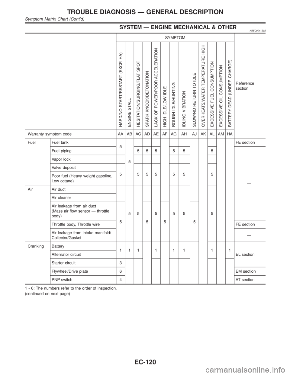
SYSTEM Ð ENGINE MECHANICAL & OTHERNBEC0041S02
SYMPTOM
Reference
section
HARD/NO START/RESTART (EXCP. HA)
ENGINE STALL
HESITATION/SURGING/FLAT SPOT
SPARK KNOCK/DETONATION
LACK OF POWER/POOR ACCELERATION
HIGH IDLE/LOW IDLE
ROUGH IDLE/HUNTING
IDLING VIBRATION
SLOW/NO RETURN TO IDLE
OVERHEATS/WATER TEMPERATURE HIGH
EXCESSIVE FUEL CONSUMPTION
EXCESSIVE OIL CONSUMPTION
BATTERY DEAD (UNDER CHARGE)
Warranty symptom code AA AB AC AD AE AF AG AH AJ AK AL AM HA
Fuel Fuel tank
5
5FE section
Fuel piping 5 5 5 5 5 5
Ð Vapor lock
Valve deposit
5 555 5 5 5
Poor fuel (Heavy weight gasoline,
Low octane)
Air Air duct
55555 5 Air cleaner
Air leakage from air duct
(Mass air flow sensor Ð throttle
body)
555 5
Throttle body, Throttle wireFE section
Air leakage from intake manifold/
Collector/GasketÐ
Cranking Battery
111111 11
EL section Alternator circuit
Starter circuit 3
Flywheel/Drive plate 6 EM section
PNP switch 4 AT section
1 - 6: The numbers refer to the order of inspection.
(continued on next page)
TROUBLE DIAGNOSIS Ð GENERAL DESCRIPTION
Symptom Matrix Chart (Cont'd)
EC-120
Page 656 of 2395
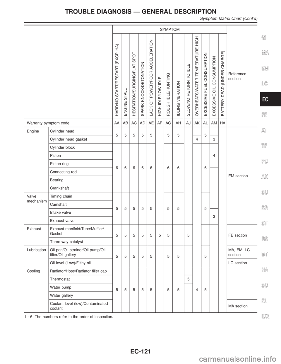
SYMPTOM
Reference
section
HARD/NO START/RESTART (EXCP. HA)
ENGINE STALL
HESITATION/SURGING/FLAT SPOT
SPARK KNOCK/DETONATION
LACK OF POWER/POOR ACCELERATION
HIGH IDLE/LOW IDLE
ROUGH IDLE/HUNTING
IDLING VIBRATION
SLOW/NO RETURN TO IDLE
OVERHEATS/WATER TEMPERATURE HIGH
EXCESSIVE FUEL CONSUMPTION
EXCESSIVE OIL CONSUMPTION
BATTERY DEAD (UNDER CHARGE)
Warranty symptom code AA AB AC AD AE AF AG AH AJ AK AL AM HA
Engine Cylinder head
55555 5 5 5
EM section Cylinder head gasket 4 3
Cylinder block
66666 6 6 64 Piston
Piston ring
Connecting rod
Bearing
Crankshaft
Valve
mechanismTiming chain
55555 5 5 5 Camshaft
Intake valve
3
Exhaust valve
Exhaust Exhaust manifold/Tube/Muffler/
Gasket
5555555 5 FEsection
Three way catalyst
Lubrication Oil pan/Oil strainer/Oil pump/Oil
filter/Oil gallery
55555 5 5 5MA, EM, LC
section
Oil level (Low)/Filthy oilLC section
Cooling Radiator/Hose/Radiator filler cap
55555 5 5 45 Thermostat 5
Water pump
Water gallery
Coolant level (low)/Contaminated
coolantMA section
1 - 6: The numbers refer to the order of inspection.
GI
MA
EM
LC
FE
AT
TF
PD
AX
SU
BR
ST
RS
BT
HA
SC
EL
IDX
TROUBLE DIAGNOSIS Ð GENERAL DESCRIPTION
Symptom Matrix Chart (Cont'd)
EC-121
Page 657 of 2395

SYMPTOM
Reference
section
HARD/NO START/RESTART (EXCP. HA)
ENGINE STALL
HESITATION/SURGING/FLAT SPOT
SPARK KNOCK/DETONATION
LACK OF POWER/POOR ACCELERATION
HIGH IDLE/LOW IDLE
ROUGH IDLE/HUNTING
IDLING VIBRATION
SLOW/NO RETURN TO IDLE
OVERHEATS/WATER TEMPERATURE HIGH
EXCESSIVE FUEL CONSUMPTION
EXCESSIVE OIL CONSUMPTION
BATTERY DEAD (UNDER CHARGE)
Warranty symptom code AA AB AC AD AE AF AG AH AJ AK AL AM HA
IVIS (INFINITI Vehicle Immobilizer System Ð
NATS)11EC-74 or EL
section
1 - 6: The numbers refer to the order of inspection.
CONSULT-II Reference Value in Data Monitor
Mode
NBEC0042Remarks:
ISpecification data are reference values.
ISpecification data are output/input values which are detected or supplied by the ECM at the connector.
* Specification data may not be directly related to their components signals/values/operations.
i.e. Adjust ignition timing with a timing light before monitoring IGN TIMING, because the monitor may show the specification data in
spite of the ignition timing not being adjusted to the specification data. This IGN TIMING monitors the data calculated by the ECM
according to the signals input from the camshaft position sensor and other ignition timing related sensors.
IIf the real-time diagnosis results are NG and the on board diagnostic system results are OK when diagnosing the mass air flow sensor,
first check to see if the fuel pump control circuit is normal.
MONITOR ITEM CONDITION SPECIFICATION
ENG SPEED
CKPS´RPM (POS)ITachometer: Connect
IRun engine and compare tachometer indication with the CONSULT-II
value.Almost the same speed as
the CONSULT-II value.
POS COUNTIEngine: Running 179 - 181
MAS A/F SE-B1IEngine: After warming up
IAir conditioner switch: ªOFFº
IShift lever: ªNº
INo-loadIdle 1.2 - 1.8V
2,500 rpm 1.6 - 2.2V
COOLAN TEMP/SIEngine: After warming up More than 70ÉC (158ÉF)
HO2S1 (B1)
HO2S1 (B2)
IEngine: After warming upMaintaining engine speed at 2,000
rpm0 - 0.3V+,Approx. 0.6 -
1.0V
HO2S1 MNTR (B1)
HO2S1 MNTR (B2)LEAN+,RICH
Changes more than 5 times
during 10 seconds.
HO2S2 (B1)
HO2S2 (B2)
IEngine: After warming upMaintaining engine speed at 2,000
rpm0 - 0.3V+,Approx. 0.6 -
1.0V
HO2S2 MNTR (B1)
HO2S2 MNTR (B2)LEAN+,RICH
TROUBLE DIAGNOSIS Ð GENERAL DESCRIPTION
Symptom Matrix Chart (Cont'd)
EC-122
Page 870 of 2395
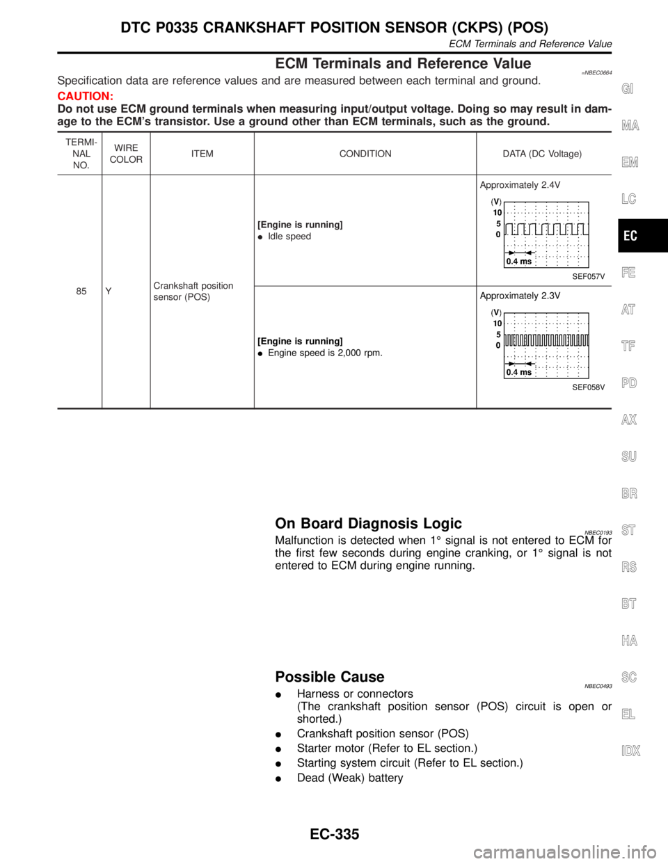
ECM Terminals and Reference Value=NBEC0664Specification data are reference values and are measured between each terminal and ground.
CAUTION:
Do not use ECM ground terminals when measuring input/output voltage. Doing so may result in dam-
age to the ECM's transistor. Use a ground other than ECM terminals, such as the ground.
TERMI-
NAL
NO.WIRE
COLORITEM CONDITION DATA (DC Voltage)
85 YCrankshaft position
sensor (POS)[Engine is running]
IIdle speedApproximately 2.4V
SEF057V
[Engine is running]
IEngine speed is 2,000 rpm.Approximately 2.3V
SEF058V
On Board Diagnosis LogicNBEC0193Malfunction is detected when 1É signal is not entered to ECM for
the first few seconds during engine cranking, or 1É signal is not
entered to ECM during engine running.
Possible CauseNBEC0493IHarness or connectors
(The crankshaft position sensor (POS) circuit is open or
shorted.)
ICrankshaft position sensor (POS)
IStarter motor (Refer to EL section.)
IStarting system circuit (Refer to EL section.)
IDead (Weak) battery
GI
MA
EM
LC
FE
AT
TF
PD
AX
SU
BR
ST
RS
BT
HA
SC
EL
IDX
DTC P0335 CRANKSHAFT POSITION SENSOR (CKPS) (POS)
ECM Terminals and Reference Value
EC-335
Page 878 of 2395
![INFINITI QX4 2001 Factory Service Manual Possible CauseNBEC0494IHarness or connectors
[The camshaft position sensor (PHASE) circuit is open or
shorted.]
ICamshaft position sensor (PHASE)
IStarter motor (Refer to SC section.)
IStarting system INFINITI QX4 2001 Factory Service Manual Possible CauseNBEC0494IHarness or connectors
[The camshaft position sensor (PHASE) circuit is open or
shorted.]
ICamshaft position sensor (PHASE)
IStarter motor (Refer to SC section.)
IStarting system](/img/42/57027/w960_57027-877.png)
Possible CauseNBEC0494IHarness or connectors
[The camshaft position sensor (PHASE) circuit is open or
shorted.]
ICamshaft position sensor (PHASE)
IStarter motor (Refer to SC section.)
IStarting system circuit (Refer to SC section.)
IDead (Weak) battery
DTC Confirmation ProcedureNBEC0200NOTE:
IPerform ªPROCEDURE FOR MALFUNCTION Aº first. If 1st
trip DTC cannot be confirmed, perform ªPROCEDURE
FOR MALFUNCTION B AND Cº.
IIf ªDTC Confirmation Procedureº has been previously
conducted, always turn ignition switch ªOFFº and wait at least
10 seconds before conducting the next test.
TESTING CONDITION:
Before performing the following procedure, confirm that bat-
tery voltage is more than 10.5V at idle.
SEF013Y
PROCEDURE FOR MALFUNCTION ANBEC0200S01With CONSULT-IINBEC0200S01011) Turn ignition switch ªONº.
2) Select ªDATA MONITORº mode with CONSULT-II.
3) Crank engine for at least 2 seconds.
4) If 1st trip DTC is detected, go to ªDiagnostic Procedureº,
EC-345.
With GSTNBEC0200S0102Follow the procedure ªWith CONSULT-IIº above.
SEF058Y
PROCEDURE FOR MALFUNCTION B AND CNBEC0200S02With CONSULT-IINBEC0200S02011) Turn ignition switch ªONº.
2) Select ªDATA MONITORº mode with CONSULT-II.
3) Start engine and run it for at least 2 seconds at idle speed.
4) If 1st trip DTC is detected, go to ªDiagnostic Procedureº,
EC-345.
With GSTNBEC0200S0202Follow the procedure ªWith CONSULT-IIº above.
GI
MA
EM
LC
FE
AT
TF
PD
AX
SU
BR
ST
RS
BT
HA
SC
EL
IDX
DTC P0340 CAMSHAFT POSITION SENSOR (CMPS) (PHASE)
Possible Cause
EC-343
Page 975 of 2395
System DescriptionNBEC0264This circuit line (LAN) is used to control the smooth shifting up and down of A/T during the hard acceleration/
deceleration.
Pulse signals are exchanged between ECM and TCM (Transmission Control Module).
Be sure to erase the malfunction information such as DTC not only in TCM but also ECM after the A/T
related repair.
ECM Terminals and Reference ValueNBEC0672Specification data are reference values and are measured between each terminal and ground.
CAUTION:
Do not use ECM ground terminals when measuring input/output voltage. Doing so may result in dam-
age to the ECM's transistor. Use a ground other than ECM terminals, such as the ground.
TERMI-
NAL
NO.WIRE
COLORITEM CONDITION DATA (DC Voltage)
114 G/RCommunication line
(LAN)[Engine is running]
IIdle speedApproximately 2V
On Board Diagnosis LogicNBEC0266Malfunction is detected when ECM receives incorrect voltage from
TCM (Transmission Control Module) continuously.
Possible CauseNBEC0517IHarness or connectors
[The communication line circuit between ECM and TCM
(Transmission Control Module) is open or shorted.]
ITCM
IDead (Weak) battery
SEF058Y
DTC Confirmation ProcedureNBEC0267NOTE:
If ªDTC Confirmation Procedureº has been previously conducted,
always turn ignition switch ªOFFº and wait at least 10 seconds
before conducting the next test.
TESTING CONDITION:
Before performing the following procedure, confirm that bat-
tery voltage is more than 10.5V at idle.
WITH CONSULT-IINBEC0267S011) Turn ignition switch ªONº.
DTC P0600 A/T COMMUNICATION LINE
System Description
EC-440
Page 1046 of 2395
On Board Diagnosis LogicNBEC0576Malfunction is detected when
(Malfunction A)120É signal is not entered to ECM for the first few
seconds during engine cranking,
(Malfunction B)120É signal is not entered to ECM during engine
running,
(Malfunction C)120É signal cycle excessively changes during
engine running.
FAIL-SAFE MODENBEC0576S01When the ECM enters the fail-safe mode, the MIL illuminates.
Detected items Engine operating condition in fail-safe mode
Crankshaft position sensor (REF)
circuitCompression TDC signal (120É signal) is controlled by camshaft position sensor (PHASE)
signal and crankshaft position sensor (POS) signal. Ignition timing will be delayed 0É to 2É.
Possible CauseNBEC0577IHarness or connectors
(The crankshaft position sensor (REF) circuit is open or
shorted.)
ICrankshaft position sensor (REF)
IStarter motor (Refer to SC section.)
IStarting system circuit (Refer to SC section.)
IDead (Weak) battery
DTC Confirmation ProcedureNBEC0578NOTE:
IPerform ªPROCEDURE FOR MALFUNCTION Aº first. If 1st
trip DTC cannot be confirmed, perform ªPROCEDURE
FOR MALFUNCTION B AND Cº.
IIf ªDTC Confirmation Procedureº has been previously
conducted, always turn ignition switch ªOFFº and wait at least
10 seconds before conducting the next test.
TESTING CONDITION:
Before performing the following procedure, confirm that bat-
tery voltage is more than 10.5V at idle.
SEF013Y
PROCEDURE FOR MALFUNCTION ANBEC0578S01With CONSULT-IINBEC0578S01011) Turn ignition switch ªONº.
2) Select ªDATA MONITORº mode with CONSULT-II.
3) Crank engine for at least 2 seconds.
4) If 1st trip DTC is detected, go to ªDiagnostic Procedureº,
EC-514.
With GSTNBEC0578S0102Follow the procedure ªWith CONSULT-IIº above.
GI
MA
EM
LC
FE
AT
TF
PD
AX
SU
BR
ST
RS
BT
HA
SC
EL
IDX
DTC P1335 CRANKSHAFT POSITION SENSOR (CKPS) (REF)
On Board Diagnosis Logic
EC-511
Page 1138 of 2395
Component DescriptionNBEC0361The malfunction information related to A/T (Automatic Transmission) is transferred through the line (circuit)
from TCM (Transmission control module) to ECM. Therefore, be sure to erase the malfunction information such
as DTC not only in TCM (Transmission control module) but also ECM after the A/T related repair.
On Board Diagnosis LogicNBEC0363Malfunction is detected when an incorrect signal from TCM (Trans-
mission control module) is sent to ECM.
Possible CauseNBEC0594IHarness or connectors
[The communication line circuit between ECM and TCM
(Transmission control module) is open or shorted.]
IDead (Weak) battery
ITCM (Transmission control module)
SEF058Y
DTC Confirmation ProcedureNBEC0364NOTE:
If ªDTC Confirmation Procedureº has been previously conducted,
always turn ignition switch ªOFFº and wait at least 10 seconds
before conducting the next test.
TESTING CONDITION:
Before performing the following procedure, confirm that bat-
tery voltage is more than 10.5V at idle.
WITH CONSULT-IINBEC0364S011) Turn ignition switch ªONº.
2) Select ªDATA MONITORº mode with CONSULT-II.
3) Start engine and wait at least 40 seconds.
4) If 1st trip DTC is detected, go to ªDTC P0600 A/T COMMUNI-
CATION LINE Diagnostic Procedureº, EC-443.
WITH GSTNBEC0364S02Follow the procedure ªWITH CONSULT-IIº above.
GI
MA
EM
LC
FE
AT
TF
PD
AX
SU
BR
ST
RS
BT
HA
SC
EL
IDX
DTC P1605 A/T DIAGNOSIS COMMUNICATION LINE
Component Description
EC-603