maintenance INFINITI QX4 2001 Factory Workshop Manual
[x] Cancel search | Manufacturer: INFINITI, Model Year: 2001, Model line: QX4, Model: INFINITI QX4 2001Pages: 2395, PDF Size: 43.2 MB
Page 2024 of 2395
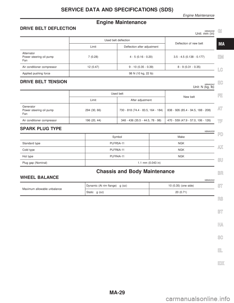
Engine Maintenance
DRIVE BELT DEFLECTIONNBMA0038Unit: mm (in)
Used belt deflection
Deflection of new belt
Limit Deflection after adjustment
Alternator
Power steering oil pump
Fan7 (0.28)4 - 5 (0.16 - 0.20) 3.5 - 4.5 (0.138 - 0.177)
Air conditioner compressor 12 (0.47) 9 - 10 (0.35 - 0.39)8 - 9 (0.31 - 0.35)
Applied pushing force 98 N (10 kg, 22 lb)
DRIVE BELT TENSIONNBMA0042Unit: N (kg, lb)
Used belt
New belt
Limit After adjustment
Generator
Power steering oil pump
Fan294 (30, 66) 730 - 818 (74.4 - 83.5, 164 - 184) 838 - 926 (85.4 - 94.5, 188 - 208)
Air conditioner compressor 196 (20, 44) 348 - 436 (35.5 - 44.5, 78 - 98) 470 - 559 (47.9 - 57.0, 106 - 126)
SPARK PLUG TYPENBMA0039
Symbol Make
Standard type PLFR5A-11 NGK
Cold type PLFR6A-11 NGK
Hot type PLFR4A-11 NGK
Plug gap (Nominal) 1.1 mm (0.043 in)
Chassis and Body Maintenance
WHEEL BALANCENBMA0040
Maximum allowable unbalanceDynamic (At rim flange) g (oz) 10 (0.35) (one side)
Static g (oz) 20 (0.71)
GI
EM
LC
EC
FE
AT
TF
PD
AX
SU
BR
ST
RS
BT
HA
SC
EL
IDX
SERVICE DATA AND SPECIFICATIONS (SDS)
Engine Maintenance
MA-29
Page 2090 of 2395

RESTRAINT SYSTEM
SECTION
RS
CONTENTS
SEAT BELTS...................................................................3
Precautions ..................................................................3
SUPPLEMENTAL RESTRAINT SYSTEM (SRS)
²AIR BAG²AND²SEAT BELT PRE-TENSIONER²
........3
PRECAUTION FOR SEAT BELT SERVICE..................3
Front Seat Belt.............................................................4
REMOVAL AND INSTALLATION.................................4
Rear Seat Belt .............................................................5
REMOVAL AND INSTALLATION.................................5
Seat Belt Inspection.....................................................7
AFTER A COLLISION.................................................7
PRELIMINARY CHECKS............................................7
SEAT BELT RETRACTOR ON-VEHICLE CHECK.........8
SEAT BELT RETRACTOR OFF-VEHICLE CHECK.......8
SUPPLEMENTAL RESTRAINT SYSTEM (SRS).........10
Precautions ................................................................10
SUPPLEMENTAL RESTRAINT SYSTEM (SRS)
²AIR BAG²AND²SEAT BELT PRE-TENSIONER²
......10
PRECAUTIONS FOR SRS²AIR BAG²AND²SEAT
BELT PRE-TENSIONER²SERVICE
...........................10
WIRING DIAGRAMS AND TROUBLE DIAGNOSIS.....10
Preparation ................................................................ 11
SPECIAL SERVICE TOOLS...................................... 11
Description .................................................................12
Seat Belt Pre-tensioner with Load Limiter.................12
Built-in Type Side Air Bag..........................................13
SRS Component Parts Location ...............................13
Maintenance Items ....................................................14
Diagnosis Sensor Unit ...............................................15
REMOVAL AND INSTALLATION...............................15
Seat Belt Pre-tensioner .............................................15
REMOVAL AND INSTALLATION...............................15
Satellite Sensor..........................................................16
REMOVAL AND INSTALLATION...............................16
Driver Air Bag Module and Spiral Cable ...................17
REMOVAL AND INSTALLATION...............................17
REMOVAL...............................................................17
INSTALLATION........................................................18
Front Passenger Air Bag Module ..............................19
REMOVAL...............................................................19
INSTALLATION........................................................20
Side Air Bag Module ..................................................21
REMOVAL...............................................................21
INSTALLATION........................................................22
Disposal of Air Bag Module and Seat Belt Pre-
tensioner ....................................................................22
CHECKING DEPLOYMENT TOOL.............................23
DEPLOYMENT PROCEDURES FOR AIR BAG
MODULE (OUTSIDE OF VEHICLE)
...........................24
DEPLOYMENT PROCEDURES FOR SEAT BELT
PRE-TENSIONER (OUTSIDE OF VEHICLE)
..............27
DEPLOYMENT OF AIR BAG MODULE AND SEAT
BELT PRE-TENSIONER WHILE MOUNTED IN
VEHICLE
.................................................................27
DISPOSING OF AIR BAG MODULE AND SEAT
BELT PRE-TENSIONER
...........................................28
Trouble Diagnoses Introduction.................................29
DIAGNOSIS FUNCTION...........................................29
DIAGNOSIS MODE FOR CONSULT-II.......................29
HOW TO CHANGE SELF-DIAGNOSIS MODE
WITH CONSULT-II
...................................................30
HOW TO CHANGE SELF-DIAGNOSIS MODE
WITHOUT CONSULT-II
............................................30
HOW TO ERASE SELF-DIAGNOSIS RESULTS.........30
How to Perform Trouble Diagnoses for Quick
and Accurate Repair ..................................................32
INFORMATION FROM CUSTOMER..........................32
PRELIMINARY CHECK............................................32
WORK FLOW..........................................................33
Schematic ..................................................................34
Wiring Diagram - SRS -.............................................35
SRS Operation Check ...............................................38
DIAGNOSTIC PROCEDURE 1..................................38
Trouble Diagnoses with CONSULT-II...................39
DIAGNOSTIC PROCEDURE 2..................................39
DIAGNOSTIC PROCEDURE 3..................................42
DIAGNOSTIC PROCEDURE 4 (CONTINUED
FROM DIAGNOSTIC PROCEDURE 2)
......................44
DIAGNOSTIC PROCEDURE 5..................................44
Trouble Diagnoses without CONSULT-II..............48
DIAGNOSTIC PROCEDURE 6..................................48
GI
MA
EM
LC
EC
FE
AT
TF
PD
AX
SU
BR
ST
BT
HA
SC
EL
IDX
Page 2092 of 2395

Precautions
SUPPLEMENTAL RESTRAINT SYSTEM (SRS) ªAIR BAGº AND ªSEAT BELT
PRE-TENSIONERº
NBRS0001The Supplemental Restraint System such as ªAIR BAGº and ªSEAT BELT PRE-TENSIONERº used along with
a seat belt, helps to reduce the risk or severity of injury to the driver and front passenger for certain types of
collision. The SRS composition which is available to INFINITI QX4 is as follows:
IFor a frontal collision
The Supplemental Restraint System consists of driver air bag module (located in the center of the steer-
ing wheel), front passenger air bag module (located on the instrument panel on passenger side), seat belt
pre-tensioners, a diagnosis sensor unit, warning lamp, wiring harness and spiral cable.
IFor a side collision
The Supplemental Restraint System consists of side air bag module (located in the outer side of front seat),
satellite sensor, diagnosis sensor unit (one of components of air bags for a frontal collision), wiring harness,
warning lamp (one of components of air bags for a frontal collision).
WARNING:
ITo avoid rendering the SRS inoperative, which could increase the risk of personal injury or death
in the event of a collision which would result in air bag inflation, all maintenance must be performed
by an authorized INFINITI dealer.
IImproper maintenance, including incorrect removal and installation of the SRS, can lead to per-
sonal injury caused by unintentional activation of the system.
IDo not use electrical test equipment on any circuit related to the SRS unless instructed to in this
Service Manual. Spiral cable and wiring harnesses covered with yellow insulation tape either just
before the harness connectors or for the complete harness are related to the SRS.
PRECAUTION FOR SEAT BELT SERVICENBRS0002CAUTION:
IBefore removing the seat belt pre-tensioner assembly, turn the ignition switch off, disconnect both
battery cables and wait at least 3 minutes.
IDo not use electrical test equipment for seat belt pre-tensioner connector.
IAfter replacing or reinstalling seat belt pre-tensioner assembly, or reconnecting seat belt pre-ten-
sioner connector, check the system function. Refer to ªSRS Operation Checkº (RS-38) for details.
IDo not use disassemble buckle or seat belt assembly.
IReplace anchor bolts if they are deformed or worn out.
INever oil tongue and buckle.
IIf any component of seat belt assembly is questionable, do not repair. Replace the whole seat belt
assembly.
IIf webbing is cut, frayed, or damaged, replace seat belt assembly.
IWhen replacing seat belt assembly, use a genuine seat belt assembly.
After A CollisionNBRS0002S01WARNING:
Inspect all seat belt assemblies including retractors and attaching hardware after any collision.
NISSAN recommends that all seat belt assemblies in use during a collision be replaced unless the
collision was minor and the belts show no damage and continue to operate properly. Failure to do so
could result in serious personal injury in an accident. Seat belt assemblies not in use during a colli-
sion should also be replaced if either damage or improper operation is noted. Seat belt pre-tensioner
should be replaced even if the seat belts are not in use during a frontal collision in which the air bags
are deployed.
Replace any seat belt assembly if:
IThe seat belt was in use at the time of a collision (except for minor collisions and the belts, retractors and
buckles show no damage and continue to operate properly).
IThe seat belt was damaged in an accident. (i.e. torn webbing, bent retractor or guide, etc.)
IThe seat belt attaching point was damaged in an accident. Inspect the seat belt attaching area for dam-
age or distortion and repair as necessary before installing a new seat belt assembly.
IAnchor bolts are deformed or worn out.
IThe seat belt pre-tensioner should be replaced even if the seat belts are not in use during the collision in
which the air bags are deployed.
GI
MA
EM
LC
EC
FE
AT
TF
PD
AX
SU
BR
ST
BT
HA
SC
EL
IDX
SEAT BELTS
Precautions
RS-3
Page 2099 of 2395
Precautions
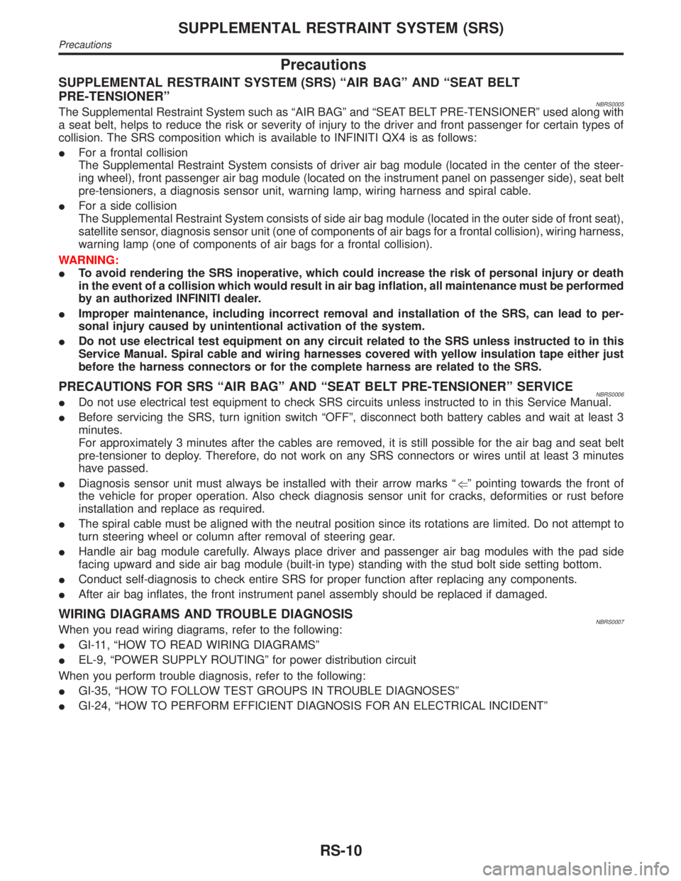
SUPPLEMENTAL RESTRAINT SYSTEM (SRS) ªAIR BAGº AND ªSEAT BELT
PRE-TENSIONERº
NBRS0005The Supplemental Restraint System such as ªAIR BAGº and ªSEAT BELT PRE-TENSIONERº used along with
a seat belt, helps to reduce the risk or severity of injury to the driver and front passenger for certain types of
collision. The SRS composition which is available to INFINITI QX4 is as follows:
IFor a frontal collision
The Supplemental Restraint System consists of driver air bag module (located in the center of the steer-
ing wheel), front passenger air bag module (located on the instrument panel on passenger side), seat belt
pre-tensioners, a diagnosis sensor unit, warning lamp, wiring harness and spiral cable.
IFor a side collision
The Supplemental Restraint System consists of side air bag module (located in the outer side of front seat),
satellite sensor, diagnosis sensor unit (one of components of air bags for a frontal collision), wiring harness,
warning lamp (one of components of air bags for a frontal collision).
WARNING:
ITo avoid rendering the SRS inoperative, which could increase the risk of personal injury or death
in the event of a collision which would result in air bag inflation, all maintenance must be performed
by an authorized INFINITI dealer.
IImproper maintenance, including incorrect removal and installation of the SRS, can lead to per-
sonal injury caused by unintentional activation of the system.
IDo not use electrical test equipment on any circuit related to the SRS unless instructed to in this
Service Manual. Spiral cable and wiring harnesses covered with yellow insulation tape either just
before the harness connectors or for the complete harness are related to the SRS.
PRECAUTIONS FOR SRS ªAIR BAGº AND ªSEAT BELT PRE-TENSIONERº SERVICENBRS0006IDo not use electrical test equipment to check SRS circuits unless instructed to in this Service Manual.
IBefore servicing the SRS, turn ignition switch ªOFFº, disconnect both battery cables and wait at least 3
minutes.
For approximately 3 minutes after the cables are removed, it is still possible for the air bag and seat belt
pre-tensioner to deploy. Therefore, do not work on any SRS connectors or wires until at least 3 minutes
have passed.
IDiagnosis sensor unit must always be installed with their arrow marks ªgº pointing towards the front of
the vehicle for proper operation. Also check diagnosis sensor unit for cracks, deformities or rust before
installation and replace as required.
IThe spiral cable must be aligned with the neutral position since its rotations are limited. Do not attempt to
turn steering wheel or column after removal of steering gear.
IHandle air bag module carefully. Always place driver and passenger air bag modules with the pad side
facing upward and side air bag module (built-in type) standing with the stud bolt side setting bottom.
IConduct self-diagnosis to check entire SRS for proper function after replacing any components.
IAfter air bag inflates, the front instrument panel assembly should be replaced if damaged.
WIRING DIAGRAMS AND TROUBLE DIAGNOSISNBRS0007When you read wiring diagrams, refer to the following:
IGI-11, ªHOW TO READ WIRING DIAGRAMSº
IEL-9, ªPOWER SUPPLY ROUTINGº for power distribution circuit
When you perform trouble diagnosis, refer to the following:
IGI-35, ªHOW TO FOLLOW TEST GROUPS IN TROUBLE DIAGNOSESº
IGI-24, ªHOW TO PERFORM EFFICIENT DIAGNOSIS FOR AN ELECTRICAL INCIDENTº
SUPPLEMENTAL RESTRAINT SYSTEM (SRS)
Precautions
RS-10
Page 2103 of 2395
SRS797-A
Maintenance ItemsNBRS0011CAUTION:
Do not use electrical test equipment to check SRS circuit.
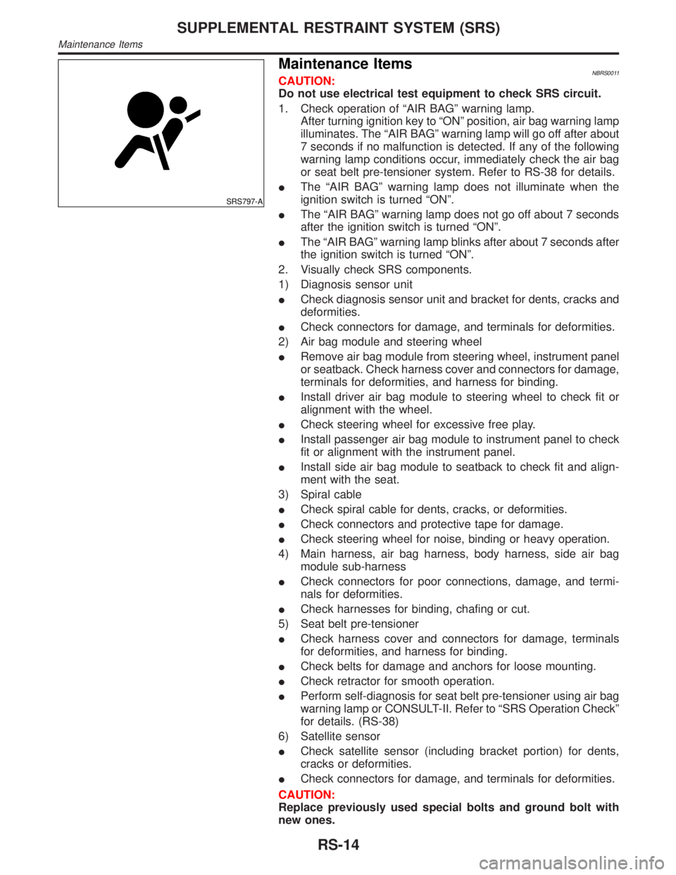
1. Check operation of ªAIR BAGº warning lamp.
After turning ignition key to ªONº position, air bag warning lamp
illuminates. The ªAIR BAGº warning lamp will go off after about
7 seconds if no malfunction is detected. If any of the following
warning lamp conditions occur, immediately check the air bag
or seat belt pre-tensioner system. Refer to RS-38 for details.
IThe ªAIR BAGº warning lamp does not illuminate when the
ignition switch is turned ªONº.
IThe ªAIR BAGº warning lamp does not go off about 7 seconds
after the ignition switch is turned ªONº.
IThe ªAIR BAGº warning lamp blinks after about 7 seconds after
the ignition switch is turned ªONº.
2. Visually check SRS components.
1) Diagnosis sensor unit
ICheck diagnosis sensor unit and bracket for dents, cracks and
deformities.
ICheck connectors for damage, and terminals for deformities.
2) Air bag module and steering wheel
IRemove air bag module from steering wheel, instrument panel
or seatback. Check harness cover and connectors for damage,
terminals for deformities, and harness for binding.
IInstall driver air bag module to steering wheel to check fit or
alignment with the wheel.
ICheck steering wheel for excessive free play.
IInstall passenger air bag module to instrument panel to check
fit or alignment with the instrument panel.
IInstall side air bag module to seatback to check fit and align-
ment with the seat.
3) Spiral cable
ICheck spiral cable for dents, cracks, or deformities.
ICheck connectors and protective tape for damage.
ICheck steering wheel for noise, binding or heavy operation.
4) Main harness, air bag harness, body harness, side air bag
module sub-harness
ICheck connectors for poor connections, damage, and termi-
nals for deformities.
ICheck harnesses for binding, chafing or cut.
5) Seat belt pre-tensioner
ICheck harness cover and connectors for damage, terminals
for deformities, and harness for binding.
ICheck belts for damage and anchors for loose mounting.
ICheck retractor for smooth operation.
IPerform self-diagnosis for seat belt pre-tensioner using air bag
warning lamp or CONSULT-II. Refer to ªSRS Operation Checkº
for details. (RS-38)
6) Satellite sensor
ICheck satellite sensor (including bracket portion) for dents,
cracks or deformities.
ICheck connectors for damage, and terminals for deformities.
CAUTION:
Replace previously used special bolts and ground bolt with
new ones.
SUPPLEMENTAL RESTRAINT SYSTEM (SRS)
Maintenance Items
RS-14
Page 2133 of 2395
![INFINITI QX4 2001 Factory Workshop Manual SRS702
10. Check that no malfunction is detected on ªSELF-DIAG
[PAST]º.
11. Touch ªBACKº key of CONSULT-II until ªSELECT SYSTEMº
appears in order to return to User mode from Diagnosis mode.
12. INFINITI QX4 2001 Factory Workshop Manual SRS702
10. Check that no malfunction is detected on ªSELF-DIAG
[PAST]º.
11. Touch ªBACKº key of CONSULT-II until ªSELECT SYSTEMº
appears in order to return to User mode from Diagnosis mode.
12.](/img/42/57027/w960_57027-2132.png)
SRS702
10. Check that no malfunction is detected on ªSELF-DIAG
[PAST]º.
11. Touch ªBACKº key of CONSULT-II until ªSELECT SYSTEMº
appears in order to return to User mode from Diagnosis mode.
12. Turn ignition switch ªOFFº, then turn off and disconnect CON-
SULT-II.
13. Go to ªSRS Operation Checkº, page RS-38 to check SRS
operation by using ªAIR BAGº warning lamp with User mode.
DIAGNOSTIC PROCEDURE 4 (CONTINUED FROM
DIAGNOSTIC PROCEDURE 2)
NBRS0045S03Inspecting SRS malfunctioning record
1 CONSIDER POSSIBILITY OF NOT ERASING SELF-DIAGNOSTIC RESULT AFTER REPAIRING
Is it the first time for maintenance of SRS?
YesorNo
Ye s©Go to DIAGNOSTIC PROCEDURE 5 (RS-44).
No©Self-diagnostic result ªSELF-DIAG [PAST]º (previously stored in the memory) might not
be erased after repair. Go to DIAGNOSTIC PROCEDURE 3, step 8 (RS-42).
SRS844
DIAGNOSTIC PROCEDURE 5NBRS0045S04Inspecting SRS intermittent malfunction by using CONSULT-II
Ð Diagnosis mode
1. Turn ignition switch ªOFFº.
2. Connect CONSULT-II to Data link connector.
SRS695
3. Turn ignition switch ªONº.
4. Touch ªSTARTº.
SUPPLEMENTAL RESTRAINT SYSTEM (SRS)
Trouble Diagnoses with CONSULT-II (Cont'd)
RS-44
Page 2144 of 2395

ªAIR BAGº warning lamp operation Ð User mode Ð SRS condition Reference item
MRS095A
No malfunction is
detected.
No further action is neces-
sary.Ð
MRS096A
The system is malfunction-
ing and needs to be
repaired as indicated.Go to DIAGNOSTIC PRO-
CEDURE 6 (RS-48).
MRS097A
Air bag is deployed.
Seat belt pre-tensioner is
deployed.Go to COLLISION DIAG-
NOSIS (RS-59).
Air bag fuse, diagnosis
sensor unit or harness is
malfunctioning and needs
to be repaired.Go to DIAGNOSTIC PRO-
CEDURE 9 RS-56).
MRS098A
One of the following has
occurred and needs to be
repaired.
IMeter fuse is blown.
IªAIR BAGº warning
lamp circuit has open or
short.
IDiagnosis sensor unit is
malfunctioning.Go to DIAGNOSTIC PRO-
CEDURE 10 (RS-58).
DIAGNOSTIC PROCEDURE 8 (CONTINUED FROM
DIAGNOSTIC PROCEDURE 6)
NBRS0046S03Inspecting SRS malfunctioning record
1 CONSIDER POSSIBILITY OF NOT ERASING SELF-DIAGNOSTIC RESULT AFTER REPAIRING
Is it the first time for maintenance of SRS?
YesorNo
Ye s©Go to DIAGNOSTIC PROCEDURE 5 (RS-44). (Further inspection cannot be performed
without CONSULT-II.)
No©Diagnosis results (previously stored in the memory) might not be erased after repair. Go
to DIAGNOSTIC PROCEDURE 7, step 5 (RS-53).
GI
MA
EM
LC
EC
FE
AT
TF
PD
AX
SU
BR
ST
BT
HA
SC
EL
IDX
SUPPLEMENTAL RESTRAINT SYSTEM (SRS)
Trouble Diagnoses without CONSULT-II (Cont'd)
RS-55
Page 2153 of 2395
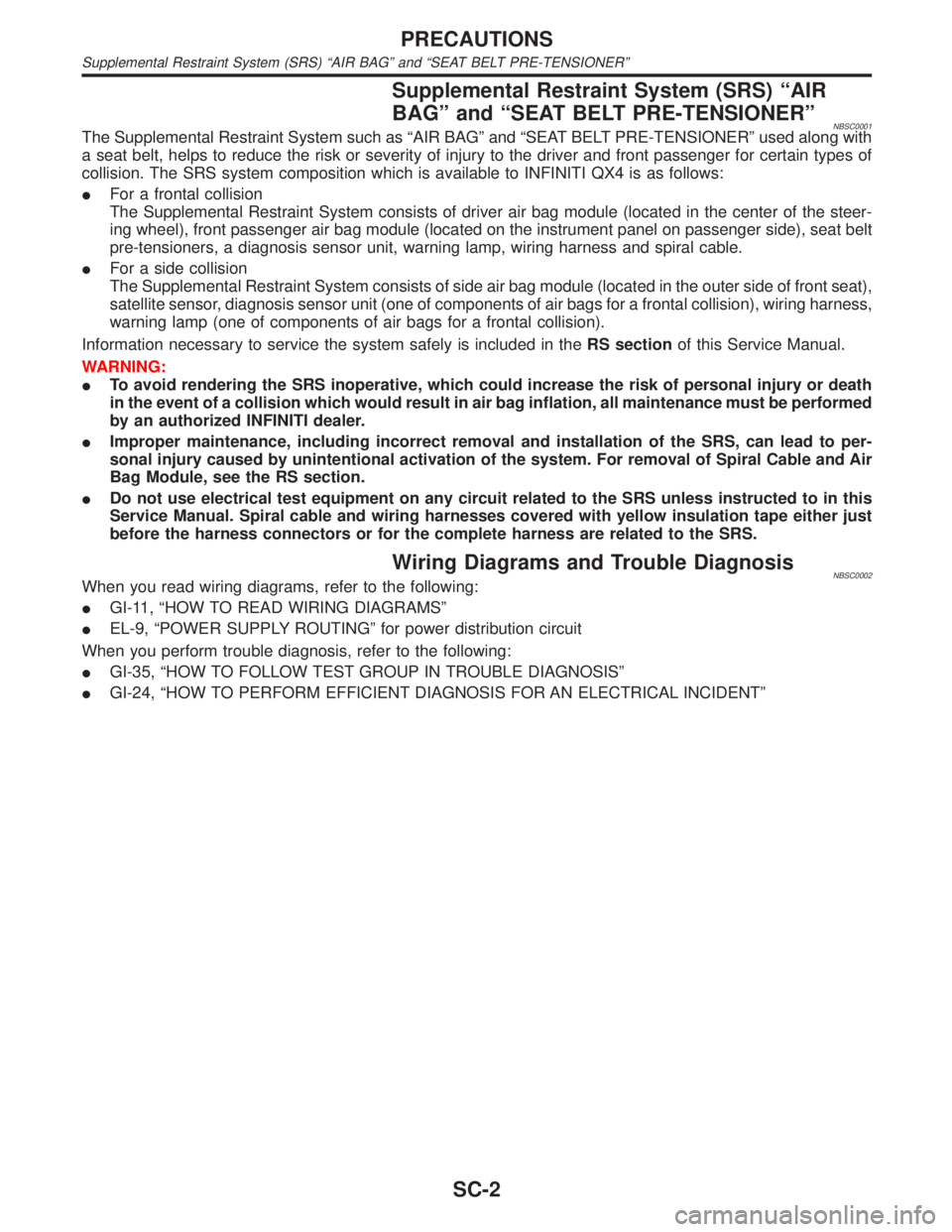
Supplemental Restraint System (SRS) ªAIR
BAGº and ªSEAT BELT PRE-TENSIONERº
NBSC0001The Supplemental Restraint System such as ªAIR BAGº and ªSEAT BELT PRE-TENSIONERº used along with
a seat belt, helps to reduce the risk or severity of injury to the driver and front passenger for certain types of
collision. The SRS system composition which is available to INFINITI QX4 is as follows:
IFor a frontal collision
The Supplemental Restraint System consists of driver air bag module (located in the center of the steer-
ing wheel), front passenger air bag module (located on the instrument panel on passenger side), seat belt
pre-tensioners, a diagnosis sensor unit, warning lamp, wiring harness and spiral cable.
IFor a side collision
The Supplemental Restraint System consists of side air bag module (located in the outer side of front seat),
satellite sensor, diagnosis sensor unit (one of components of air bags for a frontal collision), wiring harness,
warning lamp (one of components of air bags for a frontal collision).
Information necessary to service the system safely is included in theRS sectionof this Service Manual.
WARNING:
ITo avoid rendering the SRS inoperative, which could increase the risk of personal injury or death
in the event of a collision which would result in air bag inflation, all maintenance must be performed
by an authorized INFINITI dealer.
IImproper maintenance, including incorrect removal and installation of the SRS, can lead to per-
sonal injury caused by unintentional activation of the system. For removal of Spiral Cable and Air
Bag Module, see the RS section.
IDo not use electrical test equipment on any circuit related to the SRS unless instructed to in this
Service Manual. Spiral cable and wiring harnesses covered with yellow insulation tape either just
before the harness connectors or for the complete harness are related to the SRS.
Wiring Diagrams and Trouble DiagnosisNBSC0002When you read wiring diagrams, refer to the following:
IGI-11, ªHOW TO READ WIRING DIAGRAMSº
IEL-9, ªPOWER SUPPLY ROUTINGº for power distribution circuit
When you perform trouble diagnosis, refer to the following:
IGI-35, ªHOW TO FOLLOW TEST GROUP IN TROUBLE DIAGNOSISº
IGI-24, ªHOW TO PERFORM EFFICIENT DIAGNOSIS FOR AN ELECTRICAL INCIDENTº
PRECAUTIONS
Supplemental Restraint System (SRS) ªAIR BAGº and ªSEAT BELT PRE-TENSIONERº
SC-2
Page 2155 of 2395
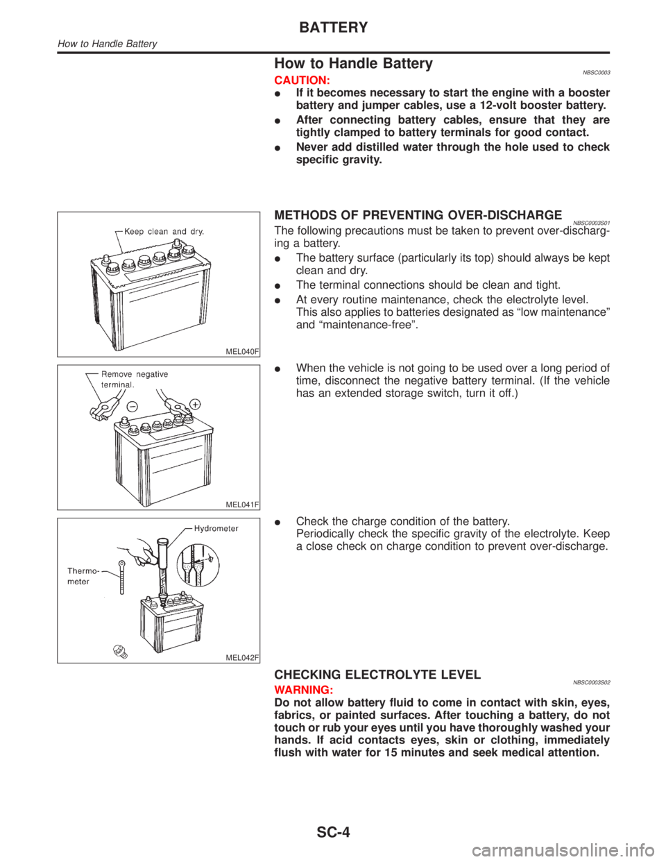
How to Handle BatteryNBSC0003CAUTION:
IIf it becomes necessary to start the engine with a booster
battery and jumper cables, use a 12-volt booster battery.
IAfter connecting battery cables, ensure that they are
tightly clamped to battery terminals for good contact.
INever add distilled water through the hole used to check
specific gravity.
MEL040F
METHODS OF PREVENTING OVER-DISCHARGENBSC0003S01The following precautions must be taken to prevent over-discharg-
ing a battery.
IThe battery surface (particularly its top) should always be kept
clean and dry.
IThe terminal connections should be clean and tight.
IAt every routine maintenance, check the electrolyte level.
This also applies to batteries designated as ªlow maintenanceº
and ªmaintenance-freeº.
MEL041F
IWhen the vehicle is not going to be used over a long period of
time, disconnect the negative battery terminal. (If the vehicle
has an extended storage switch, turn it off.)
MEL042F
ICheck the charge condition of the battery.
Periodically check the specific gravity of the electrolyte. Keep
a close check on charge condition to prevent over-discharge.
CHECKING ELECTROLYTE LEVELNBSC0003S02WARNING:
Do not allow battery fluid to come in contact with skin, eyes,
fabrics, or painted surfaces. After touching a battery, do not
touch or rub your eyes until you have thoroughly washed your
hands. If acid contacts eyes, skin or clothing, immediately
flush with water for 15 minutes and seek medical attention.
BATTERY
How to Handle Battery
SC-4
Page 2183 of 2395
Supplemental Restraint System (SRS) ªAIR
BAGº and ªSEAT BELT PRE-TENSIONERº
NBST0044The Supplemental Restraint System such as ªAIR BAGº and ªSEAT BELT PRE-TENSIONERº used along with
a seat belt, helps to reduce the risk or severity of injury to the driver and front passenger for certain types of
collision. The SRS system composition which is available to INFINITI QX4 is as follows:
IFor a frontal collision
The Supplemental Restraint System consists of driver air bag module (located in the center of the steer-
ing wheel), front passenger air bag module (located on the instrument panel on passenger side), seat belt
pre-tensioners, a diagnosis sensor unit, warning lamp, wiring harness and spiral cable.
IFor a side collision
The Supplemental Restraint System consists of side air bag module (located in the outer side of front seat),
satellite sensor, diagnosis sensor unit (one of components of air bags for a frontal collision), wiring harness,
warning lamp (one of components of air bags for a frontal collision).
Information necessary to service the system safely is included in theRS sectionof this Service Manual.
WARNING:
ITo avoid rendering the SRS inoperative, which could increase the risk of personal injury or death
in the event of a collision which would result in air bag inflation, all maintenance must be performed
by an authorized INFINITI dealer.
IImproper maintenance, including incorrect removal and installation of the SRS, can lead to per-
sonal injury caused by unintentional activation of the system. For removal of Spiral Cable and Air
Bag Module, see the RS section.
IDo not use electrical test equipment on any circuit related to the SRS unless instructed to in this
Service Manual. Spiral cable and wiring harnesses covered with yellow insulation tape either just
before the harness connectors or for the complete harness are related to the SRS.
Precautions for Steering SystemNBST0002IBefore disassembly, thoroughly clean the outside of the unit.
IDisassembly should be done in a clean work area. It is important to prevent the internal parts from
becoming contaminated by dirt or other foreign matter.
IPlace disassembled parts in order, on a parts rack, for easier and proper assembly.
IUse nylon cloths or paper towels to clean the parts; common shop rags can leave lint that might
interfere with their operation.
IBefore inspection or reassembly, carefully clean all parts with a general purpose, non-flammable
solvent.
IBefore assembly, apply a coat of recommended power steering fluid* to hydraulic parts. Vaseline
may be applied to O-rings and seals. Do not use any grease.
IReplace all gaskets, seals and O-rings. Avoid damaging O-rings, seals and gaskets during instal-
lation. Perform functional tests whenever designated.
*: Genuine Nissan PSF II or equivalent. Refer to MA-11, ªFluids and Lubricantsº.
PRECAUTIONS
Supplemental Restraint System (SRS) ªAIR BAGº and ªSEAT BELT PRE-TENSIONERº
ST-2