manual transmission INFINITI QX4 2001 Factory Service Manual
[x] Cancel search | Manufacturer: INFINITI, Model Year: 2001, Model line: QX4, Model: INFINITI QX4 2001Pages: 2395, PDF Size: 43.2 MB
Page 93 of 2395

Items Symptom Condition Diagnostic Item Reference Page
Slips/Will Not
EngageRaces extremely
fast or slips in
changing from D
4or D3to D1when
depressing pedal.ON vehicle1. Fluid level AT-59
2. Throttle position sensor (Adjustment) EC-174
3. Line pressure test AT-62
4. Line pressure solenoid valve AT-162
5. Control valve assembly AT-273
OFF vehicle6. Forward clutch AT-320
7. Forward one-way clutch AT-330
8. Low one-way clutch AT-328
Vehicle will not
run in any posi-
tion.ON vehicle1. Fluid level AT-59
2. Manual control linkage adjustment AT-276
3. Line pressure test AT-62
4. Line pressure solenoid valve AT-162
OFF vehicle5. Oil pump AT-297
6. High clutch AT-317
7. Brake band AT-333
8. Low & reverse brake AT-324
9. Torque converter AT-286
10. Parking pawl components AT-337
NOT USEDEngine cannot be
started in P and N
positions.
AT-221ON vehicle1. Ignition switch and starter EL-9, and SC-10
2. Manual control linkage adjustment AT-276
3. Park/neutral position (PNP) switch
adjustmentAT-276
Engine starts in
positions other
than P and N.
AT-221ON vehicle1. Manual control linkage adjustment AT-276
2. Park/neutral position (PNP) switch
adjustmentAT-276
Transmission
noise in P and N
positions.ON vehicle1. Fluid level AT-59
2. Line pressure test AT-62
3. Throttle position sensor (Adjustment) EC-174
4. Vehicle speed sensor´A/T (Revolution
sensor) and vehicle speed sensor´MTRAT- 111 , 1 9 7
5. Engine speed signal AT-116
OFF vehicle6. Oil pump AT-297
7. Torque converter AT-286
Vehicle moves
when changing
into P position or
parking gear does
not disengage
when shifted out
of P position.
AT-222ON vehicle 1. Manual control linkage adjustment AT-276
OFF vehicle 2. Parking pawl components AT-337
TROUBLE DIAGNOSIS Ð GENERAL DESCRIPTION
Symptom Chart (Cont'd)
AT-88
Page 95 of 2395

Items Symptom Condition Diagnostic Item Reference Page
NOT USEDMaximum speed
not attained.
Acceleration poor.ON vehicle1. Fluid level AT-59
2. Park/neutral position (PNP) switch
adjustmentAT-276
3. Shift solenoid valve A AT-168
4. Shift solenoid valve B AT-172
5. Control valve assembly AT-273
OFF vehicle6. Reverse clutch AT-314
7. High clutch AT-317
8. Brake band AT-333
9. Low & reverse brake AT-324
10. Oil pump AT-297
11. Torque converter AT-286
Transmission
noise in D, 2, 1
and R positions.ON vehicle 1. Fluid level AT-59
ON vehicle 2. Torque converter AT-286
Engine brake
does not operate
in ª1º position.
AT-252ON vehicle1. Park/neutral position (PNP) switch
adjustmentAT-276
2. Manual control linkage adjustment AT-276
3. Throttle position sensor (Adjustment) EC-174
4. Vehicle speed sensor´A/T (Revolution
sensor) and vehicle speed sensor´MTRAT- 111 , 1 9 7
5. Shift solenoid valve A AT-168
6. Control valve assembly AT-273
7. Overrun clutch solenoid valve AT-185
OFF vehicle8. Overrun clutch AT-320
9. Low & reverse brake AT-324
Transmission
overheats.ON vehicle1. Fluid level AT-59
2. Engine idling rpm EC-431
3. Throttle position sensor (Adjustment) EC-174
4. Line pressure test AT-62
5. Line pressure solenoid valve AT-162
6. Control valve assembly AT-273
OFF vehicle7. Oil pump AT-297
8. Reverse clutch AT-314
9. High clutch AT-317
10. Brake band AT-333
11. Forward clutch AT-320
12. Overrun clutch AT-320
13. Low & reverse brake AT-324
14. Torque converter AT-286
TROUBLE DIAGNOSIS Ð GENERAL DESCRIPTION
Symptom Chart (Cont'd)
AT-90
Page 281 of 2395
SAT551J
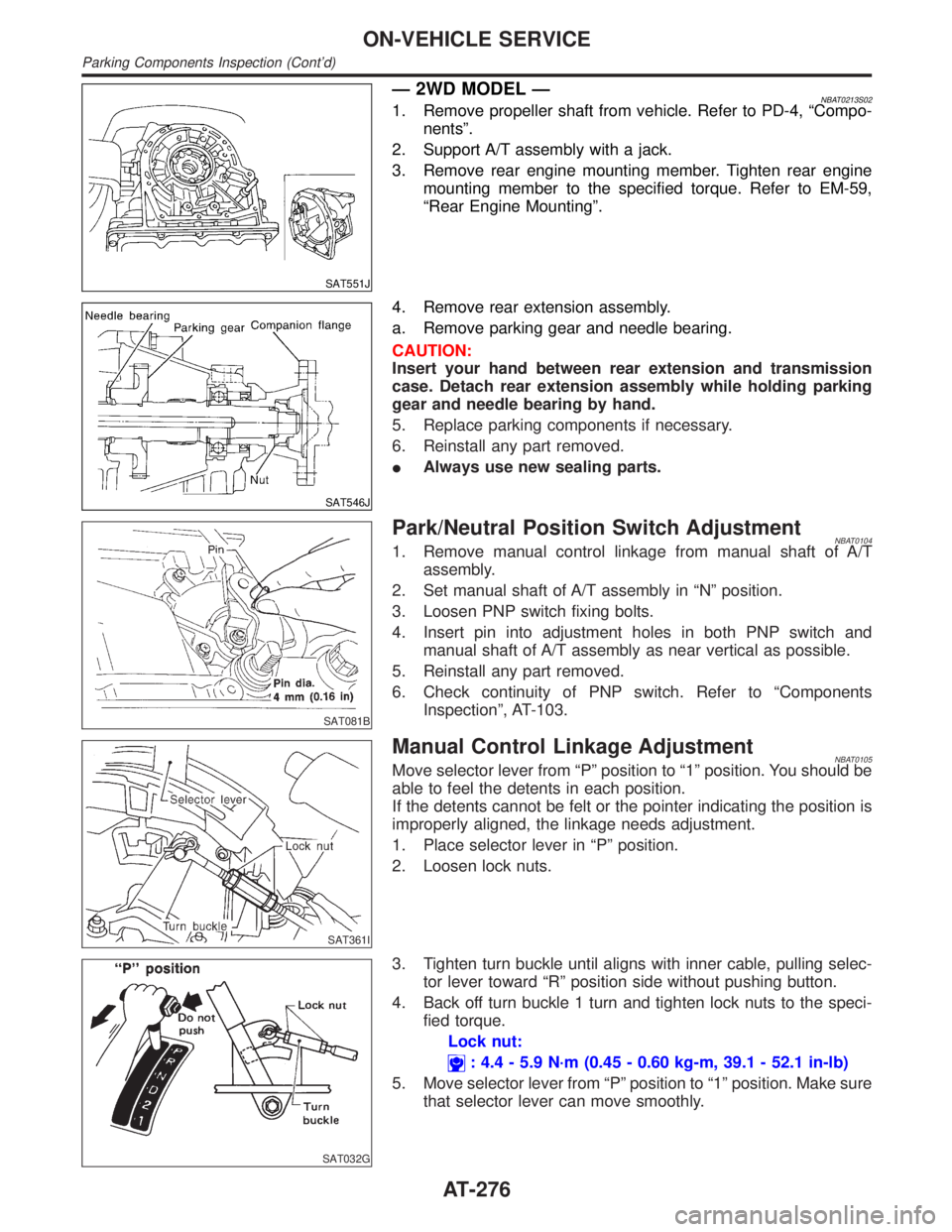
Ð 2WD MODEL ÐNBAT0213S021. Remove propeller shaft from vehicle. Refer to PD-4, ªCompo-
nentsº.
2. Support A/T assembly with a jack.
3. Remove rear engine mounting member. Tighten rear engine
mounting member to the specified torque. Refer to EM-59,
ªRear Engine Mountingº.
SAT546J
4. Remove rear extension assembly.
a. Remove parking gear and needle bearing.
CAUTION:
Insert your hand between rear extension and transmission
case. Detach rear extension assembly while holding parking
gear and needle bearing by hand.
5. Replace parking components if necessary.
6. Reinstall any part removed.
IAlways use new sealing parts.
SAT081B
Park/Neutral Position Switch AdjustmentNBAT01041. Remove manual control linkage from manual shaft of A/T
assembly.
2. Set manual shaft of A/T assembly in ªNº position.
3. Loosen PNP switch fixing bolts.
4. Insert pin into adjustment holes in both PNP switch and
manual shaft of A/T assembly as near vertical as possible.
5. Reinstall any part removed.
6. Check continuity of PNP switch. Refer to ªComponents
Inspectionº, AT-103.
SAT361I
Manual Control Linkage AdjustmentNBAT0105Move selector lever from ªPº position to ª1º position. You should be
able to feel the detents in each position.
If the detents cannot be felt or the pointer indicating the position is
improperly aligned, the linkage needs adjustment.
1. Place selector lever in ªPº position.
2. Loosen lock nuts.
SAT032G
3. Tighten turn buckle until aligns with inner cable, pulling selec-
tor lever toward ªRº position side without pushing button.
4. Back off turn buckle 1 turn and tighten lock nuts to the speci-
fied torque.
Lock nut:
: 4.4 - 5.9 N´m (0.45 - 0.60 kg-m, 39.1 - 52.1 in-lb)
5. Move selector lever from ªPº position to ª1º position. Make sure
that selector lever can move smoothly.
ON-VEHICLE SERVICE
Parking Components Inspection (Cont'd)
AT-276
Page 293 of 2395

SAT353B
b. Remove bolts A and B, and remove control valve assembly
from transmission.
Bolt symbol Length mm (in)
A 33 (1.30)
B 45 (1.77)
SAT026B
c. Remove solenoid connector.
IBe careful not to damage connector.
SAT127B
d. Remove manual valve from control valve assembly.
SAT128B
12. Remove terminal cord assembly from transmission case while
pushing on stopper.
IBe careful not to damage cord.
IDo not remove terminal cord assembly unless it is dam-
aged.
DISASSEMBLY
AT-288
Page 300 of 2395
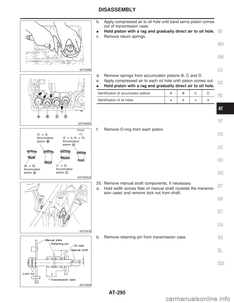
SAT039B
b. Apply compressed air to oil hole until band servo piston comes
out of transmission case.
IHold piston with a rag and gradually direct air to oil hole.
c. Remove return springs.
SAT040BA
d. Remove springs from accumulator pistons B, C and D.
e. Apply compressed air to each oil hole until piston comes out.
IHold piston with a rag and gradually direct air to oil hole.
Identification of accumulator pistons A B C D
Identification of oil holes a b c d
SAT523GA
f. Remove O-ring from each piston.
SAT041B
25. Remove manual shaft components, if necessary.
a. Hold width across flats of manual shaft (outside the transmis-
sion case) and remove lock nut from shaft.
SAT042B
b. Remove retaining pin from transmission case.
GI
MA
EM
LC
EC
FE
TF
PD
AX
SU
BR
ST
RS
BT
HA
SC
EL
IDX
DISASSEMBLY
AT-295
Page 301 of 2395
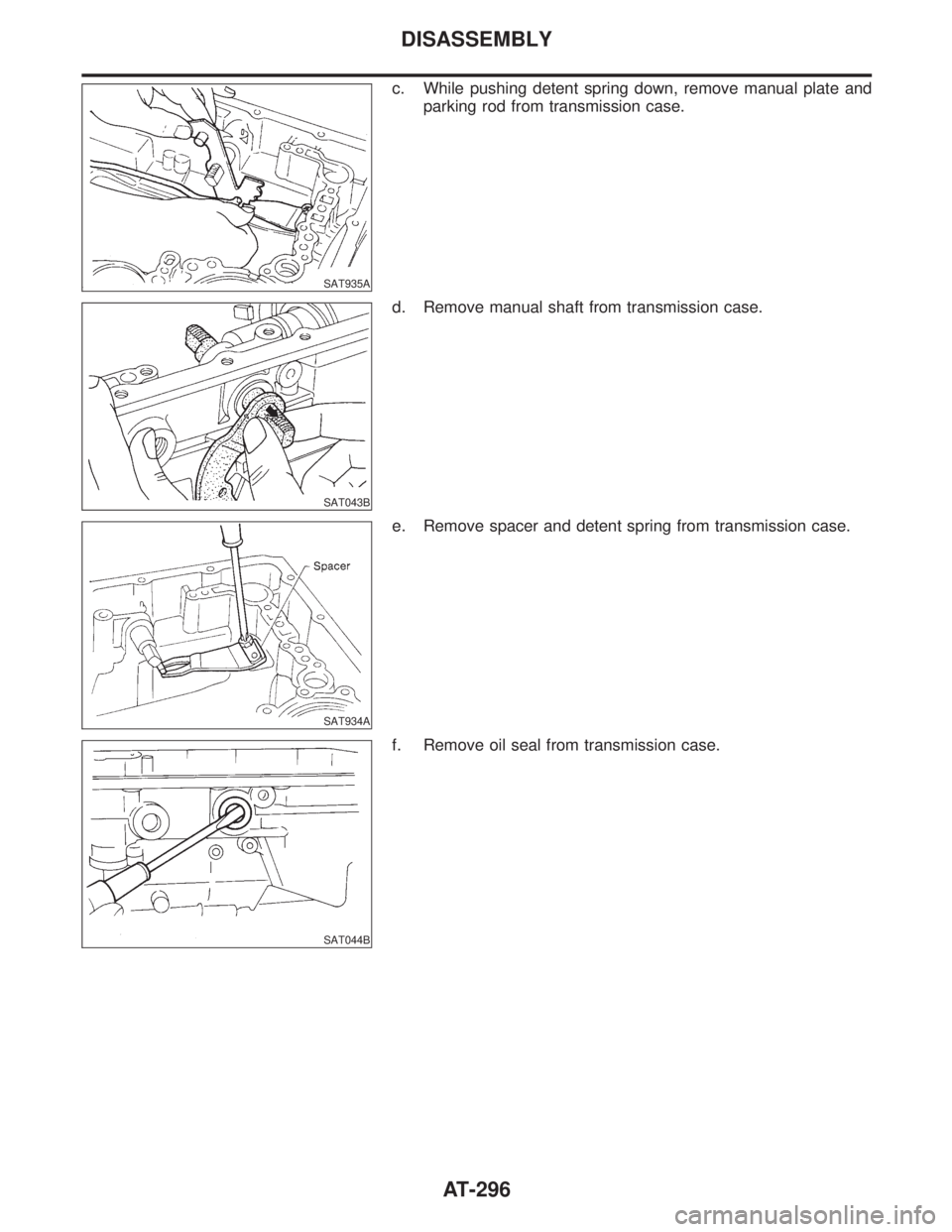
SAT935A
c. While pushing detent spring down, remove manual plate and
parking rod from transmission case.
SAT043B
d. Remove manual shaft from transmission case.
SAT934A
e. Remove spacer and detent spring from transmission case.
SAT044B
f. Remove oil seal from transmission case.
DISASSEMBLY
AT-296
Page 344 of 2395

SAT931A
Assembly (1)NBAT01551. Install manual shaft components.
a. Install oil seal onto manual shaft.
IApply ATF to oil seal.
IWrap threads of manual shaft with masking tape.
b. Insert manual shaft and oil seal as a unit into transmission
case.
c. Remove masking tape.
SAT932A
d. Push oil seal evenly and install it onto transmission case.
SAT933A
e. Align groove in shaft with retaining pin hole, then retaining pin
into position as shown in figure at left.
SAT901E
f. Install detent spring and spacer.
g. While pushing detent spring down, install manual plate onto
manual shaft.
SAT936A
h. Install lock nuts onto manual shaft.
GI
MA
EM
LC
EC
FE
TF
PD
AX
SU
BR
ST
RS
BT
HA
SC
EL
IDX
ASSEMBLY
Assembly (1)
AT-339
Page 357 of 2395

SAT001B
7. Install turbine revolution sensor.
8. Adjust brake band.
a. Tighten anchor end bolt to specified torque.
Anchor end bolt:
:4-6N´m(0.4 - 0.6 kg-m, 35 - 52 in-lb)
b. Back off anchor end bolt two and a half turns.
SAT002B
c. While holding anchor end bolt, tighten lock nut.
Ancher end bolt nut:
: 41 - 50 N´m (4.1 - 5.2 kg-m, 30 - 37 ft-lb)
SAT115B
9. Install terminal cord assembly.
a. Install O-ring on terminal cord assembly.
IApply petroleum jelly to O-ring.
b. Compress terminal cord assembly stopper and install terminal
cord assembly on transmission case.
SAT004BA
10. Install control valve assembly.
a. Install accumulator piston return springs B, C and D.
Free length of return springs:
Refer to SDS, AT-357.
SAT005B
b. Install manual valve on control valve.
IApply ATF to manual valve.
ASSEMBLY
Assembly (2) (Cont'd)
AT-352
Page 359 of 2395
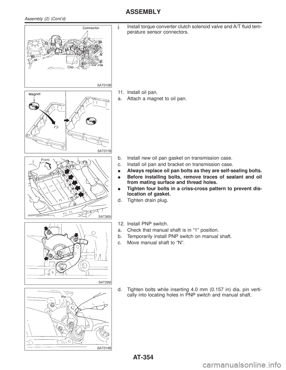
SAT010B
j. Install torque converter clutch solenoid valve and A/T fluid tem-
perature sensor connectors.
SAT011B
11. Install oil pan.
a. Attach a magnet to oil pan.
SAT365I
b. Install new oil pan gasket on transmission case.
c. Install oil pan and bracket on transmission case.
IAlways replace oil pan bolts as they are self-sealing bolts.
IBefore installing bolts, remove traces of sealant and oil
from mating surface and thread holes.
ITighten four bolts in a criss-cross pattern to prevent dis-
location of gasket.
d. Tighten drain plug.
SAT299I
12. Install PNP switch.
a. Check that manual shaft is in ª1º position.
b. Temporarily install PNP switch on manual shaft.
c. Move manual shaft to ªNº.
SAT014B
d. Tighten bolts while inserting 4.0 mm (0.157 in) dia. pin verti-
cally into locating holes in PNP switch and manual shaft.
ASSEMBLY
Assembly (2) (Cont'd)
AT-354
Page 549 of 2395
Supplemental Restraint System (SRS) ªAIR
BAGº and ªSEAT BELT PRE-TENSIONERº
NBEC0002The Supplemental Restraint System such as ªAIR BAGº and ªSEAT BELT PRE-TENSIONERº used along with
a seat belt, helps to reduce the risk or severity of injury to the driver and front passenger for certain types of
collision. The SRS system composition which is available to INFINITI QX4 is as follows:
IFor a frontal collision
The Supplemental Restraint System consists of driver air bag module (located in the center of the steer-
ing wheel), front passenger air bag module (located on the instrument panel on passenger side), seat belt
pre-tensioners, a diagnosis sensor unit, warning lamp, wiring harness and spiral cable.
IFor a side collision
The Supplemental Restraint System consists of front side air bag module (located in the outer side of front
seat), satellite sensor, diagnosis sensor unit (one of components of air bags for a frontal collision), wiring
harness, warning lamp (one of components of air bags for a frontal collision).
Information necessary to service the system safely is included in theRS sectionof this Service Manual.
WARNING:
ITo avoid rendering the SRS inoperative, which could increase the risk of personal injury or death
in the event of a collision which would result in air bag inflation, all maintenance must be performed
by an authorized INFINITI dealer.
IImproper maintenance, including incorrect removal and installation of the SRS, can lead to per-
sonal injury caused by unintentional activation of the system. For removal of Spiral Cable and Air
Bag Module, see the RS section.
IDo not use electrical test equipment on any circuit related to the SRS unless instructed to in this
Service Manual. Spiral cable and wiring harnesses covered with yellow insulation tape either just
before the harness connectors or for the complete harness are related to the SRS.
Precautions for On Board Diagnostic (OBD)
System of Engine and A/T
NBEC0003The ECM has an on board diagnostic system. It will light up the malfunction indicator lamp (MIL) to warn the
driver of a malfunction causing emission deterioration.
CAUTION:
IBe sure to turn the ignition switch OFF and disconnect the negative battery terminal before any
repair or inspection work. The open/short circuit of related switches, sensors, solenoid valves, etc.
will cause the MIL to light up.
IBe sure to connect and lock the connectors securely after work. A loose (unlocked) connector will
cause the MIL to light up due to the open circuit. (Be sure the connector is free from water, grease,
dirt, bent terminals, etc.)
ICertain systems and components, especially those related to OBD, may use a new style slide-
locking type harness connector. For description and how to disconnect, refer to EL-6, ªHARNESS
CONNECTOR (SLIDE-LOCKING TYPE)º.
IBe sure to route and secure the harnesses properly after work. The interference of the harness with
a bracket, etc. may cause the MIL to light up due to the short circuit.
IBe sure to connect rubber tubes properly after work. A misconnected or disconnected rubber tube
may cause the MIL to light up due to the malfunction of the fuel injection system, etc.
IBe sure to erase the unnecessary malfunction information (repairs completed) from the ECM and
TCM (Transmission control module) before returning the vehicle to the customer.
PRECAUTIONS
Supplemental Restraint System (SRS) ªAIR BAGº and ªSEAT BELT PRE-TENSIONERº
EC-14