IDX INFINITI QX4 2001 Factory Service Manual
[x] Cancel search | Manufacturer: INFINITI, Model Year: 2001, Model line: QX4, Model: INFINITI QX4 2001Pages: 2395, PDF Size: 43.2 MB
Page 1566 of 2395

System Setting (When IVCS Unit is Replaced)NBEL0187DESCRIPTIONNBEL0187S01When the IVCS unit is replaced, carry out the following data set-
tings.
IPhone setup Ð Data setting regarding NAM (Number Assign-
ment Module)
IPhone number Ð Phone number setting
NOTE:
IData must not be updated without prior approval from the
customer.
INAM and phone number can be programed by using hand-
set. For details, refer to the handset operation manual.
IThe IVCS unit does not permit updating of NAM more than
15 times.
WORK FLOWNBEL0187S02
SEL108WC
*1: EL-382 *2: EL-383 *3: EL-384
NOTE:
IIf a Communicator Response Center operator does not
come on line even though the system activates, the sys-
tem may not be properly configured. Call the Communica-
tor Response Center at 1-888-427-4812 to verify the con-
figuration information.
GI
MA
EM
LC
EC
FE
AT
TF
PD
AX
SU
BR
ST
RS
BT
HA
SC
IDX
INFINITI COMMUNICATOR (IVCS)
System Setting (When IVCS Unit is Replaced)
EL-381
Page 1568 of 2395

SEL460W
6. Touch ªOKº.
7. Carry out the next system setting or contact Communicator
Response Center and information them that data has been
updated or the IVCS unit has been replaced. For details, refer
to EL-381.
NOTE:
Whenever the phone number is updated or the IVCS unit is
replaced, the INFINITI Communicator system automatically
contacts the Communicator Response Center the first time the
vehicle is started.
SEL461W
PHONE SET UPNBEL0187S041. Touch ªCONFIGURATIONº.
2. Touch ªPHONE SET UPº.
SEL716W
3. Touch ªWRITEº or ªREWRITEº.
IIf no data is previously memorized, the display shows ªThis
unit has no required data programmedº.
SEL463W
IIf NAM (Number Assignment Module) data is previously
memorized, the display shows the current NAM data.
ITo erase the NAM, touch ªERASEº.
SEL464W
4. Input new NAM data.
ISYS ID (Carrier system ID number) Ð Available number: 0 to
32765
IGR ID (Group ID mark) Ð Available number: 0 to 15
IOVERLOAD CLASS (Access overload class) Ð Available
number: 0 to 15
ISECURITY CODE (User security code)
IUNLOCK CODE
IINIT PAGE CH (Initial paging channel)
GI
MA
EM
LC
EC
FE
AT
TF
PD
AX
SU
BR
ST
RS
BT
HA
SC
IDX
INFINITI COMMUNICATOR (IVCS)
System Setting (When IVCS Unit is Replaced) (Cont'd)
EL-383
Page 1570 of 2395

Component Parts LocationNBEL0227
SEL508X
GI
MA
EM
LC
EC
FE
AT
TF
PD
AX
SU
BR
ST
RS
BT
HA
SC
IDX
NAVIGATION SYSTEM
Component Parts Location
EL-385
Page 1572 of 2395

SEL685V
Map MatchingNBEL0228S0102Map matching allows the driver to compare the sensed vehicle
location data with the road map contained in the CD-ROM drive.
Vehicle position is marked on the CD-ROM map. This permits the
driver to accurately determine his/her present position on the high-
way and to make appropriate course decisions.
When GPS data reception is poor during travel, the vehicle posi-
tion is not amended. At this time, manual manipulation of the CD-
ROM map position marker is required.
SEL686V
Map matching permits the driver to make priority judgments about
possible appropriate roads other than the one currently being trav-
eled.
If there is an error in the distance or direction of travel, there will
also be an error in the relative position of other routes. When two
routes are closely parallel to one another, the indicated position for
both routes will be nearly the same priority. This is so that, slight
changes in the steering direction may cause the marker to indicate
both routes alternately.
SEL687V
Newly constructed roads may not appear on the CD-ROM map. In
this case, map matching is not possible. Changes in the course of
a road will also prevent accurate map matching.
When driving on a road not shown on the CD-ROM map, the posi-
tion marker used for map matching may indicate a different route.
Even after returning to a route shown on the map, the position
marker may jump to the position currently detected.
SEL526V
GPS (Global Positioning System)NBEL0228S0103GPS is the global positioning system developed and operated by
the US Department of Defense. GPS satellites (NAVSTAR) trans-
mit radio waves and orbit around the earth at an altitude of approxi-
mately 21,000 km (13,000 miles).
GPS receiver calculates the three-dimensional position of the
vehicle (latitude, longitude, and altitude from the sea level) by the
time difference of the radio wave arriving from more than four GPS
satellites (three-dimensional positioning).
When the radio wave is received from only three GPS satellites, the
two-dimensional position (latitude and longitude) is calculated,
using the altitude from the sea level data calculated by using four
GPS satellites (two-dimensional positioning).
Positioning capability is degraded in the following cases.
IIn two-dimensional positioning, when the vehicle's altitude
from the sea level changes, the precision becomes lower.
IThe location detection performance can have an error of about
100 m (300 ft) even in three-dimensional positioning with high
precision. Because the precision is influenced by the location
of GPS satellites used for positioning, the location detection
performance may drop depending on the location of GPS sat-
ellites.
IWhen the radio wave from GPS satellites cannot be received,
GI
MA
EM
LC
EC
FE
AT
TF
PD
AX
SU
BR
ST
RS
BT
HA
SC
IDX
NAVIGATION SYSTEM
System Description (Cont'd)
EL-387
Page 1574 of 2395

SEL690V
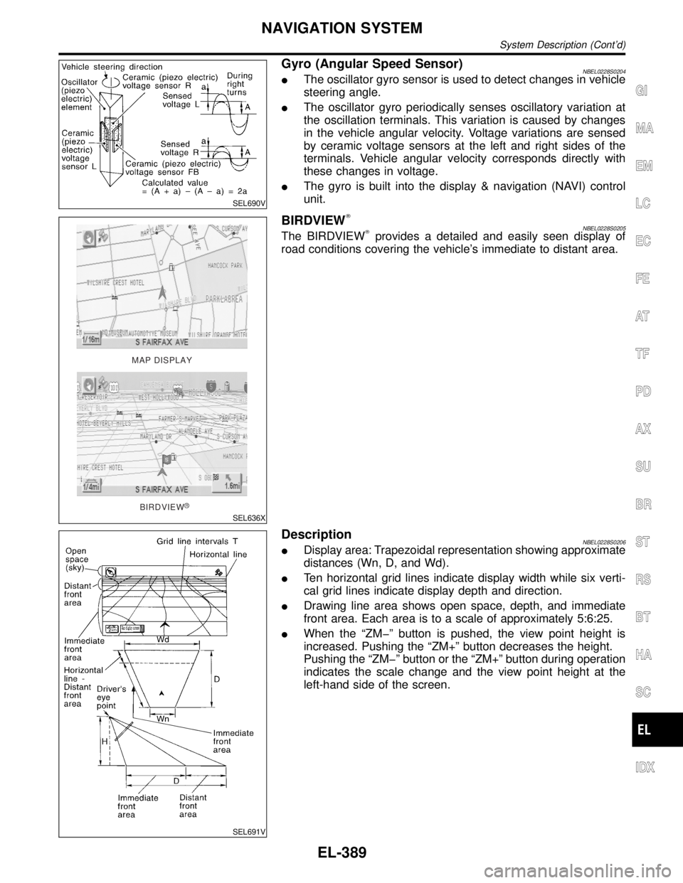
Gyro (Angular Speed Sensor)NBEL0228S0204IThe oscillator gyro sensor is used to detect changes in vehicle
steering angle.
IThe oscillator gyro periodically senses oscillatory variation at
the oscillation terminals. This variation is caused by changes
in the vehicle angular velocity. Voltage variations are sensed
by ceramic voltage sensors at the left and right sides of the
terminals. Vehicle angular velocity corresponds directly with
these changes in voltage.
IThe gyro is built into the display & navigation (NAVI) control
unit.
MAP DISPLAY
BIRDVIEW
R
SEL636X
BIRDVIEWTNBEL0228S0205The BIRDVIEWTprovides a detailed and easily seen display of
road conditions covering the vehicle's immediate to distant area.
SEL691V
DescriptionNBEL0228S0206IDisplay area: Trapezoidal representation showing approximate
distances (Wn, D, and Wd).
ITen horizontal grid lines indicate display width while six verti-
cal grid lines indicate display depth and direction.
IDrawing line area shows open space, depth, and immediate
front area. Each area is to a scale of approximately 5:6:25.
IWhen the ªZMþº button is pushed, the view point height is
increased. Pushing the ªZM+º button decreases the height.
Pushing the ªZMþº button or the ªZM+º button during operation
indicates the scale change and the view point height at the
left-hand side of the screen.
GI
MA
EM
LC
EC
FE
AT
TF
PD
AX
SU
BR
ST
RS
BT
HA
SC
IDX
NAVIGATION SYSTEM
System Description (Cont'd)
EL-389
Page 1576 of 2395

Display with Pushed ªDESTº Switch=NBEL0228S0302
SEL581X
The function of each touch switch is as follows:
Icon Description
Address Book Favorite place can be saved to memory.
The destination can be selected from the memory.
Address/Street The destination can be searched from the address.
Point of Interest (POI) The destination of favorite facility can be searched.
Previous Dest. The previous ten destinations stored in memory are
displayed.
Intersection The destination from the intersection name can be
retrieved.
City The destination can be searched from city name.
Map The destination can be searched from the map.
GI
MA
EM
LC
EC
FE
AT
TF
PD
AX
SU
BR
ST
RS
BT
HA
SC
IDX
NAVIGATION SYSTEM
System Description (Cont'd)
EL-391
Page 1578 of 2395

SchematicNBEL0229
MEL268M
GI
MA
EM
LC
EC
FE
AT
TF
PD
AX
SU
BR
ST
RS
BT
HA
SC
IDX
NAVIGATION SYSTEM
Schematic
EL-393
Page 1580 of 2395

MEL269M
GI
MA
EM
LC
EC
FE
AT
TF
PD
AX
SU
BR
ST
RS
BT
HA
SC
IDX
NAVIGATION SYSTEM
Wiring Diagram Ð NAVI Ð (Cont'd)
EL-395
Page 1582 of 2395

Self-diagnosis ModeNBEL0231APPLICATION ITEMSNBEL0231S01
Mode DescriptionReference
page
Self DiagnosisSelf-diagnosis for display & NAVI control unit, CD-ROM
and GPS antenna connection.EL-398
Confirmation/
adjustmentDisplay Diagnosis Color and gray gradation of display can be checked in
this mode.EL-406
Diagnostic Signals from the Car Several input signals to display & NAVI control unit, can
be monitored in this mode.EL-404
NavigationCheck the map CD-
ROM versionThe version (parts number) of inserted CD-ROM can be
checked in this mode.EL-405
Error history Diagnosis results previously stored in the memory
(before turning ignition switch ON) are displayed in this
mode. Time and location when/where the errors
occurred are also displayed.EL-400
Longitude & Latitude Display the map. Use the joystick to adjust position. Lon-
gitude and latitude will be displayed.EL-407
Adjust the angle Turning angle of the vehicle on the display can be
adjusted in this mode.EL-408
Speed CalibrationUnder ordinary conditions, the navigation system dis-
tance measuring function will automatically compensate
for minute decreases in wheel and tire diameter caused
by tire wear or low pressure. Speed calibration immedi-
ately restores system accuracy in cases such as when
distance calibration is needed because of the use of tire
chains in inclement weather.EL-409
Initialize Location This mode is for initializing the current location. Use
when the vehicle is transported a long distance on a
trailer, etc.EL-433
SEL583X
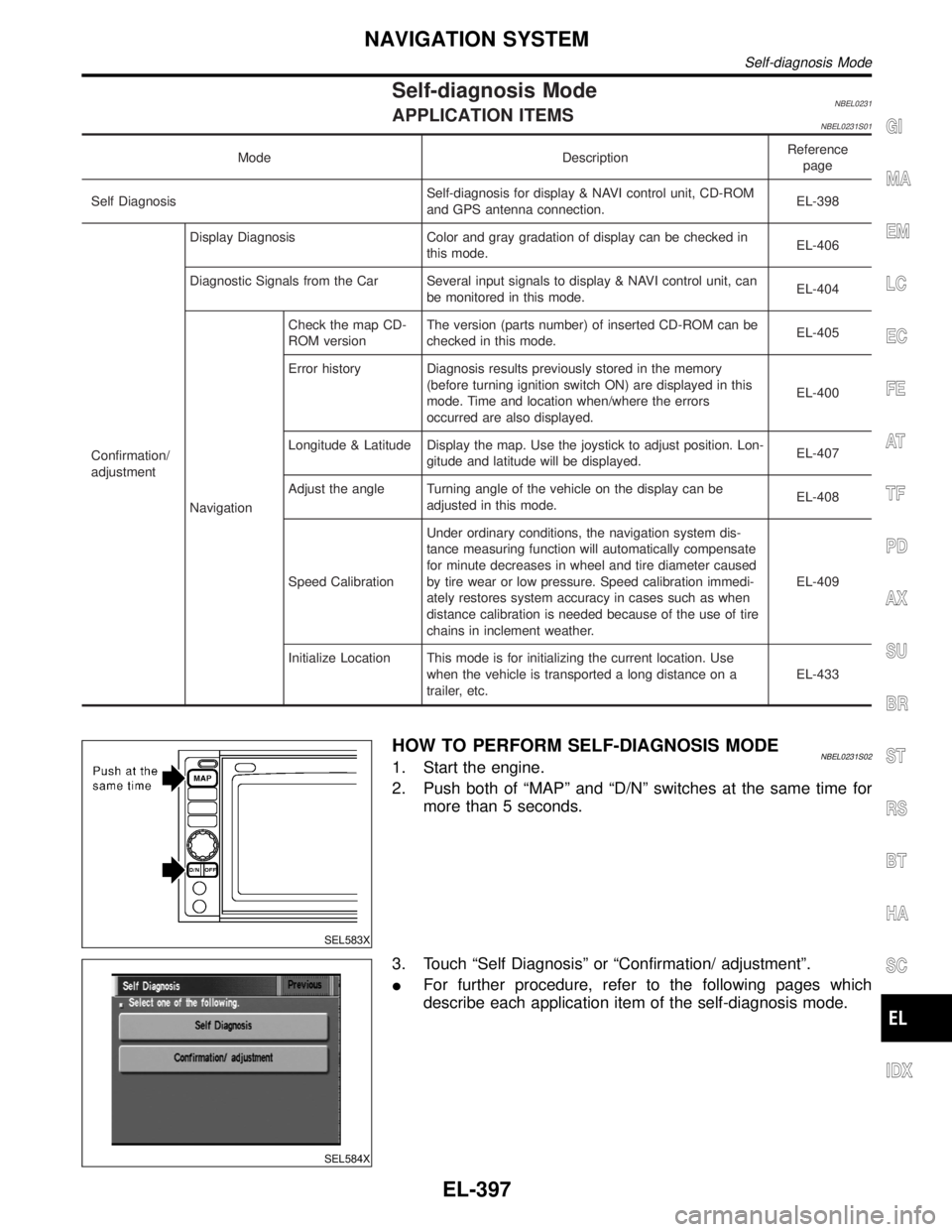
HOW TO PERFORM SELF-DIAGNOSIS MODENBEL0231S021. Start the engine.
2. Push both of ªMAPº and ªD/Nº switches at the same time for
more than 5 seconds.
SEL584X
3. Touch ªSelf Diagnosisº or ªConfirmation/ adjustmentº.
IFor further procedure, refer to the following pages which
describe each application item of the self-diagnosis mode.
GI
MA
EM
LC
EC
FE
AT
TF
PD
AX
SU
BR
ST
RS
BT
HA
SC
IDX
NAVIGATION SYSTEM
Self-diagnosis Mode
EL-397
Page 1584 of 2395

SELF-DIAGNOSIS RESULTS=NBEL0231S03
Diagnosed
itemDisplayed
colorDetailed result DescriptionDiagnoses/service procedure
Recheck system at each check or
replacement (When malfunction is
eliminated, further repair work is
not required.)
ªGPS
Antennaº
(GPS
antenna con-
nection)Green ÐGPS antenna is connected to dis-
play & NAVI control unit correctly.Ð
YellowConnection to the follow-
ing unit is abnormal. See
the Service Manual for
further diagnosis.GPS antenna connection error is
detected.1. Check GPS antenna feeder cable
connection at display & NAVI
control unit.
2. Visually check GPS antenna
feeder cable. If NG, replace GPS
antenna assembly.
3. Replace GPS antenna.
ªNavigationº
(Display &
NAVI control
unit)Green Ð No failure is detected. Ð
Red [*** is abnormal.]Display & NAVI control unit is mal-
functioning.Replace display & NAVI control unit.
GraySelf-diagnosis for CD-
ROM DRIVER of DISP &
NAVI was not conducted
due to no insertion of
CD-ROM.Any CD-ROM is not inserted or dis-
play & NAVI control unit is malfunc-
tioning.1. Confirm that map CD-ROM is not
inserted into display & NAVI con-
trol unit.
2. Replace display & NAVI control
unit.
YellowCD-ROM or CD-ROM
DRIVER of DISP & NAVI
is abnormal. See the
Service Manual for fur-
ther diagnosis.Display & NAVI control unit judges
that inserted CD-ROM is malfunc-
tioning.
Map CD-ROM or CD-ROM driver of
the unit is malfunctioning.1. Confirm the disk is installed cor-
rectly (not up side down.)
2. Perform ªCD-ROM VERSION
CHECKº in EL-405 to confirm
whether correct CD-ROM is
inserted or not.
3. Check the disk surface. Are there
any scratches, abrasions or pits
on the surface?
4. Replace the CD-ROM.
5. Replace display & NAVI control
unit. CD-ROM is abnormal.
Please check the disc.Inserted map CD-ROM can not be
read.
Map CD-ROM or CD-ROM driver of
the unit is malfunctioning.
Connection to the follow-
ing unit is abnormal. See
the Service Manual for
further diagnosis.GPS antenna connection error is
detected.1. Check GPS antenna feeder cable
connection at display & NAVI
control unit.
2. Visually check GPS antenna
feeder cable. If NG, replace GPS
antenna assembly.
3. Replace GPS antenna.
GI
MA
EM
LC
EC
FE
AT
TF
PD
AX
SU
BR
ST
RS
BT
HA
SC
IDX
NAVIGATION SYSTEM
Self-diagnosis Mode (Cont'd)
EL-399