IDX INFINITI QX4 2001 Factory Service Manual
[x] Cancel search | Manufacturer: INFINITI, Model Year: 2001, Model line: QX4, Model: INFINITI QX4 2001Pages: 2395, PDF Size: 43.2 MB
Page 1646 of 2395

Parts Requiring Angular TighteningNBEM0001IUse an angle wrench for the final tightening of the following
engine parts:
a) Cylinder head bolts
b) Main bearing cap bolts
c) Connecting rod cap bolts
d) Crankshaft pulley bolt
IDo not use a torque value for final tightening.
IThe torque value for these parts are for a preliminary step.
IEnsure thread and seat surfaces are clean and coated with
engine oil.
SEM164F
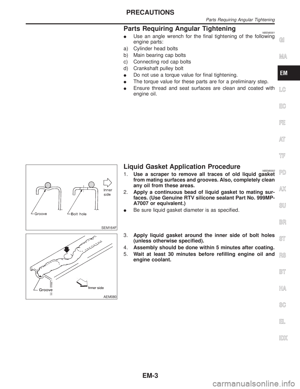
Liquid Gasket Application ProcedureNBEM00021.Use a scraper to remove all traces of old liquid gasket
from mating surfaces and grooves. Also, completely clean
any oil from these areas.
2.Apply a continuous bead of liquid gasket to mating sur-
faces. (Use Genuine RTV silicone sealant Part No. 999MP-
A7007 or equivalent.)
IBe sure liquid gasket diameter is as specified.
AEM080
3.Apply liquid gasket around the inner side of bolt holes
(unless otherwise specified).
4.Assembly should be done within 5 minutes after coating.
5.Wait at least 30 minutes before refilling engine oil and
engine coolant.
GI
MA
LC
EC
FE
AT
TF
PD
AX
SU
BR
ST
RS
BT
HA
SC
EL
IDX
PRECAUTIONS
Parts Requiring Angular Tightening
EM-3
Page 1648 of 2395

Tool number
(Kent-Moore No.)
Tool nameDescription
(J39386)
Valve oil seal drift
NT024
Installing valve oil seal
KV101151S0
(J38972)
Lifter stopper set
1 KV10115110
(J38972-1)
Camshaft pliers
2 KV10115120
(J38972-2)
Lifter stopper
NT041
Changing shims
EM03470000
(J8037)
Piston ring compressor
NT044
Installing piston assembly into cylinder bore
ST16610001
(J23907)
Pilot bushing puller
NT045
Removing crankshaft pilot bushing
KV101111 0 0
(J37228)
Seal cutter
NT046
Removing steel oil pan and rear timing chain case
WS39930000
(Ð)
Tube presser
NT052
Pressing the tube of liquid gasket
KV10112100
(BT8653-A)
Angle wrench
NT014
Tightening bolts for bearing cap, cylinder head, etc.
GI
MA
LC
EC
FE
AT
TF
PD
AX
SU
BR
ST
RS
BT
HA
SC
EL
IDX
PREPARATION
Special Service Tools (Cont'd)
EM-5
Page 1650 of 2395

Tool number
(Kent-Moore No.)
Tool nameDescription
Valve guide reamer
NT016
Reaming valve guide 1 or hole for oversize valve
guide 2
Intake & Exhaust:
d
1= 6.0 mm (0.236 in) dia.
d
2= 10.2 mm (0.402 in) dia.
(J-43897-18)
(J-43897-12)
Oxygen sensor thread
cleaner
AEM488
Reconditioning the exhaust system threads before
installing a new oxygen sensor (Use with anti-seize
lubricant shown below.)
a = J-43897-18 (18 mm dia.) for zirconia oxygen
sensor
b = J-43897-12 (12 mm dia.) for titania oxygen
sensor
Anti-seize lubricant
(Permatex 133AR or
equivalent meeting MIL
specification MIL-A-
907)
AEM489
Lubricating oxygen sensor thread cleaning tool
when reconditioning exhaust system threads
GI
MA
LC
EC
FE
AT
TF
PD
AX
SU
BR
ST
RS
BT
HA
SC
EL
IDX
PREPARATION
Commercial Service Tools (Cont'd)
EM-7
Page 1652 of 2395

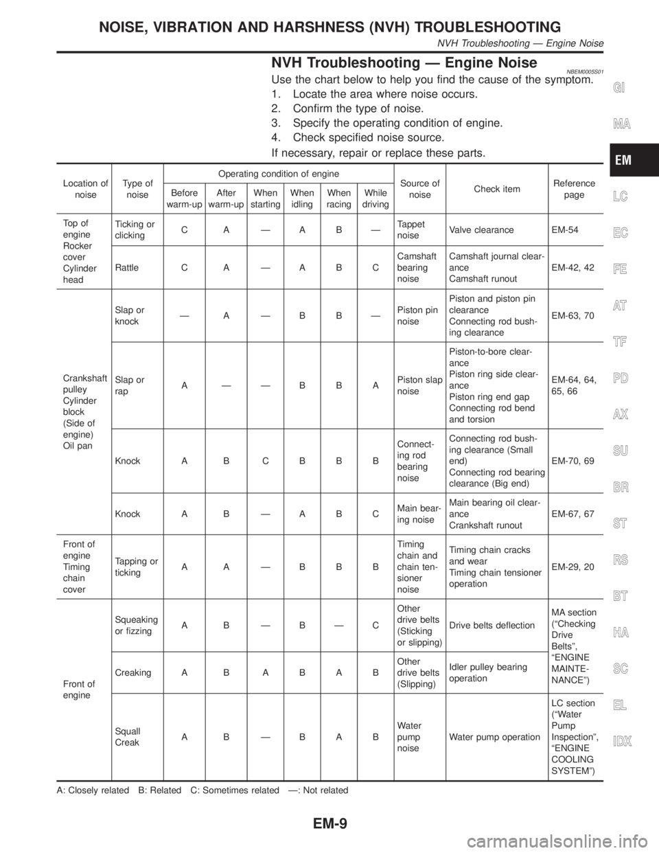
NVH Troubleshooting Ð Engine NoiseNBEM0005S01Use the chart below to help you find the cause of the symptom.
1. Locate the area where noise occurs.
2. Confirm the type of noise.
3. Specify the operating condition of engine.
4. Check specified noise source.
If necessary, repair or replace these parts.
Location of
noiseType of
noiseOperating condition of engine
Source of
noiseCheck itemReference
page Before
warm-upAfter
warm-upWhen
startingWhen
idlingWhen
racingWhile
driving
To p o f
engine
Rocker
cover
Cylinder
headTicking or
clickingC A ÐA BÐTappet
noiseValve clearance EM-54
Rattle C A Ð A B CCamshaft
bearing
noiseCamshaft journal clear-
ance
Camshaft runoutEM-42, 42
Crankshaft
pulley
Cylinder
block
(Side of
engine)
Oil panSlap or
knockÐ A ÐB BÐPiston pin
noisePiston and piston pin
clearance
Connecting rod bush-
ing clearanceEM-63, 70
Slap or
rapA ÐÐBBAPiston slap
noisePiston-to-bore clear-
ance
Piston ring side clear-
ance
Piston ring end gap
Connecting rod bend
and torsionEM-64, 64,
65, 66
Knock A B C B B BConnect-
ing rod
bearing
noiseConnecting rod bush-
ing clearance (Small
end)
Connecting rod bearing
clearance (Big end)EM-70, 69
Knock A B Ð A B CMain bear-
ing noiseMain bearing oil clear-
ance
Crankshaft runoutEM-67, 67
Front of
engine
Timing
chain
coverTapping or
tickingA A ÐBBBTiming
chain and
chain ten-
sioner
noiseTiming chain cracks
and wear
Timing chain tensioner
operationEM-29, 20
Front of
engineSqueaking
or fizzingA B ÐBÐCOther
drive belts
(Sticking
or slipping)Drive belts deflectionMA section
(ªChecking
Drive
Beltsº,
ªENGINE
MAINTE-
NANCEº) Creaking A BABABOther
drive belts
(Slipping)Idler pulley bearing
operation
Squall
CreakA B ÐBABWater
pump
noiseWater pump operationLC section
(ªWater
Pump
Inspectionº,
ªENGINE
COOLING
SYSTEMº)
A: Closely related B: Related C: Sometimes related Ð: Not related
GI
MA
LC
EC
FE
AT
TF
PD
AX
SU
BR
ST
RS
BT
HA
SC
EL
IDX
NOISE, VIBRATION AND HARSHNESS (NVH) TROUBLESHOOTING
NVH Troubleshooting Ð Engine Noise
EM-9
Page 1654 of 2395

SEM484GA
1. Heated oxygen sensor 1 (front)
(bank 1)
2. Heated oxygen sensor 1 (front)
(bank 2)
3. TWC (manifold)4. Thermostat with water inlet
5. Exhaust manifold
6. Thermal transmitter
7. Engine coolant temperature8. Water control valve
9. Water outlet housing
10. Cylinder block water outlet
GI
MA
LC
EC
FE
AT
TF
PD
AX
SU
BR
ST
RS
BT
HA
SC
EL
IDX
OUTER COMPONENT PARTS
Removal and Installation (Cont'd)
EM-11
Page 1656 of 2395

SEM477G
Lower Intake Manifold CollectorNBEM0006S0108Tighten bolts and nuts to 18 to 21 N´m (1.8 to 2.2 kg-m, 13 to 15
ft-lb) in numerical order shown in the figure.
SEM478G
SEM479G
Exhaust ManifoldNBEM0006S0109Tighten nuts to 28 to 32 N´m (2.9 to 3.3 kg-m, 21 to 24 ft-lb) in
numerical order shown in the figure.
SEM607G
TWC (Manifold)NBEM0006S0110IAlign the mating mark as shown for locating exhaust flange.
SEM609G
IInstall washer and mesh washer as shown.
GI
MA
LC
EC
FE
AT
TF
PD
AX
SU
BR
ST
RS
BT
HA
SC
EL
IDX
OUTER COMPONENT PARTS
Removal and Installation (Cont'd)
EM-13
Page 1658 of 2395

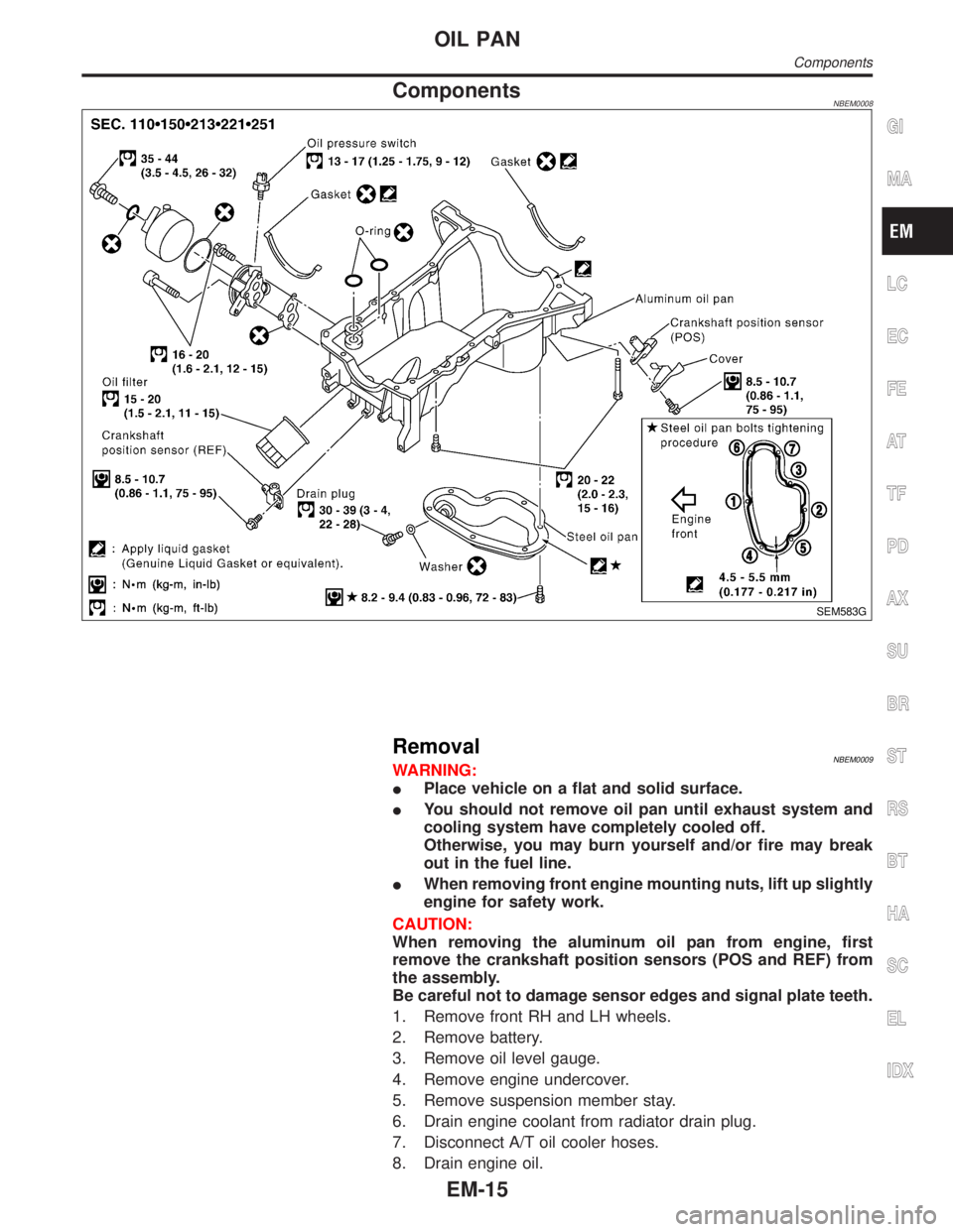
ComponentsNBEM0008
SEM583G
RemovalNBEM0009WARNING:
IPlace vehicle on a flat and solid surface.
IYou should not remove oil pan until exhaust system and
cooling system have completely cooled off.
Otherwise, you may burn yourself and/or fire may break
out in the fuel line.
IWhen removing front engine mounting nuts, lift up slightly
engine for safety work.
CAUTION:
When removing the aluminum oil pan from engine, first
remove the crankshaft position sensors (POS and REF) from
the assembly.
Be careful not to damage sensor edges and signal plate teeth.
1. Remove front RH and LH wheels.
2. Remove battery.
3. Remove oil level gauge.
4. Remove engine undercover.
5. Remove suspension member stay.
6. Drain engine coolant from radiator drain plug.
7. Disconnect A/T oil cooler hoses.
8. Drain engine oil.
GI
MA
LC
EC
FE
AT
TF
PD
AX
SU
BR
ST
RS
BT
HA
SC
EL
IDX
OIL PAN
Components
EM-15
Page 1660 of 2395

SEM529G
SEM530G
23. Remove front suspension member bolts.
24. Lower the transmission jack carefully to secure clearance
between the oil pan and suspension member.
25. Remove A/T oil cooler tube.
26. Remove water hose and tube.
SEM469G
27. Remove the four engine-to-transmission bolts.
SEM463G
28. Remove aluminum oil pan bolts in numerical order.
SEM365E
29. Remove aluminum oil pan.
a. Insert tool between aluminum oil pan and cylinder block.
IBe careful not to damage aluminum mating surface.
IDo not insert screwdriver, or oil pan flange will be
deformed.
b. Slide tool by tapping its side with a hammer.
GI
MA
LC
EC
FE
AT
TF
PD
AX
SU
BR
ST
RS
BT
HA
SC
EL
IDX
OIL PAN
Removal (Cont'd)
EM-17
Page 1662 of 2395

SEM159F
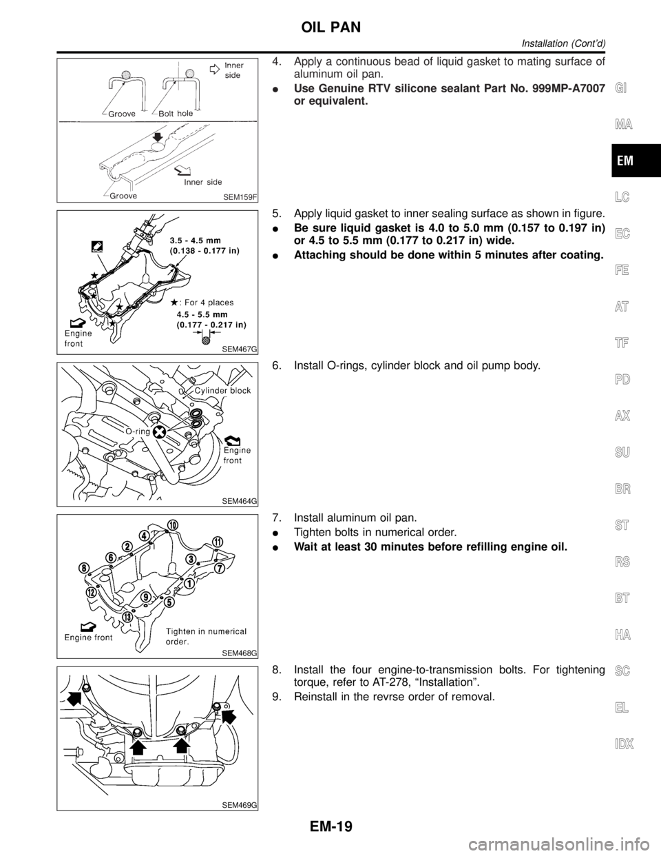
4. Apply a continuous bead of liquid gasket to mating surface of
aluminum oil pan.
IUse Genuine RTV silicone sealant Part No. 999MP-A7007
or equivalent.
SEM467G
5. Apply liquid gasket to inner sealing surface as shown in figure.
IBe sure liquid gasket is 4.0 to 5.0 mm (0.157 to 0.197 in)
or 4.5 to 5.5 mm (0.177 to 0.217 in) wide.
IAttaching should be done within 5 minutes after coating.
SEM464G
6. Install O-rings, cylinder block and oil pump body.
SEM468G
7. Install aluminum oil pan.
ITighten bolts in numerical order.
IWait at least 30 minutes before refilling engine oil.
SEM469G
8. Install the four engine-to-transmission bolts. For tightening
torque, refer to AT-278, ªInstallationº.
9. Reinstall in the revrse order of removal.
GI
MA
LC
EC
FE
AT
TF
PD
AX
SU
BR
ST
RS
BT
HA
SC
EL
IDX
OIL PAN
Installation (Cont'd)
EM-19
Page 1664 of 2395

POSITION FOR APPLYING LIQUID GASKET=NBEM0011S01Refer to ªInstallationº in ªOIL PANº, EM-18.
IBefore installation, wipe off the protruding sealant.
GI
MA
LC
EC
FE
AT
TF
PD
AX
SU
BR
ST
RS
BT
HA
SC
EL
IDX
TIMING CHAIN
Components (Cont'd)
EM-21