coolant temperature INFINITI QX4 2001 Factory Manual PDF
[x] Cancel search | Manufacturer: INFINITI, Model Year: 2001, Model line: QX4, Model: INFINITI QX4 2001Pages: 2395, PDF Size: 43.2 MB
Page 1841 of 2395

TERMINAL
NO.ITEM CONDITIONVoltage
V
6 Intake door position switch
Intake door positionRECIRCULATION Approximately 4.6
FRESH or 20% FRESH Approximately 0
7Multiplex communication sig-
nal
(AMP,NAVI)ÐÐ
8Multiplex communication sig-
nal
(NAVI,AMP)ÐÐ
9 Sensor ground
Ð Approximately 0
10 Sunload sensor Ð Ð
11 Thermal transmitter
Engine coolant
temperatureApproximately 30ÉC (86ÉF) Approximately 9.4
Approximately 55ÉC (131ÉF) Approximately 6.5
Approximately 100ÉC
(212ÉF)Approximately 2.4
Approximately 110ÉC
(230ÉF)Approximately 1.9
14 A/C LAN signal Ð Approximately 5.5
17 ECM signalCompressor: ON Approximately 0
Compressor: OFF Approximately 4.6
18 Intake door position switch Intake door positionFRESH Approximately 4.6
RECIRCULATION or 20%
FRESHApproximately 0
19 Intake door position switch Intake door position20% FRESH Approximately 4.6
RECIRCULATION or
FRESHApproximately 0
20Multiplex communication sig-
nal (CLK)ÐÐ
21 Power supply for door motor
Ð Approximately 12
22 Compressor ON signalCompressor: ON Approximately 0
Compressor: OFF Approximately 4.6
24 Power supply for BAT Ð BATTERY VOLTAGE
TROUBLE DIAGNOSES
Auto Amp. Terminals and Reference Value (Cont'd)
HA-42
Page 1896 of 2395

SYSTEM DESCRIPTION=NBHA0062Component partsNBHA0062S01Fan speed control system components are:
1) Auto amp.
2) Fan control amp.
3) A/C LAN system (PBR built-in mode door motor and air mix door motor)
4) In-vehicle sensor
5) Ambient sensor
6) Sunload sensor
7) Intake sensor
System OperationNBHA0062S02
SHA006FF
Automatic ModeNBHA0062S03In the automatic mode, the blower motor speed is calculated by the automatic amplifier based on inputs from
the PBR, in-vehicle sensor, sunload sensor, intake sensor and ambient sensor. The blower motor applied
voltage ranges from approximately 5 volts (lowest speed) to 12 volts (highest speed).
The control blower speed (in the range of 5 to 12V), the automatic amplifier supplies a gate voltage to the fan
control amplifier. Based on this voltage, the fan control amplifier controls the voltage supplied to the blower
motor.
Starting Fan Speed ControlNBHA0062S04Start Up From ªCOLD SOAKº Condition (Automatic mode)NBHA0062S0401In a cold start up condition where the engine coolant temperature is below 50ÉC (122ÉF), the blower will not
operate for a short period of time (up to 126 seconds). The exact start delay time varies depending on the
ambient and engine coolant temperature.
In the most extreme case (very low ambient) the blower starting delay will be 126 seconds as described above.
After this delay, the blower will operate at low speed until the engine coolant temperature rises above 55ÉC
(131ÉF), at which time the blower speed will increase to the objective speed.
Start Up From Normal or ªHOT SOAKº Condition (Automatic mode)
NBHA0062S0402The blower will begin operation momentarily after the AUTO button is pushed. The blower speed will gradu-
ally rise to the objective speed over a time period of 3 seconds or less (actual time depends on the objective
blower speed).
GI
MA
EM
LC
EC
FE
AT
TF
PD
AX
SU
BR
ST
RS
BT
SC
EL
IDX
TROUBLE DIAGNOSES
Blower Motor (Cont'd)
HA-97
Page 1963 of 2395

E
ECM input/output signal ...............................EC-127
ECTS - Wiring diagram ........................EC-171, 189
Electric sun roof ............................................EL-173
Electrical diagnoses.........................................GI-24
Electrical ignition system ................................EC-30
Electrical unit ................................................Foldout
Electrical units location .................................EL-436
Engine compartment .......................................BT-58
Engine control circuit diagram........................EC-24
Engine control component parts
location .......................................................EC-20
Engine control module (ECM) ......................EC-444
Engine control system diagram and
chart ............................................................EC-25
Engine coolant temperature sensor
(ECTS) ..............................................EC-169, 187
Engine fail-safe system ................................EC-117
Engine oil filter replacement ..........................MA-18
Engine oil precautions .......................................GI-8
Engine oil replacement ..................................MA-18
Engine outer component parts ......................EM-10
Engine removal ..............................................EM-57
Engine room - See Engine
compartment................................................BT-58
Engine serial number ......................................GI-43
EVAP canister.................................................EC-33
EVAP canister purge volume control
solenoid valve.............................EC-32, 367, 541
EVAP canister vent control
valve .........................................EC-374, 553, 573
EVAP control system (small leak)
diagnosis ..................................EC-352, 394, 526
EVAP control system pressure sensor.........EC-381
EVAP control system purge flow moni-
toring diagnosis.........................................EC-561
EVAP vapor lines inspection ..........................MA-20
Evaporative emission (EVAP) system ............EC-32
Exhaust system ................................................FE-8
Exhaust system inspection ............................MA-21
Exterior ............................................................BT-35
F
4LO indicator lamp........................................TF-104
4WD shift indicator lamp.................................TF-98
4WD shift switch ............................................TF-111
4WD solenoid valve.......................................TF-111
4WD warning lamp .........................................TF-13
Fan control amp. ............................................HA-98
F/FOG - Wiring diagram .................................EL-72
Final drive disassembly ..................................PD-43
Final drive pre-inspection ...............................PD-43
Final drive removal and installation ...............PD-43
Finisher, interior - See Trim ............................BT-28
F/LID - Wiring diagram .................................EL-180
Fluid temperature sensor (A/T) .....................AT-110Fluids ..............................................................MA-11
Flywheel runout..............................................EM-70
FO2H-L - Wiring diagram .............................EC-243
FO2H-R - Wiring diagram ............................EC-242
Fog lamp, front................................................EL-70
Fog lamp, front, removal and
installation ...................................................BT-12
Forward clutch ...............................................AT-320
F/PUMP - Wiring diagram ............................EC-627
Freeze frame data ..........................................EC-60
FRO2LH - Wiring diagram ...........EC-197, 223, 235
FRO2RH - Wiring diagram...........EC-196, 222, 234
Front axle..........................................................AX-2
Front bumper ..................................................BT-12
Front case (Transfer) ....................................TF-133
Front combination lamp removal and
installation ...................................................BT-12
Front disc brake .............................................BR-22
Front door .......................................................BT-18
Front drive shaft (Transfer) ...........................TF-125
Front final drive disassembly (4WD) ..............PD-18
Front final drive pre-inspection (4WD) ...........PD-18
Front final drive removal and installa-
tion (4WD)...................................................PD-18
Front fog lamp.................................................EL-70
Front fog lamp removal and installation .........BT-12
Front heated oxygen sensor (HO2S)
(Left bank) ................EC-192, 202, 210, 218, 231
Front heated oxygen sensor (HO2S)
(Right bank) .............EC-192, 202, 210, 218, 231
Front heated oxygen sensor heater
(Left bank).................................................EC-240
Front heated oxygen sensor heater
(Right bank) ..............................................EC-240
Front revolution sensor (Transfer) ................TF-112
Front seat ........................................................BT-41
Front seat belt ..................................................RS-4
Front suspension ..............................................SU-2
Front washer .................................................EL-136
Front wiper ....................................................EL-136
Fuel cut control (at no load & high
engine speed) .............................................EC-32
Fuel filler lid.....................................................BT-15
Fuel filter replacement ...................................MA-16
Fuel gauge ......................................................EL-94
Fuel injection system (Left bank) .........EC-294, 302
Fuel injection system (Right bank) ......EC-294, 302
Fuel lid opener, electric.................................EL-180
Fuel line inspection ........................................MA-16
Fuel precautions ................................................GI-8
Fuel pressure check .......................................EC-39
Fuel pressure regulator ..................................EC-40
Fuel pressure release ....................................EC-39
Fuel pump ....................................................EC-625
Fuel system ......................................................FE-4
Fuel tank temperature sensor ......................EC-309
Fuel tank vacuum relief valve ........................EC-33
FUELLH - Wiring diagram....................EC-297, 305
FUELRH - Wiring diagram ...................EC-296, 304
Fuse ................................................................EL-16
Fuse block ....................................................Foldout
ALPHABETICAL INDEX
IDX-4
Page 1985 of 2395

Thermostat
REMOVAL AND INSTALLATIONNBLC0021
SLC329B
SLC962AA
1. Remove under cover.
2. Remove suspension member stay.
3. Drain coolant from radiator.
4. Remove drive belts.
5. Remove water drain plug on water pump side of cylinder block.
6. Disconnect lower radiator hose.
7. Remove water inlet and thermostat assembly.
IDo not disassemble water inlet and thermostat. Replace
them as a unit, if necessary.
SLC948A
8. Install thermostat with jiggle valve facing upward.
IAfter installation, run engine for a few minutes, and check
for leaks.
IBe careful not to spill coolant over engine compartment.
Use a rag to absorb coolant.
9. Reinstall any removed parts in reverse order of removal.
SLC949A
INSPECTIONNBLC00221. Check valve seating condition at ordinary room temperatures.
It should seat tightly.
2. Check valve opening temperature and maximum valve lift.
Standard
Valve opening temperature 76.5ÉC (170ÉF)
Valve lift More than 8.6 mm/90ÉC
(0.339 in/194ÉF)
ENGINE COOLING SYSTEM
Thermostat
LC-16
Page 1986 of 2395

3. Then check if valve closes at 5ÉC (9ÉF) below valve opening
temperature.
Water Control Valve
REMOVAL AND INSTALLATIONNBLC0032
SLC330B
1. Water outlet housing
2. Water control valve
3. Water outlet4. Water hose
5. Cylinder block water outlet
6. Thermal transmitter7. Engine coolant temperature sen-
sor
1. Release fuel pressure.
Refer to EC-39, ªFuel Pressure Releaseº.
2. Remove under cover.
3. Remove suspension member stay.
4. Drain coolant from radiator.
5. Remove engine cover.
6. Remove air duct with air cleaner assembly.
7. Disconnect wires, hoses, harness and so on.
8. Remove upper intake manifold corrector.
9. Remove intake manifold corrector support bolts.
10. Remove lower intake manifold corrector.
11. Disconnect injector harness connectors.
12. Remove injector tube.
13. Remove intake manifold.
14. Remove water outlet housing and water control valve.
GI
MA
EM
EC
FE
AT
TF
PD
AX
SU
BR
ST
RS
BT
HA
SC
EL
IDX
ENGINE COOLING SYSTEM
Thermostat (Cont'd)
LC-17
Page 1987 of 2395

SLC334B
15. Install water control valve and water outlet housing.
a. Install gum ring to thermostat.
b. Point the arrow on the upper surface of the valve to the front
of the engine, and also be sure to install the protrusions and
the valve stopper so that they are aligned in a straight line.
16. Reinstall any removed parts in reverse order of removal.
IWhen installing intake manifold, injector tube and intake
manifold collectors, refer to EM-12, ªTIGHTENING PROCE-
DURESº.
IAfter installation, run engine for a few minutes, and check
for leaks.
IBe careful not to spill coolant over engine compartment.
Use a rag to absorb coolant.
SLC252B
INSPECTIONNBLC00331. Check valve seating condition at ordinary room temperatures.
It should seat tightly.
2. Check valve opening temperature and maximum valve lift.
Standard
Valve opening temperature 95ÉC (203ÉF)
Valve lift More than 8.0 mm/108ÉC
(0.315 in/226ÉF)
3. Then check if valve closes at 5ÉC (9ÉF) below valve opening
temperature.
ENGINE COOLING SYSTEM
Water Control Valve (Cont'd)
LC-18
Page 2006 of 2395

NBMA0005
Fluids and LubricantsNBMA0005S01
Capacity (Approximate)
Recommended Fluids/Lubricants
US measure Imp measure Liter
Engine oilDrain and
refillWith oil filter 5-1/4 qt 4-3/8 qt 5.0
IAPI Certification Mark*1
IAPI grade SG/SH, Energy Conserv-
ingI&IIorAPIgrade SJ, Energy
Conserving*1
IILSAC grade GF-I & GF-II*1 Without oil
filter5-1/8 qt 4-1/4 qt 4.8
Dry engine
(Engine overhaul)7-1/4 qt 6 qt 6.8
Cooling system (With reservoir) 9-3/4 qt 8-1/8 qt 9.2Genuine Nissan anti-freeze coolant or
equivalent
All-mode 4WD transfer fluid 3-1/8 qt 2-5/8 qt 3.0Nissan Matic ªDº (Continental U.S. and
Alaska) or Canada NISSAN Automatic
Transmission Fluid*2
Differential
carrier gear
oilFront (4WD) 3-7/8 pt 3-1/4 pt 1.85Standard differential gear: API GL-5*1
Limited-slip differential (LSD) gear:
Use only LSD gear oil API GL-5 and
SAE 80W-90*5 approved for Nissan
LSD*6. Rear 5-7/8 pt 4-7/8 pt 2.8
Automatic transmission fluid2WD
9 qt 7-1/2 qt 8.5Nissan Matic ªDº (Continental U.S. and
Alaska) or Canada NISSAN Automatic
Transmission Fluid*3 4WD
Power steering fluid Ð Ð Ð Genuine NISSAN PSF II or equivalent*7
Brake fluid Ð Ð ÐGenuine Nissan Brake Fluid*4 or
equivalent DOT 3 (U.S. FMVSS No.
116)
Propeller shaft grease Ð Ð ÐNLGI No. 2 (Molybdenum disulphide
lithium soap base)
Multi-purpose grease Ð Ð Ð NLGI No. 2 (Lithium soap base)
*1: For further details, see ªSAE Viscosity Numberº.
*2: Outside the continental United States and Alaska contact an authorized INFINITI dealership for more information regarding suitable
fluids, including recommended brand(s) of DEXRON
TMIII/MERCONTMAutomatic Transmission Fluid.
*3: DEXRONTMIII/MERCONTMor equivalent may also be used. Outside the continental United States and Alaska contact an autho-
rized INFINITI dealership for more information regarding suitable fluids, including recommended brand(s) of DEXRONTMIII/MERCONTM
Automatic Transmission Fluid.
*4: Available in mainland U.S.A. through your INFINITI dealer.
*5: SAE 90 is acceptable in ambient temperatures above þ18ÉC (0ÉF).
*6: Contact an INFINITI dealer for a list of approved oils.
*7: Genuine NISSAN PSF, Canada NISSAN Automatic Transmission Fluid, DEXRON
TMIII/MERCONTMor equivalent ATF may also be
used.
GI
EM
LC
EC
FE
AT
TF
PD
AX
SU
BR
ST
RS
BT
HA
SC
EL
IDX
RECOMMENDED FLUIDS AND LUBRICANTS
Fluids and Lubricants
MA-11
Page 2007 of 2395

MMA117AA
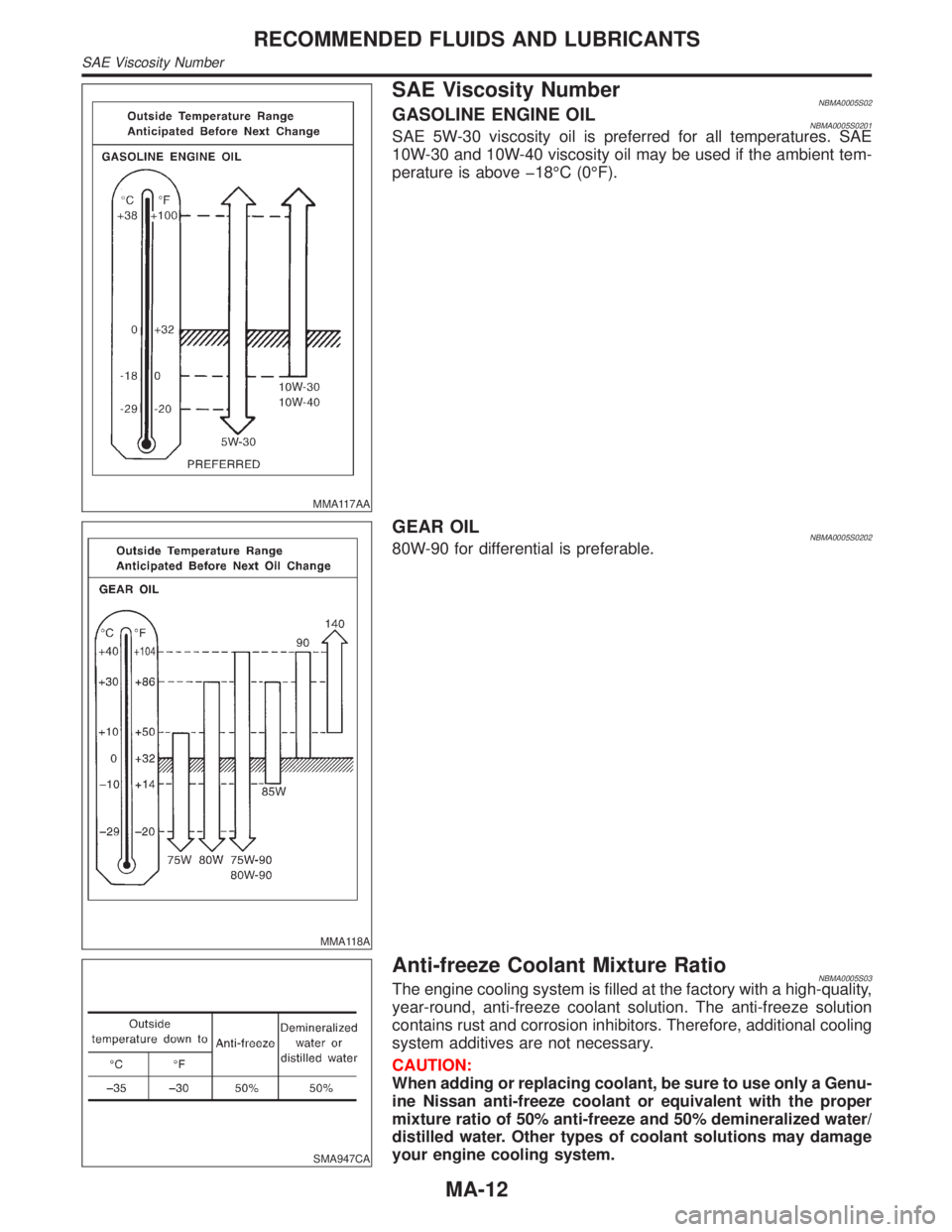
SAE Viscosity NumberNBMA0005S02GASOLINE ENGINE OILNBMA0005S0201SAE 5W-30 viscosity oil is preferred for all temperatures. SAE
10W-30 and 10W-40 viscosity oil may be used if the ambient tem-
perature is above þ18ÉC (0ÉF).
MMA118A
GEAR OILNBMA0005S020280W-90 for differential is preferable.
SMA947CA
Anti-freeze Coolant Mixture RatioNBMA0005S03The engine cooling system is filled at the factory with a high-quality,
year-round, anti-freeze coolant solution. The anti-freeze solution
contains rust and corrosion inhibitors. Therefore, additional cooling
system additives are not necessary.
CAUTION:
When adding or replacing coolant, be sure to use only a Genu-
ine Nissan anti-freeze coolant or equivalent with the proper
mixture ratio of 50% anti-freeze and 50% demineralized water/
distilled water. Other types of coolant solutions may damage
your engine cooling system.
RECOMMENDED FLUIDS AND LUBRICANTS
SAE Viscosity Number
MA-12
Page 2009 of 2395

SMA857C
SMA858C
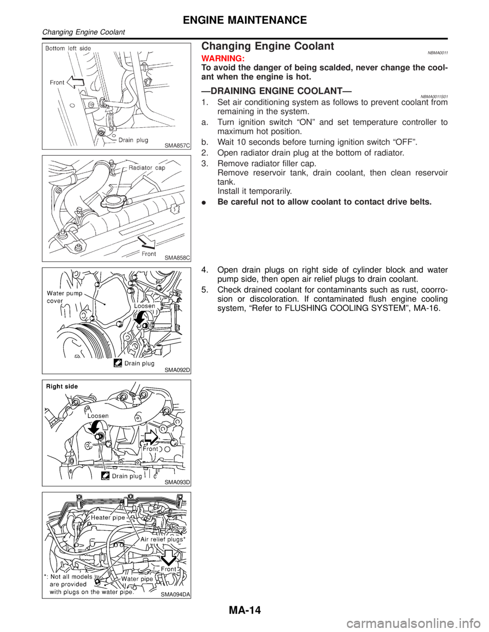
Changing Engine CoolantNBMA0011WARNING:
To avoid the danger of being scalded, never change the cool-
ant when the engine is hot.
ÐDRAINING ENGINE COOLANTÐNBMA0011S011. Set air conditioning system as follows to prevent coolant from
remaining in the system.
a. Turn ignition switch ªONº and set temperature controller to
maximum hot position.
b. Wait 10 seconds before turning ignition switch ªOFFº.
2. Open radiator drain plug at the bottom of radiator.
3. Remove radiator filler cap.
Remove reservoir tank, drain coolant, then clean reservoir
tank.
Install it temporarily.
IBe careful not to allow coolant to contact drive belts.
SMA092D
SMA093D
SMA094DA
4. Open drain plugs on right side of cylinder block and water
pump side, then open air relief plugs to drain coolant.
5. Check drained coolant for contaminants such as rust, coorro-
sion or discoloration. If contaminated flush engine cooling
system, ªRefer to FLUSHING COOLING SYSTEMº, MA-16.
ENGINE MAINTENANCE
Changing Engine Coolant
MA-14
Page 2010 of 2395

SMA182B
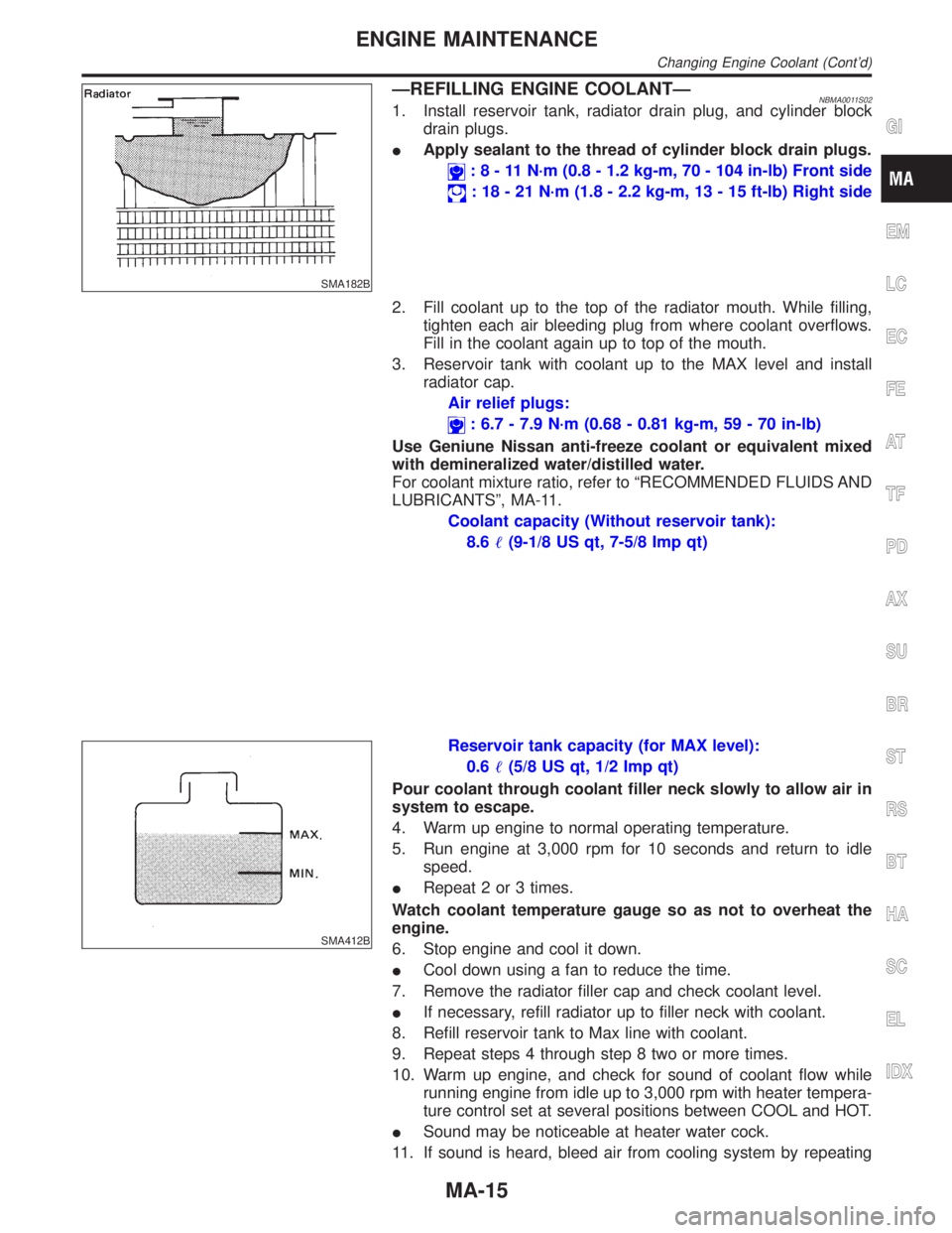
ÐREFILLING ENGINE COOLANTÐNBMA0011S021. Install reservoir tank, radiator drain plug, and cylinder block
drain plugs.
IApply sealant to the thread of cylinder block drain plugs.
:8-11N´m(0.8 - 1.2 kg-m, 70 - 104 in-lb) Front side
: 18 - 21 N´m (1.8 - 2.2 kg-m, 13 - 15 ft-lb) Right side
2. Fill coolant up to the top of the radiator mouth. While filling,
tighten each air bleeding plug from where coolant overflows.
Fill in the coolant again up to top of the mouth.
3. Reservoir tank with coolant up to the MAX level and install
radiator cap.
Air relief plugs:
: 6.7 - 7.9 N´m (0.68 - 0.81 kg-m, 59 - 70 in-lb)
Use Geniune Nissan anti-freeze coolant or equivalent mixed
with demineralized water/distilled water.
For coolant mixture ratio, refer to ªRECOMMENDED FLUIDS AND
LUBRICANTSº, MA-11.
Coolant capacity (Without reservoir tank):
8.6(9-1/8 US qt, 7-5/8 Imp qt)
SMA412B
Reservoir tank capacity (for MAX level):
0.6(5/8 US qt, 1/2 Imp qt)
Pour coolant through coolant filler neck slowly to allow air in
system to escape.
4. Warm up engine to normal operating temperature.
5. Run engine at 3,000 rpm for 10 seconds and return to idle
speed.
IRepeat 2 or 3 times.
Watch coolant temperature gauge so as not to overheat the
engine.
6. Stop engine and cool it down.
ICool down using a fan to reduce the time.
7. Remove the radiator filler cap and check coolant level.
IIf necessary, refill radiator up to filler neck with coolant.
8. Refill reservoir tank to Max line with coolant.
9. Repeat steps 4 through step 8 two or more times.
10. Warm up engine, and check for sound of coolant flow while
running engine from idle up to 3,000 rpm with heater tempera-
ture control set at several positions between COOL and HOT.
ISound may be noticeable at heater water cock.
11. If sound is heard, bleed air from cooling system by repeating
GI
EM
LC
EC
FE
AT
TF
PD
AX
SU
BR
ST
RS
BT
HA
SC
EL
IDX
ENGINE MAINTENANCE
Changing Engine Coolant (Cont'd)
MA-15