Oil sensor plug INFINITI QX4 2001 Factory Service Manual
[x] Cancel search | Manufacturer: INFINITI, Model Year: 2001, Model line: QX4, Model: INFINITI QX4 2001Pages: 2395, PDF Size: 43.2 MB
Page 13 of 2395
IBefore assembly, apply a coat of recommended ATF to all
parts. Apply petroleum jelly to protect O-rings and seals, or
hold bearings and washers in place during assembly. Do not
use grease.
IExtreme care should be taken to avoid damage to O-rings,
seals and gaskets when assembling.
IReplace ATF cooler if excessive foreign material is found in oil
pan or clogging strainer. Refer to ªATF COOLER SERVICEº,
AT-9.
IAfter overhaul, refill the transmission with new ATF.
IWhen the A/T drain plug is removed, only some of the fluid is
drained. Old A/T fluid will remain in torque converter and ATF
cooling system.
Always follow the procedures when changing A/T fluid. Refer
to MA-21, ªChanging A/T Fluidº.
Service Notice or PrecautionsNBAT0004FAIL-SAFENBAT0004S01The TCM has an electronic Fail-Safe (limp home mode). This allows the vehicle to be driven even if a major
electrical input/output device circuit is damaged.
Under Fail-Safe, the vehicle always runs in third gear, even with a shift lever position of ª1º, ª2º or ªDº. The
customer may complain of sluggish or poor acceleration.
When the ignition key is turned ªONº following Fail-Safe operation, O/D OFF indicator lamp blinks for about
8 seconds. (For ªTCM SELF-DIAGNOSTIC PROCEDURE (No Tools)º, refer to AT-46.)
Fail-Safe may occur without electrical circuit damage if the vehicle is driven under extreme conditions (such
as excessive wheel spin followed by sudden braking). To recover normal shift pattern, turn the ignition key
ªOFFº for 5 seconds, then ªONº.
The blinking of the O/D OFF indicator lamp for about 8 seconds will appear only once and be cleared. The
customer may resume normal driving conditions.
Always follow the ªWORK FLOWº (Refer to AT-57).
The SELF-DIAGNOSIS results will be as follows:
The first SELF-DIAGNOSIS will indicate damage to the vehicle speed sensor or the revolution sensor.
During the next SELF-DIAGNOSIS, performed after checking the sensor, no damages will be indicated.
TORQUE CONVERTER SERVICENBAT0004S04The torque converter should be replaced under any of the following conditions:
IExternal leaks in the hub weld area.
IConverter hub is scored or damaged.
IConverter pilot is broken, damaged or fits poorly into crankshaft.
ISteel particles are found after flushing the cooler and cooler lines.
IPump is damaged or steel particles are found in the converter.
IVehicle has TCC shudder and/or no TCC apply. Replace only after all hydraulic and electrical diagnoses
have been made. (Converter clutch material may be glazed.)
IConverter is contaminated with engine coolant containing antifreeze.
IInternal failure of stator roller clutch.
IHeavy clutch debris due to overheating (blue converter).
ISteel particles or clutch lining material found in fluid filter or on magnet when no internal parts in unit are
worn or damaged Ð indicates that lining material came from converter.
The torque converter should not be replaced if:
IThe fluid has an odor, is discolored, and there is no evidence of metal or clutch facing particles.
PRECAUTIONS
Precautions (Cont'd)
AT-8
Page 68 of 2395
SAT493G
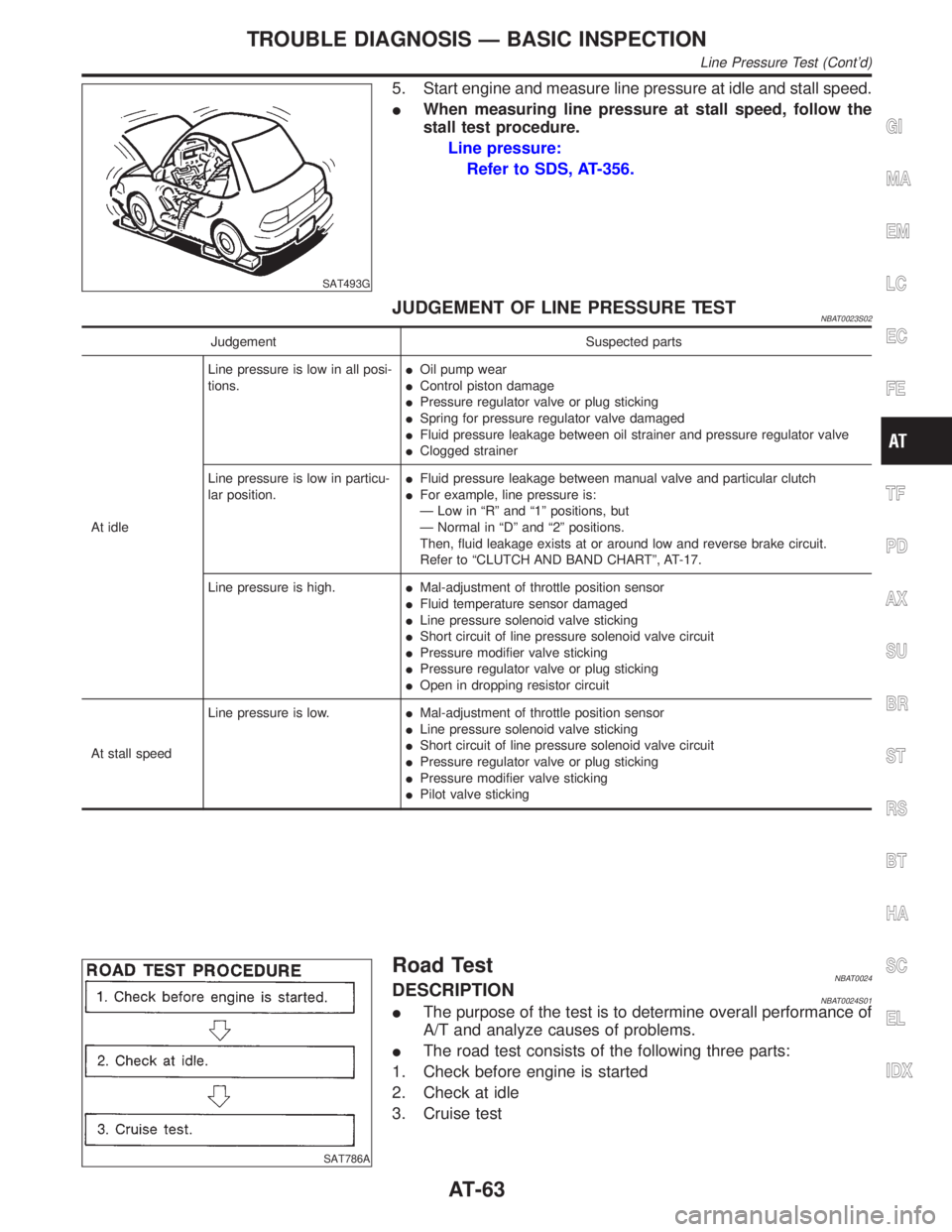
5. Start engine and measure line pressure at idle and stall speed.
IWhen measuring line pressure at stall speed, follow the
stall test procedure.
Line pressure:
Refer to SDS, AT-356.
JUDGEMENT OF LINE PRESSURE TESTNBAT0023S02
Judgement Suspected parts
At idleLine pressure is low in all posi-
tions.IOil pump wear
IControl piston damage
IPressure regulator valve or plug sticking
ISpring for pressure regulator valve damaged
IFluid pressure leakage between oil strainer and pressure regulator valve
IClogged strainer
Line pressure is low in particu-
lar position.IFluid pressure leakage between manual valve and particular clutch
IFor example, line pressure is:
Ð Low in ªRº and ª1º positions, but
Ð Normal in ªDº and ª2º positions.
Then, fluid leakage exists at or around low and reverse brake circuit.
Refer to ªCLUTCH AND BAND CHARTº, AT-17.
Line pressure is high.IMal-adjustment of throttle position sensor
IFluid temperature sensor damaged
ILine pressure solenoid valve sticking
IShort circuit of line pressure solenoid valve circuit
IPressure modifier valve sticking
IPressure regulator valve or plug sticking
IOpen in dropping resistor circuit
At stall speedLine pressure is low.IMal-adjustment of throttle position sensor
ILine pressure solenoid valve sticking
IShort circuit of line pressure solenoid valve circuit
IPressure regulator valve or plug sticking
IPressure modifier valve sticking
IPilot valve sticking
SAT786A
Road TestNBAT0024DESCRIPTIONNBAT0024S01IThe purpose of the test is to determine overall performance of
A/T and analyze causes of problems.
IThe road test consists of the following three parts:
1. Check before engine is started
2. Check at idle
3. Cruise test
GI
MA
EM
LC
EC
FE
TF
PD
AX
SU
BR
ST
RS
BT
HA
SC
EL
IDX
TROUBLE DIAGNOSIS Ð BASIC INSPECTION
Line Pressure Test (Cont'd)
AT-63
Page 282 of 2395
RemovalNBAT0214
SAT362IA
SAT163K
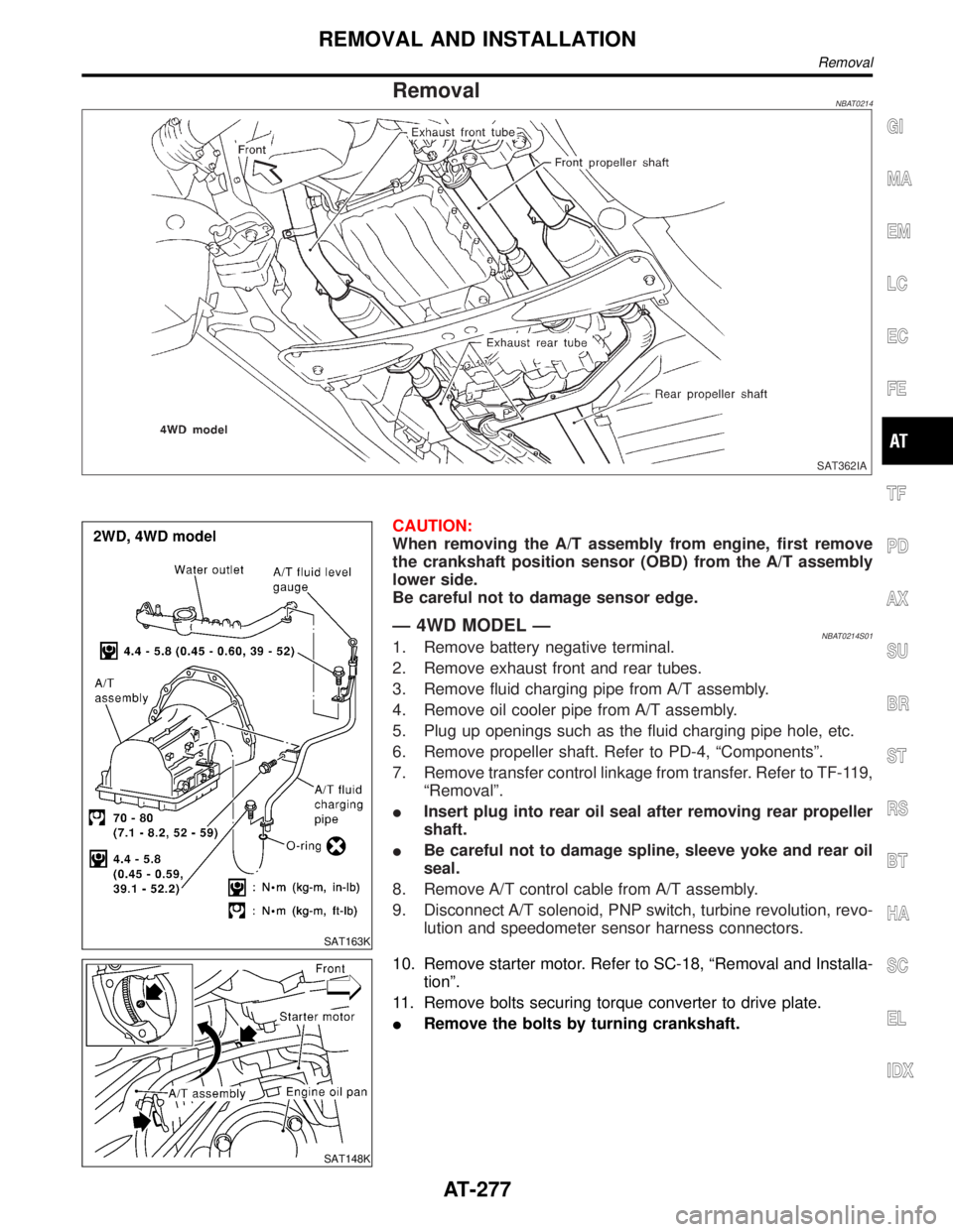
CAUTION:
When removing the A/T assembly from engine, first remove
the crankshaft position sensor (OBD) from the A/T assembly
lower side.
Be careful not to damage sensor edge.
Ð 4WD MODEL ÐNBAT0214S011. Remove battery negative terminal.
2. Remove exhaust front and rear tubes.
3. Remove fluid charging pipe from A/T assembly.
4. Remove oil cooler pipe from A/T assembly.
5. Plug up openings such as the fluid charging pipe hole, etc.
6. Remove propeller shaft. Refer to PD-4, ªComponentsº.
7. Remove transfer control linkage from transfer. Refer to TF-119,
ªRemovalº.
IInsert plug into rear oil seal after removing rear propeller
shaft.
IBe careful not to damage spline, sleeve yoke and rear oil
seal.
8. Remove A/T control cable from A/T assembly.
9. Disconnect A/T solenoid, PNP switch, turbine revolution, revo-
lution and speedometer sensor harness connectors.
SAT148K
10. Remove starter motor. Refer to SC-18, ªRemoval and Installa-
tionº.
11. Remove bolts securing torque converter to drive plate.
IRemove the bolts by turning crankshaft.
GI
MA
EM
LC
EC
FE
TF
PD
AX
SU
BR
ST
RS
BT
HA
SC
EL
IDX
REMOVAL AND INSTALLATION
Removal
AT-277
Page 283 of 2395
SAT801C
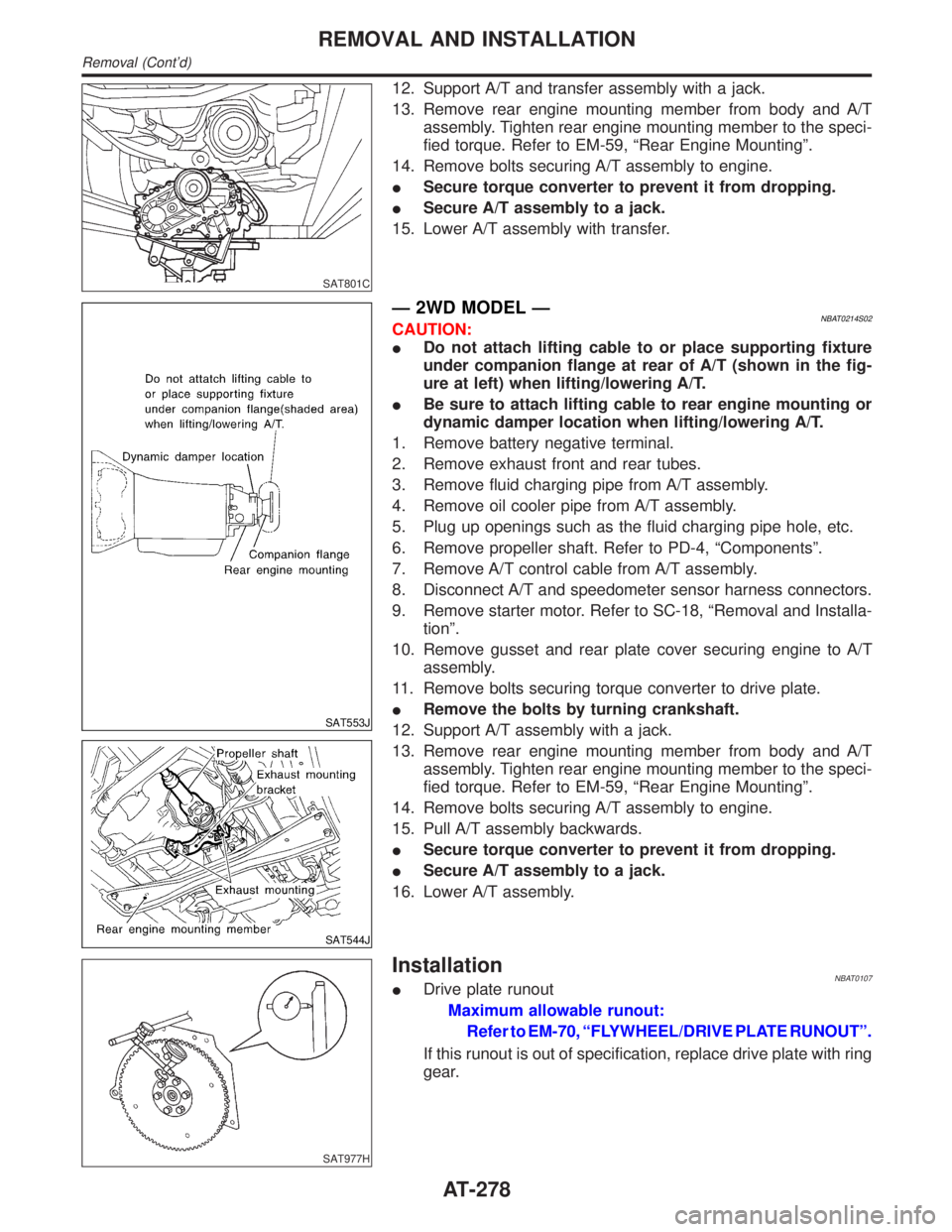
12. Support A/T and transfer assembly with a jack.
13. Remove rear engine mounting member from body and A/T
assembly. Tighten rear engine mounting member to the speci-
fied torque. Refer to EM-59, ªRear Engine Mountingº.
14. Remove bolts securing A/T assembly to engine.
ISecure torque converter to prevent it from dropping.
ISecure A/T assembly to a jack.
15. Lower A/T assembly with transfer.
SAT553J
SAT544J
Ð 2WD MODEL ÐNBAT0214S02CAUTION:
IDo not attach lifting cable to or place supporting fixture
under companion flange at rear of A/T (shown in the fig-
ure at left) when lifting/lowering A/T.
IBe sure to attach lifting cable to rear engine mounting or
dynamic damper location when lifting/lowering A/T.
1. Remove battery negative terminal.
2. Remove exhaust front and rear tubes.
3. Remove fluid charging pipe from A/T assembly.
4. Remove oil cooler pipe from A/T assembly.
5. Plug up openings such as the fluid charging pipe hole, etc.
6. Remove propeller shaft. Refer to PD-4, ªComponentsº.
7. Remove A/T control cable from A/T assembly.
8. Disconnect A/T and speedometer sensor harness connectors.
9. Remove starter motor. Refer to SC-18, ªRemoval and Installa-
tionº.
10. Remove gusset and rear plate cover securing engine to A/T
assembly.
11. Remove bolts securing torque converter to drive plate.
IRemove the bolts by turning crankshaft.
12. Support A/T assembly with a jack.
13. Remove rear engine mounting member from body and A/T
assembly. Tighten rear engine mounting member to the speci-
fied torque. Refer to EM-59, ªRear Engine Mountingº.
14. Remove bolts securing A/T assembly to engine.
15. Pull A/T assembly backwards.
ISecure torque converter to prevent it from dropping.
ISecure A/T assembly to a jack.
16. Lower A/T assembly.
SAT977H
InstallationNBAT0107IDrive plate runout
Maximum allowable runout:
Refer to EM-70, ªFLYWHEEL/DRIVE PLATE RUNOUTº.
If this runout is out of specification, replace drive plate with ring
gear.
REMOVAL AND INSTALLATION
Removal (Cont'd)
AT-278
Page 291 of 2395
NBAT0111
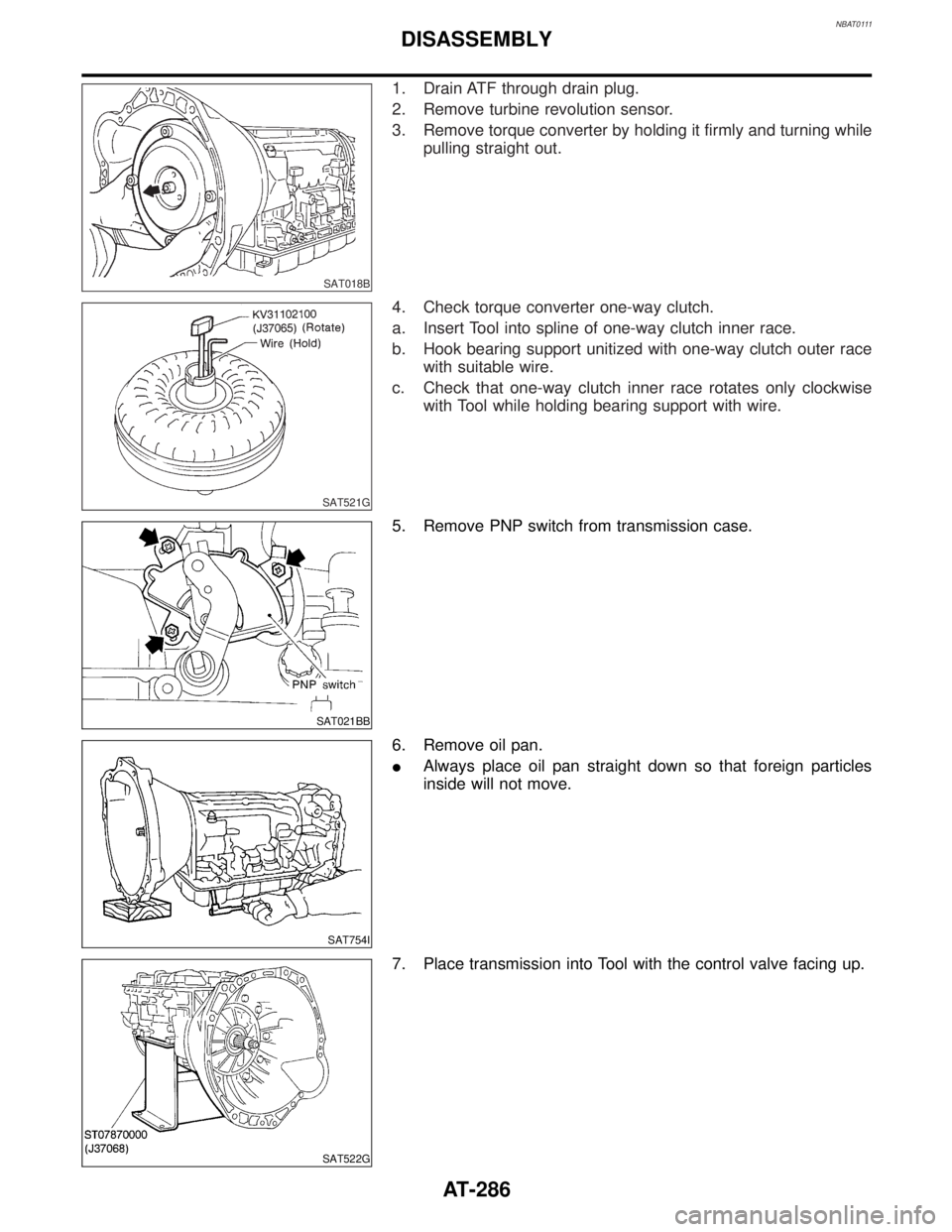
SAT018B
1. Drain ATF through drain plug.
2. Remove turbine revolution sensor.
3. Remove torque converter by holding it firmly and turning while
pulling straight out.
SAT521G
4. Check torque converter one-way clutch.
a. Insert Tool into spline of one-way clutch inner race.
b. Hook bearing support unitized with one-way clutch outer race
with suitable wire.
c. Check that one-way clutch inner race rotates only clockwise
with Tool while holding bearing support with wire.
SAT021BB
5. Remove PNP switch from transmission case.
SAT754I
6. Remove oil pan.
IAlways place oil pan straight down so that foreign particles
inside will not move.
SAT522G
7. Place transmission into Tool with the control valve facing up.
DISASSEMBLY
AT-286
Page 359 of 2395
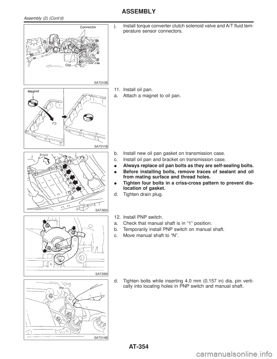
SAT010B
j. Install torque converter clutch solenoid valve and A/T fluid tem-
perature sensor connectors.
SAT011B
11. Install oil pan.
a. Attach a magnet to oil pan.
SAT365I
b. Install new oil pan gasket on transmission case.
c. Install oil pan and bracket on transmission case.
IAlways replace oil pan bolts as they are self-sealing bolts.
IBefore installing bolts, remove traces of sealant and oil
from mating surface and thread holes.
ITighten four bolts in a criss-cross pattern to prevent dis-
location of gasket.
d. Tighten drain plug.
SAT299I
12. Install PNP switch.
a. Check that manual shaft is in ª1º position.
b. Temporarily install PNP switch on manual shaft.
c. Move manual shaft to ªNº.
SAT014B
d. Tighten bolts while inserting 4.0 mm (0.157 in) dia. pin verti-
cally into locating holes in PNP switch and manual shaft.
ASSEMBLY
Assembly (2) (Cont'd)
AT-354
Page 626 of 2395
![INFINITI QX4 2001 Factory Service Manual Monitored item [Unit]ECM
input
signalsMain
signalsDescription Remarks
A/F ALPHA-B1 [%]q
IIndicates the mean value of the air-fuel ratio
feedback correction factor per cycle.IWhen the engine is running INFINITI QX4 2001 Factory Service Manual Monitored item [Unit]ECM
input
signalsMain
signalsDescription Remarks
A/F ALPHA-B1 [%]q
IIndicates the mean value of the air-fuel ratio
feedback correction factor per cycle.IWhen the engine is running](/img/42/57027/w960_57027-625.png)
Monitored item [Unit]ECM
input
signalsMain
signalsDescription Remarks
A/F ALPHA-B1 [%]q
IIndicates the mean value of the air-fuel ratio
feedback correction factor per cycle.IWhen the engine is running, specifi-
cation range is indicated.
IThis data also includes the data for
the air-fuel ratio learning control. A/F ALPHA-B2 [%]q
NOTE:
IAny monitored item that does not match the vehicle being diagnosed is deleted from the display automatically.
IRegarding R50 model, ªB1º indicates bank 1 and ªB2º indicates bank 2.
ACTIVE TEST MODENBEC0034S07
TEST ITEM CONDITION JUDGEMENT CHECK ITEM (REMEDY)
FUEL INJECTIONIEngine: Return to the original
trouble condition
IChange the amount of fuel injec-
tion using CONSULT-II.If trouble symptom disappears, see
CHECK ITEM.IHarness and connector
IFuel injectors
IHeated oxygen sensor
IGNITION TIMINGIEngine: Return to the original
trouble condition
ITiming light: Set
IRetard the ignition timing using
CONSULT-II.If trouble symptom disappears, see
CHECK ITEM.IAdjust initial ignition timing
IACV-AAC/V
OPENINGIEngine: After warming up, idle
the engine.
IChange the IACV-AAC valve
opening percent using CON-
SULT-II.Engine speed changes according
to the opening percent.IHarness and connector
IIACV-AAC valve
POWER BAL-
ANCEIEngine: After warming up, idle
the engine.
IA/C switch ªOFFº
IShift lever ªNº
ICut off each injector signal one
at a time using CONSULT-II.Engine runs rough or dies.IHarness and connector
ICompression
IInjectors
IPower transistor
ISpark plugs
IIgnition coils
ENG COOLANT
TEMPIEngine: Return to the original
trouble condition
IChange the engine coolant tem-
perature using CONSULT-II.If trouble symptom disappears, see
CHECK ITEM.IHarness and connector
IEngine coolant temperature sen-
sor
IFuel injectors
FUEL PUMP
RELAYIIgnition switch: ON
(Engine stopped)
ITurn the fuel pump relay ªONº
and ªOFFº using CONSULT-II
and listen to operating sound.Fuel pump relay makes the operat-
ing sound.IHarness and connector
IFuel pump relay
VIAS SOL VALVEIIgnition switch: ON
ITurn solenoid valve ªONº and
ªOFFº with CONSULT-II and lis-
ten for operating sound.Solenoid valve makes an operating
sound.IHarness and connector
ISolenoid valve
SWIRL CONT
S O L VA LV EIIgnition switch: ON
ITurn solenoid valve ªONº and
ªOFFº with CONSULT-II and lis-
ten for operating sound.Solenoid valve makes an operating
sound.IHarness and connector
ISolenoid valve
PURG VOL
CONT/VIEngine: After warming up, run
engine at 1,500 rpm.
IChange the EVAP canister purge
volume control solenoid valve
opening percent using CON-
SULT-II.Engine speed changes according
to the opening percent.IHarness and connector
ISolenoid valve
GI
MA
EM
LC
FE
AT
TF
PD
AX
SU
BR
ST
RS
BT
HA
SC
EL
IDX
ON BOARD DIAGNOSTIC SYSTEM DESCRIPTION
CONSULT-II (Cont'd)
EC-91
Page 1658 of 2395
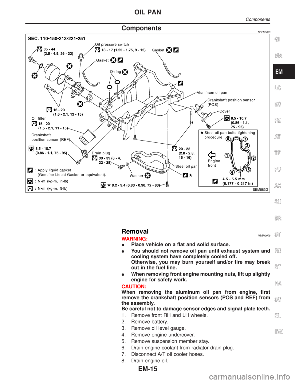
ComponentsNBEM0008
SEM583G
RemovalNBEM0009WARNING:
IPlace vehicle on a flat and solid surface.
IYou should not remove oil pan until exhaust system and
cooling system have completely cooled off.
Otherwise, you may burn yourself and/or fire may break
out in the fuel line.
IWhen removing front engine mounting nuts, lift up slightly
engine for safety work.
CAUTION:
When removing the aluminum oil pan from engine, first
remove the crankshaft position sensors (POS and REF) from
the assembly.
Be careful not to damage sensor edges and signal plate teeth.
1. Remove front RH and LH wheels.
2. Remove battery.
3. Remove oil level gauge.
4. Remove engine undercover.
5. Remove suspension member stay.
6. Drain engine coolant from radiator drain plug.
7. Disconnect A/T oil cooler hoses.
8. Drain engine oil.
GI
MA
LC
EC
FE
AT
TF
PD
AX
SU
BR
ST
RS
BT
HA
SC
EL
IDX
OIL PAN
Components
EM-15
Page 1678 of 2395
SEM948E
ReplacementNBEM0015CAUTION:
When removing the oil pans, oil pump assembly and timing
chain from engine, first remove the camshaft position sensor
(PHASE), CVTC sensor and the crankshaft position sensors
(REF)/(POS) from the assembly.
Be careful not to damage sensor edges.
VALVE OIL SEALNBEM0015S011. Remove timing chain. Refer to ªRemoval, EM-23.
2. Remove camshaft brackets and camshaft. Refer to
ªDisassemblyº, EM-41.
3. Remove valve lifters and shims.
4. Remove valve spring with Tool.
5. Reinstall any parts removed in reverse order of removal.
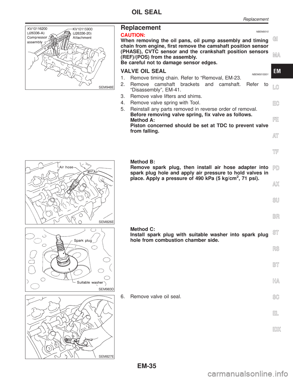
Before removing valve spring, fix valve as follows.
Method A:
Piston concerned should be set at TDC to prevent valve
from falling.
SEM826E
Method B:
Remove spark plug, then install air hose adapter into
spark plug hole and apply air pressure to hold valves in
place. Apply a pressure of 490 kPa (5 kg/cm
2, 71 psi).
SEM983D
Method C:
Install spark plug with suitable washer into spark plug
hole from combustion chamber side.
SEM827E
6. Remove valve oil seal.
GI
MA
LC
EC
FE
AT
TF
PD
AX
SU
BR
ST
RS
BT
HA
SC
EL
IDX
OIL SEAL
Replacement
EM-35
Page 1704 of 2395

ComponentsNBEM0024
SEM584G
1. Rear oil seal retainer
2. Cylinder block
3. Knock sensor
4. Upper main bearing
5. Lower main bearing
6. Oil jet
7. Water drain plug (RH side)
8. Water drain plug (Water pump
side)9. Main bearing cap
10. Main bearing beam
11. Crankshaft
12. Pilot converter
13. Drive plate with signal plate
14. Drive plate reinforce plate
15. Oil ring
16. Piston pin17. Connecting rod bearing
18. Connecting rod
19. Piston
20. Top ring
21. 2nd ring
22. Baffle plate
23. Water drain plug (LH side)
GI
MA
LC
EC
FE
AT
TF
PD
AX
SU
BR
ST
RS
BT
HA
SC
EL
IDX
CYLINDER BLOCK
Components
EM-61