air conditioning INFINITI QX4 2001 Factory Service Manual
[x] Cancel search | Manufacturer: INFINITI, Model Year: 2001, Model line: QX4, Model: INFINITI QX4 2001Pages: 2395, PDF Size: 43.2 MB
Page 536 of 2395
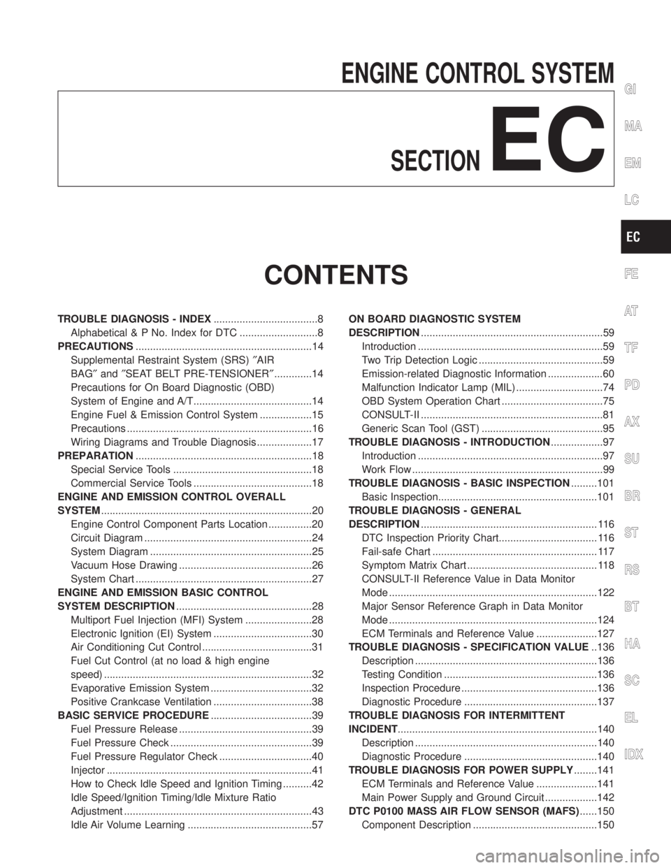
ENGINE CONTROL SYSTEM
SECTION
EC
CONTENTS
TROUBLE DIAGNOSIS - INDEX....................................8
Alphabetical & P No. Index for DTC ...........................8
PRECAUTIONS.............................................................14
Supplemental Restraint System (SRS)²AIR
BAG²and²SEAT BELT PRE-TENSIONER².............14
Precautions for On Board Diagnostic (OBD)
System of Engine and A/T.........................................14
Engine Fuel & Emission Control System ..................15
Precautions ................................................................16
Wiring Diagrams and Trouble Diagnosis ...................17
PREPARATION.............................................................18
Special Service Tools ................................................18
Commercial Service Tools .........................................18
ENGINE AND EMISSION CONTROL OVERALL
SYSTEM.........................................................................20
Engine Control Component Parts Location ...............20
Circuit Diagram ..........................................................24
System Diagram ........................................................25
Vacuum Hose Drawing ..............................................26
System Chart .............................................................27
ENGINE AND EMISSION BASIC CONTROL
SYSTEM DESCRIPTION...............................................28
Multiport Fuel Injection (MFI) System .......................28
Electronic Ignition (EI) System ..................................30
Air Conditioning Cut Control ......................................31
Fuel Cut Control (at no load & high engine
speed) ........................................................................32
Evaporative Emission System ...................................32
Positive Crankcase Ventilation ..................................38
BASIC SERVICE PROCEDURE...................................39
Fuel Pressure Release ..............................................39
Fuel Pressure Check .................................................39
Fuel Pressure Regulator Check ................................40
Injector .......................................................................41
How to Check Idle Speed and Ignition Timing ..........42
Idle Speed/Ignition Timing/Idle Mixture Ratio
Adjustment .................................................................43
Idle Air Volume Learning ...........................................57ON BOARD DIAGNOSTIC SYSTEM
DESCRIPTION...............................................................59
Introduction ................................................................59
Two Trip Detection Logic ...........................................59
Emission-related Diagnostic Information ...................60
Malfunction Indicator Lamp (MIL) ..............................74
OBD System Operation Chart ...................................75
CONSULT-II ...............................................................81
Generic Scan Tool (GST) ..........................................95
TROUBLE DIAGNOSIS - INTRODUCTION..................97
Introduction ................................................................97
Work Flow ..................................................................99
TROUBLE DIAGNOSIS - BASIC INSPECTION.........101
Basic Inspection.......................................................101
TROUBLE DIAGNOSIS - GENERAL
DESCRIPTION............................................................. 116
DTC Inspection Priority Chart.................................. 116
Fail-safe Chart ......................................................... 117
Symptom Matrix Chart ............................................. 118
CONSULT-II Reference Value in Data Monitor
Mode ........................................................................122
Major Sensor Reference Graph in Data Monitor
Mode ........................................................................124
ECM Terminals and Reference Value .....................127
TROUBLE DIAGNOSIS - SPECIFICATION VALUE..136
Description ...............................................................136
Testing Condition .....................................................136
Inspection Procedure ...............................................136
Diagnostic Procedure ..............................................137
TROUBLE DIAGNOSIS FOR INTERMITTENT
INCIDENT.....................................................................140
Description ...............................................................140
Diagnostic Procedure ..............................................140
TROUBLE DIAGNOSIS FOR POWER SUPPLY........141
ECM Terminals and Reference Value .....................141
Main Power Supply and Ground Circuit ..................142
DTC P0100 MASS AIR FLOW SENSOR (MAFS)......150
Component Description ...........................................150
GI
MA
EM
LC
FE
AT
TF
PD
AX
SU
BR
ST
RS
BT
HA
SC
EL
IDX
Page 562 of 2395
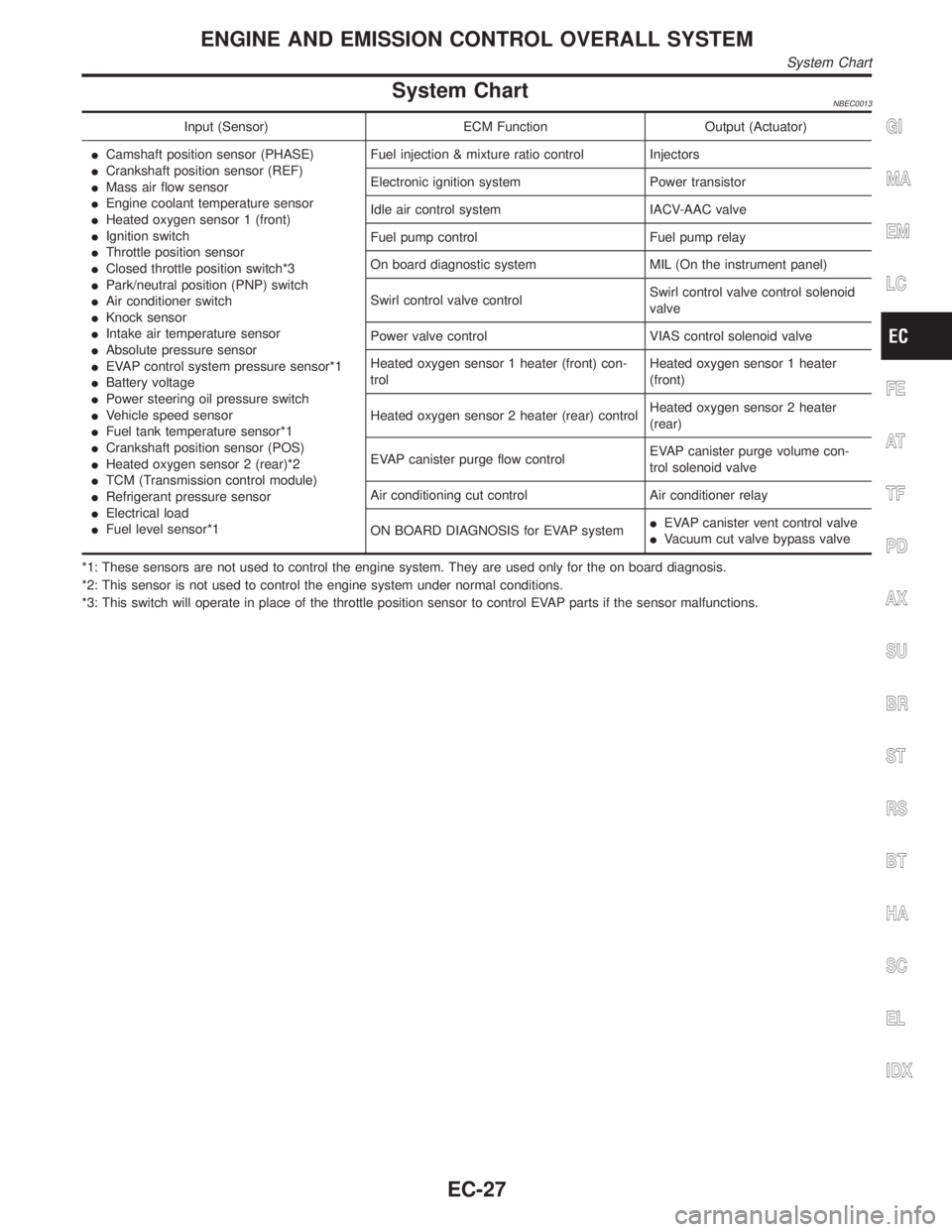
System ChartNBEC0013
Input (Sensor) ECM Function Output (Actuator)
ICamshaft position sensor (PHASE)
ICrankshaft position sensor (REF)
IMass air flow sensor
IEngine coolant temperature sensor
IHeated oxygen sensor 1 (front)
IIgnition switch
IThrottle position sensor
IClosed throttle position switch*3
IPark/neutral position (PNP) switch
IAir conditioner switch
IKnock sensor
IIntake air temperature sensor
IAbsolute pressure sensor
IEVAP control system pressure sensor*1
IBattery voltage
IPower steering oil pressure switch
IVehicle speed sensor
IFuel tank temperature sensor*1
ICrankshaft position sensor (POS)
IHeated oxygen sensor 2 (rear)*2
ITCM (Transmission control module)
IRefrigerant pressure sensor
IElectrical load
IFuel level sensor*1Fuel injection & mixture ratio control Injectors
Electronic ignition system Power transistor
Idle air control system IACV-AAC valve
Fuel pump control Fuel pump relay
On board diagnostic system MIL (On the instrument panel)
Swirl control valve controlSwirl control valve control solenoid
valve
Power valve control VIAS control solenoid valve
Heated oxygen sensor 1 heater (front) con-
trolHeated oxygen sensor 1 heater
(front)
Heated oxygen sensor 2 heater (rear) controlHeated oxygen sensor 2 heater
(rear)
EVAP canister purge flow controlEVAP canister purge volume con-
trol solenoid valve
Air conditioning cut control Air conditioner relay
ON BOARD DIAGNOSIS for EVAP systemIEVAP canister vent control valve
IVacuum cut valve bypass valve
*1: These sensors are not used to control the engine system. They are used only for the on board diagnosis.
*2: This sensor is not used to control the engine system under normal conditions.
*3: This switch will operate in place of the throttle position sensor to control EVAP parts if the sensor malfunctions.GI
MA
EM
LC
FE
AT
TF
PD
AX
SU
BR
ST
RS
BT
HA
SC
EL
IDX
ENGINE AND EMISSION CONTROL OVERALL SYSTEM
System Chart
EC-27
Page 566 of 2395
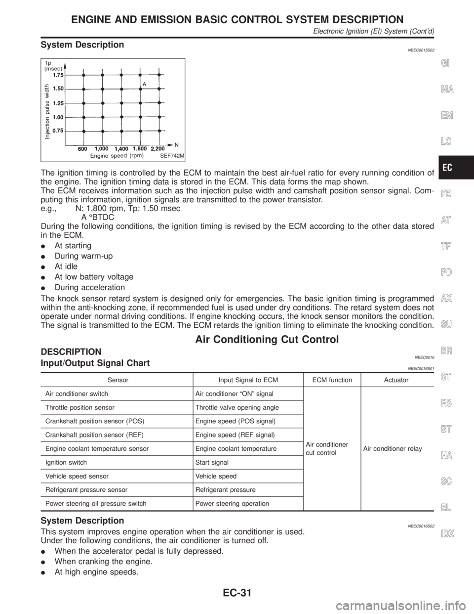
System DescriptionNBEC0015S02
SEF742M
The ignition timing is controlled by the ECM to maintain the best air-fuel ratio for every running condition of
the engine. The ignition timing data is stored in the ECM. This data forms the map shown.
The ECM receives information such as the injection pulse width and camshaft position sensor signal. Com-
puting this information, ignition signals are transmitted to the power transistor.
e.g., N: 1,800 rpm, Tp: 1.50 msec
A ÉBTDC
During the following conditions, the ignition timing is revised by the ECM according to the other data stored
in the ECM.
IAt starting
IDuring warm-up
IAt idle
IAt low battery voltage
IDuring acceleration
The knock sensor retard system is designed only for emergencies. The basic ignition timing is programmed
within the anti-knocking zone, if recommended fuel is used under dry conditions. The retard system does not
operate under normal driving conditions. If engine knocking occurs, the knock sensor monitors the condition.
The signal is transmitted to the ECM. The ECM retards the ignition timing to eliminate the knocking condition.
Air Conditioning Cut Control
DESCRIPTIONNBEC0016Input/Output Signal ChartNBEC0016S01
Sensor Input Signal to ECM ECM function Actuator
Air conditioner switch Air conditioner ªONº signal
Air conditioner
cut controlAir conditioner relay Throttle position sensor Throttle valve opening angle
Crankshaft position sensor (POS) Engine speed (POS signal)
Crankshaft position sensor (REF) Engine speed (REF signal)
Engine coolant temperature sensor Engine coolant temperature
Ignition switch Start signal
Vehicle speed sensor Vehicle speed
Refrigerant pressure sensor Refrigerant pressure
Power steering oil pressure switch Power steering operation
System DescriptionNBEC0016S02This system improves engine operation when the air conditioner is used.
Under the following conditions, the air conditioner is turned off.
IWhen the accelerator pedal is fully depressed.
IWhen cranking the engine.
IAt high engine speeds.
GI
MA
EM
LC
FE
AT
TF
PD
AX
SU
BR
ST
RS
BT
HA
SC
EL
IDX
ENGINE AND EMISSION BASIC CONTROL SYSTEM DESCRIPTION
Electronic Ignition (EI) System (Cont'd)
EC-31
Page 567 of 2395
IWhen the engine coolant temperature becomes excessively high.
IWhen operating power steering during low engine speed or low vehicle speed.
IWhen engine speed is excessively low.
IWhen refrigerant pressure is excessively low or high.
Fuel Cut Control (at no load & high engine
speed)
DESCRIPTIONNBEC0017Input/Output Signal ChartNBEC0017S01
Sensor Input Signal to ECMECM func-
tionActuator
Vehicle speed sensor Vehicle speed
Fuel cut
controlInjectors Park/neutral position (PNP) switch Neutral position
Throttle position sensor Throttle position
Engine coolant temperature sensor Engine coolant temperature
Crankshaft position sensor (POS) Engine speed (POS signal)
Crankshaft position sensor (REF) Engine speed (REF signal)
If the engine speed is above 1,800 rpm with no load (for example, in neutral and engine speed over 1,800
rpm) fuel will be cut off after some time. The exact time when the fuel is cut off varies based on engine speed.
Fuel cut will operate until the engine speed reaches 1,500 rpm, then fuel cut is cancelled.
NOTE:
This function is different from deceleration control listed under ªMultiport Fuel Injection (MFI) Systemº, EC-28.
Evaporative Emission System
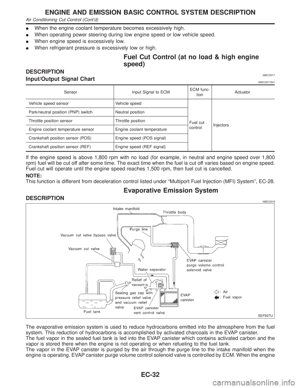
DESCRIPTIONNBEC0018
SEF927U
The evaporative emission system is used to reduce hydrocarbons emitted into the atmosphere from the fuel
system. This reduction of hydrocarbons is accomplished by activated charcoals in the EVAP canister.
The fuel vapor in the sealed fuel tank is led into the EVAP canister which contains activated carbon and the
vapor is stored there when the engine is not operating or when refueling to the fuel tank.
The vapor in the EVAP canister is purged by the air through the purge line to the intake manifold when the
engine is operating. EVAP canister purge volume control solenoid valve is controlled by ECM. When the engine
ENGINE AND EMISSION BASIC CONTROL SYSTEM DESCRIPTION
Air Conditioning Cut Control (Cont'd)
EC-32
Page 592 of 2395

SEF452Y
Idle Air Volume LearningNBEC0642
SEF454Y
SEF455Y
DESCRIPTIONNBEC0642S01ªIdle Air Volume Learningº is an operation to learn the idle air vol-
ume that keeps each engine within the specific range. It must be
performed under any of the following conditions:
IEach time IACV-AAC valve, throttle body or ECM is replaced.
IIdle speed or ignition timing is out of specification.
PRE-CONDITIONINGNBEC0642S02Before performing ªIdle Air Volume Learningº, make sure that all of
the following conditions are satisfied.
Learning will be cancelled if any of the following conditions are
missed for even a moment.
IBattery voltage: More than 12.9V (At idle)
IEngine coolant temperature: 70 - 99ÉC (158 - 210ÉF)
IPNP switch: ON
IElectric load switch: OFF
(Air conditioner, headlamp, rear window defogger)
On vehicles equipped with daytime running light systems, if
the parking brake is applied before the engine is started the
headlamp will not illuminate.
ICooling fan motor: Not operating
ISteering wheel: Neutral (Straight-ahead position)
IVehicle speed: Stopped
ITransmission: Warmed-up
For A/T models with CONSULT-II, drive vehicle until ªFLUID
TEMP SEº in ªDATA MONITORº mode of ªA/Tº system indi-
cates less than 0.9V.
For A/T models without CONSULT-II, drive vehicle for 10 min-
utes.
OPERATION PROCEDURENBEC0642S03With CONSULT-IINBEC0642S03011. Turn ignition switch ªONº and wait at least 1 second.
2. Turn ignition switch ªOFFº and wait at least 10 seconds.
3. Start engine and warm it up to normal operating temperature.
4. Check that all items listed under the topic ªPRE-CONDITION-
INGº (previously mentioned) are in good order.
5. Turn ignition switch ªOFFº and wait at least 10 seconds.
6. Start the engine and let it idle for at least 30 seconds.
7. Select ªIDLE AIR VOL LEARNº in ªWORK SUPPORTº mode.
8. Touch ªSTARTº and wait 20 seconds.
9. Make sure that ªCMPLTº is displayed on CONSULT-II screen.
If ªINCMPº is displayed, ªIdle Air Volume Learningº will not be
carried out successfully. In this case, find the cause of the
problem by referring to the NOTE below.
10. Rev up the engine two or three times. Make sure that idle
speed and ignition timing are within specifications.
ITEM SPECIFICATION
Idle speed 750±50 rpm (in ªPº or ªNº position)
Ignition timing 15ɱ5É BTDC (in ªPº or ªNº position)
GI
MA
EM
LC
FE
AT
TF
PD
AX
SU
BR
ST
RS
BT
HA
SC
EL
IDX
BASIC SERVICE PROCEDURE
Idle Air Volume Learning
EC-57
Page 1745 of 2395
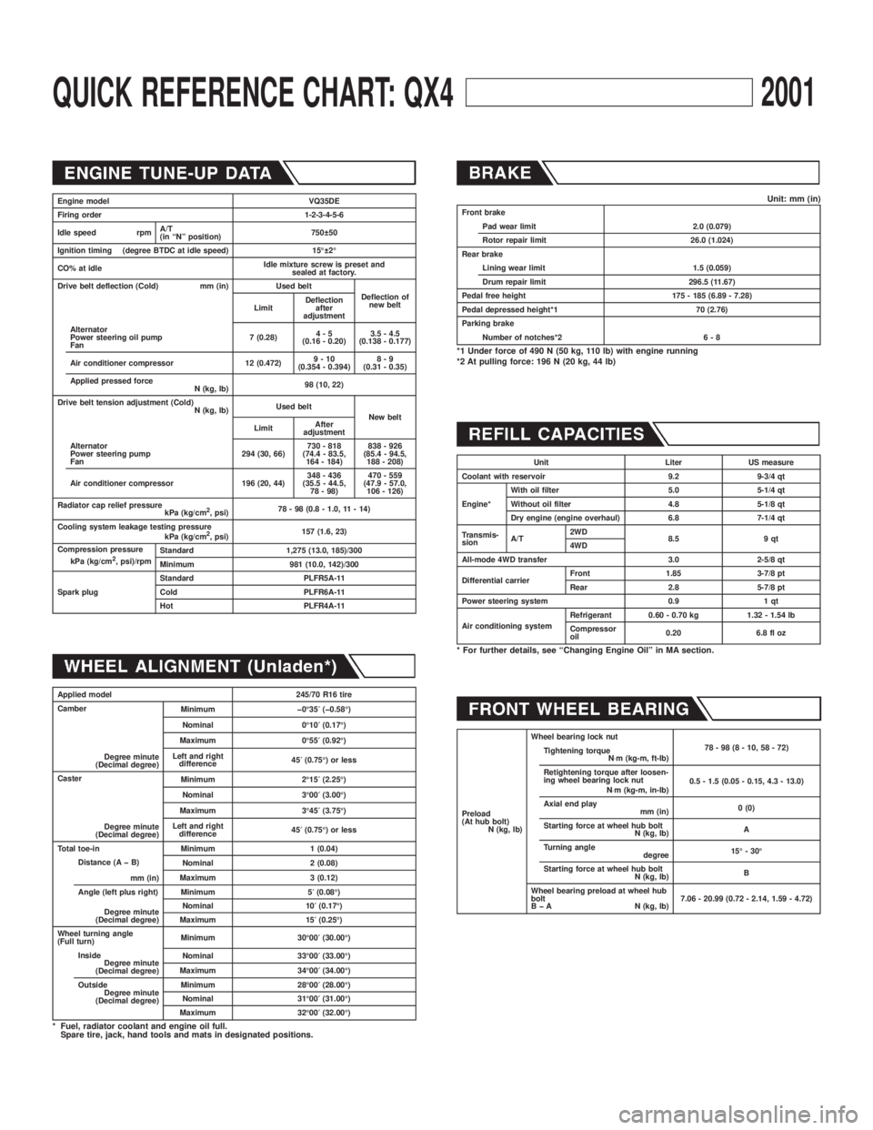
QUICK REFERENCE CHART: QX42001
Engine model VQ35DE
Firing order 1-2-3-4-5-6
Idle speed rpmA/T
(in ªNº position)750 50
Ignition timing (degree BTDC at idle speed) 15É 2É
CO% at idleIdle mixture screw is preset and
sealed at factory.
Drive belt deflection (Cold) mm (in) Used belt
Deflection of
new belt
LimitDeflection
after
adjustment
Alternator
Power steering oil pump
Fan7 (0.28)4-5
(0.16 - 0.20)3.5 - 4.5
(0.138 - 0.177)
Air conditioner compressor 12 (0.472)9-10
(0.354 - 0.394)8-9
(0.31 - 0.35)
Applied pressed force
N (kg, lb)98 (10, 22)
Drive belt tension adjustment (Cold)
N (kg, lb)Used belt
New belt
LimitAfter
adjustment
Alternator
Power steering pump
Fan294 (30, 66)730 - 818
(74.4 - 83.5,
164 - 184)838 - 926
(85.4 - 94.5,
188 - 208)
Air conditioner compressor 196 (20, 44)348 - 436
(35.5 - 44.5,
78 - 98)470 - 559
(47.9 - 57.0,
106 - 126)
Radiator cap relief pressure
kPa (kg/cm
2, psi)78 - 98 (0.8 - 1.0, 11 - 14)
Cooling system leakage testing pressure
kPa (kg/cm
2, psi)157 (1.6, 23)
Compression pressure
kPa (kg/cm
2, psi)/rpmStandard 1,275 (13.0, 185)/300
Minimum 981 (10.0, 142)/300
Spark plugStandard PLFR5A-11
Cold PLFR6A-11
Hot PLFR4A-11
Applied model 245/70 R16 tire
Camber
Degree minute
(Decimal degree)Minimum þ0É35¢(þ0.58É)
Nominal 0É10¢(0.17É)
Maximum 0É55¢(0.92É)
Left and right
difference45¢(0.75É) or less
Caster
Degree minute
(Decimal degree)Minimum 2É15¢(2.25É)
Nominal 3É00¢(3.00É)
Maximum 3É45¢(3.75É)
Left and right
difference45¢(0.75É) or less
Total toe-in Minimum 1 (0.04)
Distance (A þ B)
mm (in)Nominal 2 (0.08)
Maximum 3 (0.12)
Angle (left plus right)
Degree minute
(Decimal degree)Minimum 5¢(0.08É)
Nominal 10¢(0.17É)
Maximum 15¢(0.25É)
Wheel turning angle
(Full turn)Minimum 30É00¢(30.00É)
Inside
Degree minute
(Decimal degree)Nominal 33É00¢(33.00É)
Maximum 34É00¢(34.00É)
Outside
Degree minute
(Decimal degree)Minimum 28É00¢(28.00É)
Nominal 31É00¢(31.00É)
Maximum 32É00¢(32.00É)
* Fuel, radiator coolant and engine oil full.
Spare tire, jack, hand tools and mats in designated positions.
Unit: mm (in)Front brake
Pad wear limit 2.0 (0.079)
Rotor repair limit 26.0 (1.024)
Rear brake
Lining wear limit 1.5 (0.059)
Drum repair limit 296.5 (11.67)
Pedal free height 175 - 185 (6.89 - 7.28)
Pedal depressed height*1 70 (2.76)
Parking brake
Number of notches*2 6 - 8
*1 Under force of 490 N (50 kg, 110 lb) with engine running
*2 At pulling force: 196 N (20 kg, 44 lb)
Unit Liter US measure
Coolant with reservoir 9.2 9-3/4 qt
Engine*With oil filter 5.0 5-1/4 qt
Without oil filter 4.8 5-1/8 qt
Dry engine (engine overhaul) 6.8 7-1/4 qt
Transmis-
sionA/T2WD
8.5 9 qt
4WD
All-mode 4WD transfer 3.0 2-5/8 qt
Differential carrierFront 1.85 3-7/8 pt
Rear 2.8 5-7/8 pt
Power steering system 0.9 1 qt
Air conditioning systemRefrigerant 0.60 - 0.70 kg 1.32 - 1.54 lb
Compressor
oil0.20 6.8 fl oz
* For further details, see ªChanging Engine Oilº in MA section.
Preload
(At hub bolt)
N (kg, lb)Wheel bearing lock nut
78-98(8-10,58-72)
Tightening torque
N×m (kg-m, ft-lb)
Retightening torque after loosen-
ing wheel bearing lock nut
N×m (kg-m, in-lb)0.5 - 1.5 (0.05 - 0.15, 4.3 - 13.0)
Axial end play
mm (in)0 (0)
Starting force at wheel hub bolt
N (kg, lb)A
Turning angle
degree15É - 30É
Starting force at wheel hub bolt
N (kg, lb)B
Wheel bearing preload at wheel hub
bolt
B þ A N (kg, lb)7.06 - 20.99 (0.72 - 2.14, 1.59 - 4.72)
Page 1746 of 2395
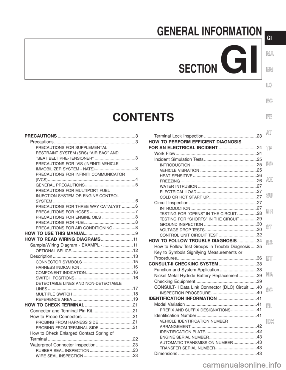
GENERAL INFORMATION
SECTION
GI
CONTENTS
PRECAUTIONS...............................................................3
Precautions ..................................................................3
PRECAUTIONS FOR SUPPLEMENTAL
RESTRAINT SYSTEM (SRS)²AIR BAG²AND
²SEAT BELT PRE-TENSIONER²
.................................3
PRECAUTIONS FOR IVIS (INFINITI VEHICLE
IMMOBILIZER SYSTEM - NATS)
.................................3
PRECAUTIONS FOR INFINITI COMMUNICATOR
(IVCS)
.......................................................................4
GENERAL PRECAUTIONS.........................................5
PRECAUTIONS FOR MULTIPORT FUEL
INJECTION SYSTEM OR ENGINE CONTROL
SYSTEM
...................................................................6
PRECAUTIONS FOR THREE WAY CATALYST...........6
PRECAUTIONS FOR HOSES.....................................7
PRECAUTIONS FOR ENGINE OILS...........................8
PRECAUTIONS FOR FUEL........................................8
PRECAUTIONS FOR AIR CONDITIONING..................8
HOW TO USE THIS MANUAL........................................9
HOW TO READ WIRING DIAGRAMS.......................... 11
Sample/Wiring Diagram - EXAMPL - ........................ 11
OPTIONAL SPLICE..................................................12
Description .................................................................13
CONNECTOR SYMBOLS.........................................15
HARNESS INDICATION...........................................16
COMPONENT INDICATION......................................16
SWITCH POSITIONS...............................................16
DETECTABLE LINES AND NON-DETECTABLE
LINES
.....................................................................17
MULTIPLE SWITCH.................................................18
REFERENCE AREA.................................................19
HOW TO CHECK TERMINAL.......................................21
Connector and Terminal Pin Kit.................................21
How to Probe Connectors .........................................21
PROBING FROM HARNESS SIDE............................21
PROBING FROM TERMINAL SIDE...........................21
How to Check Enlarged Contact Spring of
Terminal .....................................................................22
Waterproof Connector Inspection ..............................23
RUBBER SEAL INSPECTION...................................23
WIRE SEAL INSPECTION........................................23Terminal Lock Inspection ...........................................23
HOW TO PERFORM EFFICIENT DIAGNOSIS
FOR AN ELECTRICAL INCIDENT...............................24
Work Flow ..................................................................24
Incident Simulation Tests ...........................................25
INTRODUCTION......................................................25
VEHICLE VIBRATION..............................................25
HEAT SENSITIVE....................................................26
FREEZING..............................................................26
WATER INTRUSION................................................27
ELECTRICAL LOAD.................................................27
COLD OR HOT START UP.......................................27
Circuit Inspection .......................................................27
INTRODUCTION......................................................27
TESTING FOR²OPENS²IN THE CIRCUIT................28
TESTING FOR²SHORTS²IN THE CIRCUIT..............29
GROUND INSPECTION...........................................30
VOLTAGE DROP TESTS..........................................30
CONTROL UNIT CIRCUIT TEST...............................32
HOW TO FOLLOW TROUBLE DIAGNOSIS................34
How to Follow Test Groups in Trouble Diagnosis .....35
Key to Symbols Signifying Measurements or
Procedures.................................................................36
CONSULT-II CHECKING SYSTEM...............................38
Function and System Application ..............................38
Nickel Metal Hydride Battery Replacement...............39
Checking Equipment..................................................39
CONSULT-II Data Link Connector (DLC) Circuit ......40
INSPECTION PROCEDURE.....................................40
IDENTIFICATION INFORMATION................................41
Model Variation ..........................................................41
PREFIX AND SUFFIX DESIGNATIONS.....................41
Identification Number .................................................41
VEHICLE IDENTIFICATION NUMBER
ARRANGEMENT
.....................................................42
IDENTIFICATION PLATE..........................................42
ENGINE SERIAL NUMBER.......................................43
AUTOMATIC TRANSMISSION NUMBER...................43
TRANSFER SERIAL NUMBER..................................43
Dimensions ................................................................43
MA
EM
LC
EC
FE
AT
TF
PD
AX
SU
BR
ST
RS
BT
HA
SC
EL
IDX
Page 1753 of 2395
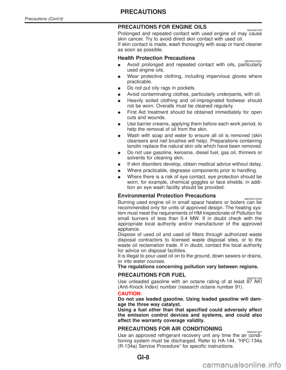
PRECAUTIONS FOR ENGINE OILSNBGI0001S05Prolonged and repeated contact with used engine oil may cause
skin cancer. Try to avoid direct skin contact with used oil.
If skin contact is made, wash thoroughly with soap or hand cleaner
as soon as possible.
Health Protection PrecautionsNBGI0001S0501IAvoid prolonged and repeated contact with oils, particularly
used engine oils.
IWear protective clothing, including impervious gloves where
practicable.
IDo not put oily rags in pockets.
IAvoid contaminating clothes, particularly underpants, with oil.
IHeavily soiled clothing and oil-impregnated footwear should
not be worn. Overalls must be cleaned regularly.
IFirst Aid treatment should be obtained immediately for open
cuts and wounds.
IUse barrier creams, applying them before each work period, to
help the removal of oil from the skin.
IWash with soap and water to ensure all oil is removed (skin
cleansers and nail brushes will help). Preparations containing
lanolin replace the natural skin oils which have been removed.
IDo not use gasoline, kerosine, diesel fuel, gas oil, thinners or
solvents for cleaning skin.
IIf skin disorders develop, obtain medical advice without delay.
IWhere practicable, degrease components prior to handling.
IWhere there is a risk of eye contact, eye protection should be
worn, for example, chemical goggles or face shields; in addi-
tion an eye wash facility should be provided.
Environmental Protection PrecautionsNBGI0001S0502Burning used engine oil in small space heaters or boilers can be
recommended only for units of approved design. The heating sys-
tem must meet the requirements of HM Inspectorate of Pollution for
small burners of less than 0.4 MW. If in doubt check with the
appropriate local authority and/or manufacturer of the approved
appliance.
Dispose of used oil and used oil filters through authorized waste
disposal contractors to licensed waste disposal sites, or to the
waste oil reclamation trade. If in doubt, contact the local authority
for advice on disposal facilities.
It is illegal to pour used oil on to the ground, down sewers or drains,
or into water courses.
The regulations concerning pollution vary between regions.
PRECAUTIONS FOR FUELNBGI0001S06Use unleaded gasoline with an octane rating of at least 87 AKI
(Anti-Knock Index) number (research octane number 91).
CAUTION:
Do not use leaded gasoline. Using leaded gasoline will dam-
age the three way catalyst.
Using a fuel other than that specified could adversely affect
the emission control devices and systems, and could also
affect the warranty coverage validity.
PRECAUTIONS FOR AIR CONDITIONINGNBGI0001S07Use an approved refrigerant recovery unit any time the air condi-
tioning system must be discharged. Refer to HA-144, ªHFC-134a
(R-134a) Service Procedureº for specific instructions.
PRECAUTIONS
Precautions (Cont'd)
GI-8
Page 1802 of 2395
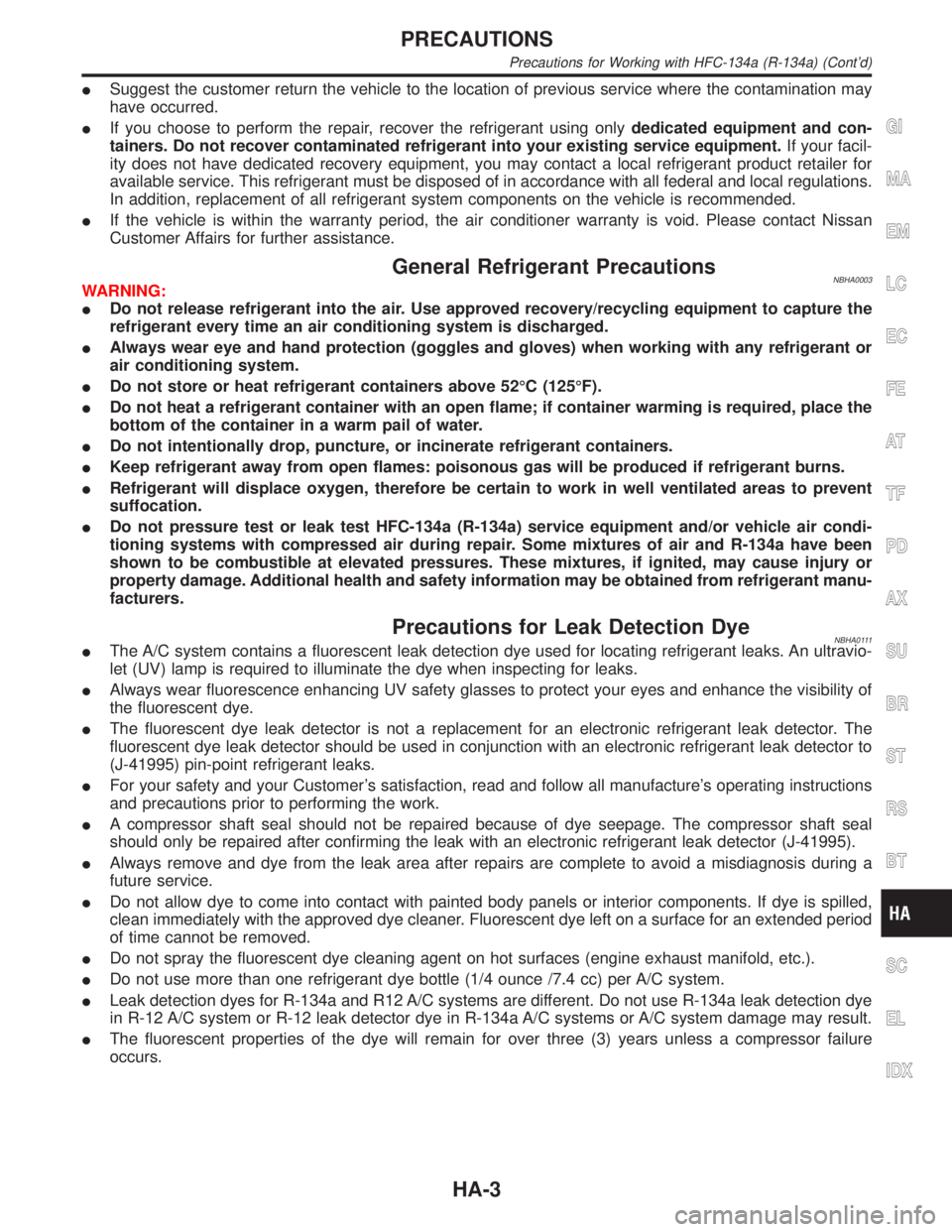
ISuggest the customer return the vehicle to the location of previous service where the contamination may
have occurred.
IIf you choose to perform the repair, recover the refrigerant using onlydedicated equipment and con-
tainers. Do not recover contaminated refrigerant into your existing service equipment.If your facil-
ity does not have dedicated recovery equipment, you may contact a local refrigerant product retailer for
available service. This refrigerant must be disposed of in accordance with all federal and local regulations.
In addition, replacement of all refrigerant system components on the vehicle is recommended.
IIf the vehicle is within the warranty period, the air conditioner warranty is void. Please contact Nissan
Customer Affairs for further assistance.
General Refrigerant PrecautionsNBHA0003WARNING:
IDo not release refrigerant into the air. Use approved recovery/recycling equipment to capture the
refrigerant every time an air conditioning system is discharged.
IAlways wear eye and hand protection (goggles and gloves) when working with any refrigerant or
air conditioning system.
IDo not store or heat refrigerant containers above 52ÉC (125ÉF).
IDo not heat a refrigerant container with an open flame; if container warming is required, place the
bottom of the container in a warm pail of water.
IDo not intentionally drop, puncture, or incinerate refrigerant containers.
IKeep refrigerant away from open flames: poisonous gas will be produced if refrigerant burns.
IRefrigerant will displace oxygen, therefore be certain to work in well ventilated areas to prevent
suffocation.
IDo not pressure test or leak test HFC-134a (R-134a) service equipment and/or vehicle air condi-
tioning systems with compressed air during repair. Some mixtures of air and R-134a have been
shown to be combustible at elevated pressures. These mixtures, if ignited, may cause injury or
property damage. Additional health and safety information may be obtained from refrigerant manu-
facturers.
Precautions for Leak Detection DyeNBHA0111IThe A/C system contains a fluorescent leak detection dye used for locating refrigerant leaks. An ultravio-
let (UV) lamp is required to illuminate the dye when inspecting for leaks.
IAlways wear fluorescence enhancing UV safety glasses to protect your eyes and enhance the visibility of
the fluorescent dye.
IThe fluorescent dye leak detector is not a replacement for an electronic refrigerant leak detector. The
fluorescent dye leak detector should be used in conjunction with an electronic refrigerant leak detector to
(J-41995) pin-point refrigerant leaks.
IFor your safety and your Customer's satisfaction, read and follow all manufacture's operating instructions
and precautions prior to performing the work.
IA compressor shaft seal should not be repaired because of dye seepage. The compressor shaft seal
should only be repaired after confirming the leak with an electronic refrigerant leak detector (J-41995).
IAlways remove and dye from the leak area after repairs are complete to avoid a misdiagnosis during a
future service.
IDo not allow dye to come into contact with painted body panels or interior components. If dye is spilled,
clean immediately with the approved dye cleaner. Fluorescent dye left on a surface for an extended period
of time cannot be removed.
IDo not spray the fluorescent dye cleaning agent on hot surfaces (engine exhaust manifold, etc.).
IDo not use more than one refrigerant dye bottle (1/4 ounce /7.4 cc) per A/C system.
ILeak detection dyes for R-134a and R12 A/C systems are different. Do not use R-134a leak detection dye
in R-12 A/C system or R-12 leak detector dye in R-134a A/C systems or A/C system damage may result.
IThe fluorescent properties of the dye will remain for over three (3) years unless a compressor failure
occurs.
GI
MA
EM
LC
EC
FE
AT
TF
PD
AX
SU
BR
ST
RS
BT
SC
EL
IDX
PRECAUTIONS
Precautions for Working with HFC-134a (R-134a) (Cont'd)
HA-3
Page 1814 of 2395
V-6 Variable Displacement Compressor
GENERAL INFORMATION=NBHA00861. The V-6 variable compressor differs from previous units. The vent temperatures of the V-6 variable com-
press do not drop too far below 5ÉC (41ÉF) when:
Ievaporator intake air temperature is less than 20ÉC (68ÉF)
Iengine is running at speeds less than 1,500 rpm.
This is because the V-6 compressor provides a means of ªcapacityº control.
2. The V-6 variable compressor provides refrigerant control under varying conditions. During cold winters, it
may not produce high refrigerant pressure discharge (compared to previous units) when used with air
conditioning systems.
3. A ªclankingº sound may occasionally be heard during refrigerant charge. The sound indicates that the tilt
angle of the swash plate has changed and is not a problem.
4. For air conditioning systems with the V-6 compressor, the clutch remains engaged unless: the system main
switch, fan switch or ignition switch is turned OFF. When ambient (outside) temperatures are low or when
the amount of refrigerant is insufficient, the clutch is disengaged to protect the compressor.
5. A constant range of suction pressure is maintained when engine speed is greater than a certain value. It
normally ranges from 147 to 177 kPa (1.5 to 1.8 kg/cm
2, 21 to 26 psi) under varying conditions.
In previous compressors, however, suction pressure was reduced with increases in engine speed.
GI
MA
EM
LC
EC
FE
AT
TF
PD
AX
SU
BR
ST
RS
BT
SC
EL
IDX
DESCRIPTION
V-6 Variable Displacement Compressor
HA-15