automatic transmission fluid INFINITI QX4 2001 Factory Service Manual
[x] Cancel search | Manufacturer: INFINITI, Model Year: 2001, Model line: QX4, Model: INFINITI QX4 2001Pages: 2395, PDF Size: 43.2 MB
Page 6 of 2395
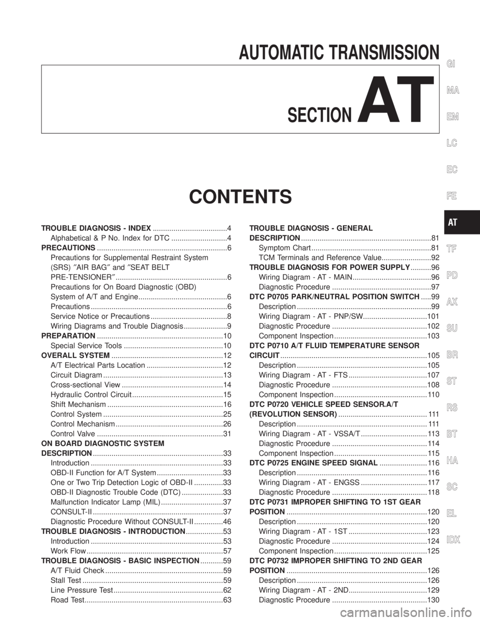
AUTOMATIC TRANSMISSION
SECTION
AT
CONTENTS
TROUBLE DIAGNOSIS - INDEX....................................4
Alphabetical & P No. Index for DTC ...........................4
PRECAUTIONS...............................................................6
Precautions for Supplemental Restraint System
(SRS)²AIR BAG²and²SEAT BELT
PRE-TENSIONER²......................................................6
Precautions for On Board Diagnostic (OBD)
System of A/T and Engine...........................................6
Precautions ..................................................................6
Service Notice or Precautions .....................................8
Wiring Diagrams and Trouble Diagnosis .....................9
PREPARATION.............................................................10
Special Service Tools ................................................10
OVERALL SYSTEM......................................................12
A/T Electrical Parts Location .....................................12
Circuit Diagram ..........................................................13
Cross-sectional View .................................................14
Hydraulic Control Circuit ............................................15
Shift Mechanism ........................................................16
Control System ..........................................................25
Control Mechanism ....................................................26
Control Valve .............................................................31
ON BOARD DIAGNOSTIC SYSTEM
DESCRIPTION...............................................................33
Introduction ................................................................33
OBD-II Function for A/T System ................................33
One or Two Trip Detection Logic of OBD-II ..............33
OBD-II Diagnostic Trouble Code (DTC) ....................33
Malfunction Indicator Lamp (MIL) ..............................37
CONSULT-II ...............................................................37
Diagnostic Procedure Without CONSULT-II ..............46
TROUBLE DIAGNOSIS - INTRODUCTION..................53
Introduction ................................................................53
Work Flow ..................................................................57
TROUBLE DIAGNOSIS - BASIC INSPECTION...........59
A/T Fluid Check .........................................................59
Stall Test ....................................................................59
Line Pressure Test .....................................................62
Road Test...................................................................63TROUBLE DIAGNOSIS - GENERAL
DESCRIPTION...............................................................81
Symptom Chart ..........................................................81
TCM Terminals and Reference Value........................92
TROUBLE DIAGNOSIS FOR POWER SUPPLY..........96
Wiring Diagram - AT - MAIN ......................................96
Diagnostic Procedure ................................................97
DTC P0705 PARK/NEUTRAL POSITION SWITCH.....99
Description .................................................................99
Wiring Diagram - AT - PNP/SW...............................101
Diagnostic Procedure ..............................................102
Component Inspection .............................................103
DTC P0710 A/T FLUID TEMPERATURE SENSOR
CIRCUIT.......................................................................105
Description ...............................................................105
Wiring Diagram - AT - FTS ......................................107
Diagnostic Procedure ..............................................108
Component Inspection ............................................. 110
DTC P0720 VEHICLE SPEED SENSOR.A/T
(REVOLUTION SENSOR)........................................... 111
Description ............................................................... 111
Wiring Diagram - AT - VSSA/T ................................ 113
Diagnostic Procedure .............................................. 114
Component Inspection ............................................. 115
DTC P0725 ENGINE SPEED SIGNAL....................... 116
Description ............................................................... 116
Wiring Diagram - AT - ENGSS ................................ 117
Diagnostic Procedure .............................................. 118
DTC P0731 IMPROPER SHIFTING TO 1ST GEAR
POSITION....................................................................120
Description ...............................................................120
Wiring Diagram - AT - 1ST ......................................123
Diagnostic Procedure ..............................................124
Component Inspection .............................................125
DTC P0732 IMPROPER SHIFTING TO 2ND GEAR
POSITION....................................................................126
Description ...............................................................126
Wiring Diagram - AT - 2ND......................................129
Diagnostic Procedure ..............................................130
GI
MA
EM
LC
EC
FE
TF
PD
AX
SU
BR
ST
RS
BT
HA
SC
EL
IDX
Page 14 of 2395
IThe threads in one or more of the converter bolt holes are damaged.
ITransmission failure did not display evidence of damaged or worn internal parts, steel particles or clutch
plate lining material in unit and inside the fluid filter.
IVehicle has been exposed to high mileage (only). The exception may be where the torque converter clutch
dampener plate lining has seen excess wear by vehicles operated in heavy and/or constant traffic, such
as taxi, delivery or police use.
ATF COOLER SERVICENBAT0004S02Replace ATF cooler if excessive foreign material is found in oil pan or clogging strainer.
Replace radiator lower tank (which includes ATF cooler) with a new one and flush cooler line using cleaning
solvent and compressed air. Refer to LC-19, ªREMOVAL AND INSTALLATIONº.
OBD-II SELF-DIAGNOSISNBAT0004S03IA/T self-diagnosis is performed by the TCM in combination with the ECM. The results can be read through
the blinking pattern of the O/D OFF indicator or the malfunction indicator lamp (MIL). Refer to the table on
AT-38 for the indicator used to display each self-diagnostic result.
IThe self-diagnostic results indicated by the MIL are automatically stored in both the ECM and TCM
memories.
Always perform the procedure ªHOW TO ERASE DTCº on AT-35 to complete the repair and avoid
unnecessary blinking of the MIL.
IThe following self-diagnostic items can be detected using ECM self-diagnostic results mode* only when
the O/D OFF indicator lamp does not indicate any malfunctions.
þ PNP switch
þ A/T 1st, 2nd, 3rd, or 4th gear function
þ A/T TCC S/V function (lock-up)
*: For details of OBD-II, refer to EC-59, ªIntroductionº.
ICertain systems and components, especially those related to OBD, may use the new style slide-
locking type harness connector. For description and how to disconnect, refer to EL-5, ªDescrip-
tionº.
Wiring Diagrams and Trouble DiagnosisNBAT0005When you read wiring diagrams, refer to the following:
IGI-11, ªHOW TO READ WIRING DIAGRAMSº.
IEL-9, ªPOWER SUPPLY ROUTINGº for power distribution circuit.
When you perform trouble diagnosis, refer to the following:
IGI-35, ªHOW TO FOLLOW TEST GROUP IN TROUBLE DIAGNOSISº.
IGI-24, ªHOW TO PERFORM EFFICIENT DIAGNOSIS FOR AN ELECTRICAL INCIDENTº.
GI
MA
EM
LC
EC
FE
TF
PD
AX
SU
BR
ST
RS
BT
HA
SC
EL
IDX
PRECAUTIONS
Service Notice or Precautions (Cont'd)
AT-9
Page 30 of 2395
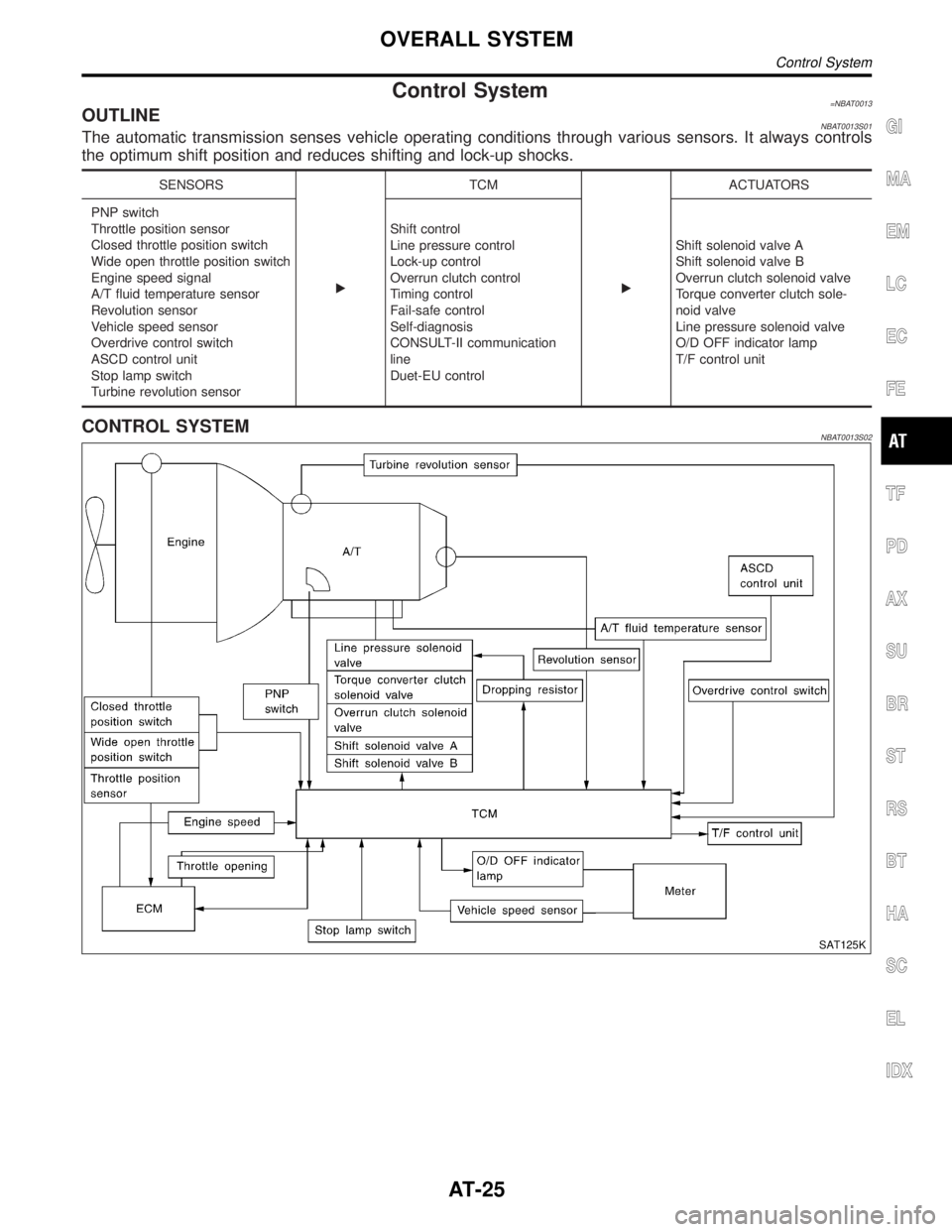
Control System=NBAT0013OUTLINENBAT0013S01The automatic transmission senses vehicle operating conditions through various sensors. It always controls
the optimum shift position and reduces shifting and lock-up shocks.
SENSORS
ETCM
EACTUATORS
PNP switch
Throttle position sensor
Closed throttle position switch
Wide open throttle position switch
Engine speed signal
A/T fluid temperature sensor
Revolution sensor
Vehicle speed sensor
Overdrive control switch
ASCD control unit
Stop lamp switch
Turbine revolution sensorShift control
Line pressure control
Lock-up control
Overrun clutch control
Timing control
Fail-safe control
Self-diagnosis
CONSULT-II communication
line
Duet-EU controlShift solenoid valve A
Shift solenoid valve B
Overrun clutch solenoid valve
Torque converter clutch sole-
noid valve
Line pressure solenoid valve
O/D OFF indicator lamp
T/F control unit
CONTROL SYSTEMNBAT0013S02
SAT125K
GI
MA
EM
LC
EC
FE
TF
PD
AX
SU
BR
ST
RS
BT
HA
SC
EL
IDX
OVERALL SYSTEM
Control System
AT-25
Page 32 of 2395
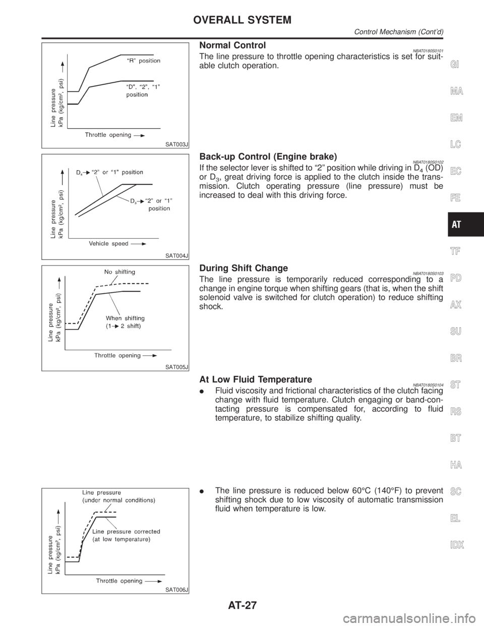
SAT003J
Normal ControlNBAT0180S0101The line pressure to throttle opening characteristics is set for suit-
able clutch operation.
SAT004J
Back-up Control (Engine brake)NBAT0180S0102If the selector lever is shifted to ª2º position while driving in D4(OD)
or D
3, great driving force is applied to the clutch inside the trans-
mission. Clutch operating pressure (line pressure) must be
increased to deal with this driving force.
SAT005J
During Shift ChangeNBAT0180S0103The line pressure is temporarily reduced corresponding to a
change in engine torque when shifting gears (that is, when the shift
solenoid valve is switched for clutch operation) to reduce shifting
shock.
At Low Fluid TemperatureNBAT0180S0104IFluid viscosity and frictional characteristics of the clutch facing
change with fluid temperature. Clutch engaging or band-con-
tacting pressure is compensated for, according to fluid
temperature, to stabilize shifting quality.
SAT006J
IThe line pressure is reduced below 60ÉC (140ÉF) to prevent
shifting shock due to low viscosity of automatic transmission
fluid when temperature is low.
GI
MA
EM
LC
EC
FE
TF
PD
AX
SU
BR
ST
RS
BT
HA
SC
EL
IDX
OVERALL SYSTEM
Control Mechanism (Cont'd)
AT-27
Page 361 of 2395

General SpecificationsNBAT0160
Applied modelVQ35DE engine
2WD 4WD
Automatic transmission model RE4R01A
Transmission model code number 4EX16 4EX17
Stall torque ratio2.0:1
Transmission gear ratio1st 2.785
2nd 1.545
Top 1.000
OD 0.694
Reverse 2.272
Recommended fluidNissan Matic ªDº (Continental U.S. and Alaska) or Genuine Nissan Automatic Trans-
mission Fluid (Canada)*1
Fluid capacity8.5(9 US qt, 7-1/2 Imp qt)
*1: Refer to MA-11, ªFluids and Lubricantsº.
Shift ScheduleNBAT0178VEHICLE SPEED WHEN SHIFTING GEARS THROTTLE POSITIONNBAT0178S01
Throttle positionVehicle speed km/h (MPH)
D
1,D2D2,D3D3,D4D4,D3D3,D2D2,D112,11
Full throttle55-59
(34 - 37)105 - 113
(65 - 70)174 - 184
(108 - 114)170 - 180
(106 - 112)102 - 110
(63 - 68)43-47
(27 - 29)43-47
(27 - 29)
Half throttle37-41
(23 - 25)71-79
(44 - 49)129 - 139
(80 - 86)81-91
(50 - 57)33-41
(21 - 25)12-16
(7 - 10)43-47
(27 - 29)
VEHICLE SPEED WHEN PERFORMING AND RELEASING LOCK-UPNBAT0178S02
Throttle positionOverdrive control switch [Shift posi-
tion]Vehicle speed km/h (MPH)
Lock-up ªONº Lock-up ªOFFº
Full throttleON [D
4] 174 - 184 (108 - 114) 170 - 180 (106 - 112)
OFF [D
3] 104 - 114 (65 - 71) 101 - 111 (63 - 69)
Half throttleON [D
4] 151 - 161 (94 - 100) 106 - 116 (66 - 72)
OFF [D
3] 85-95(53-59) 82-92(51-57)
Stall RevolutionNBAT0163
Stall revolution rpm2,440 - 2,640
Line PressureNBAT0164
Engine speed
rpmLine pressure kPa (kg/cm2, psi)
D, 2 and 1 positions R position
Idle 422 - 461 (4.3 - 4.7, 61 - 67) 667 - 706 (6.8 - 7.2, 97 - 102)
Stall 1,020 - 1,098 (10.4 - 11.2, 148 - 159) 1,422 - 1,500 (14.5 - 15.3, 206 - 218)
SERVICE DATA AND SPECIFICATIONS (SDS)
General Specifications
AT-356
Page 1755 of 2395
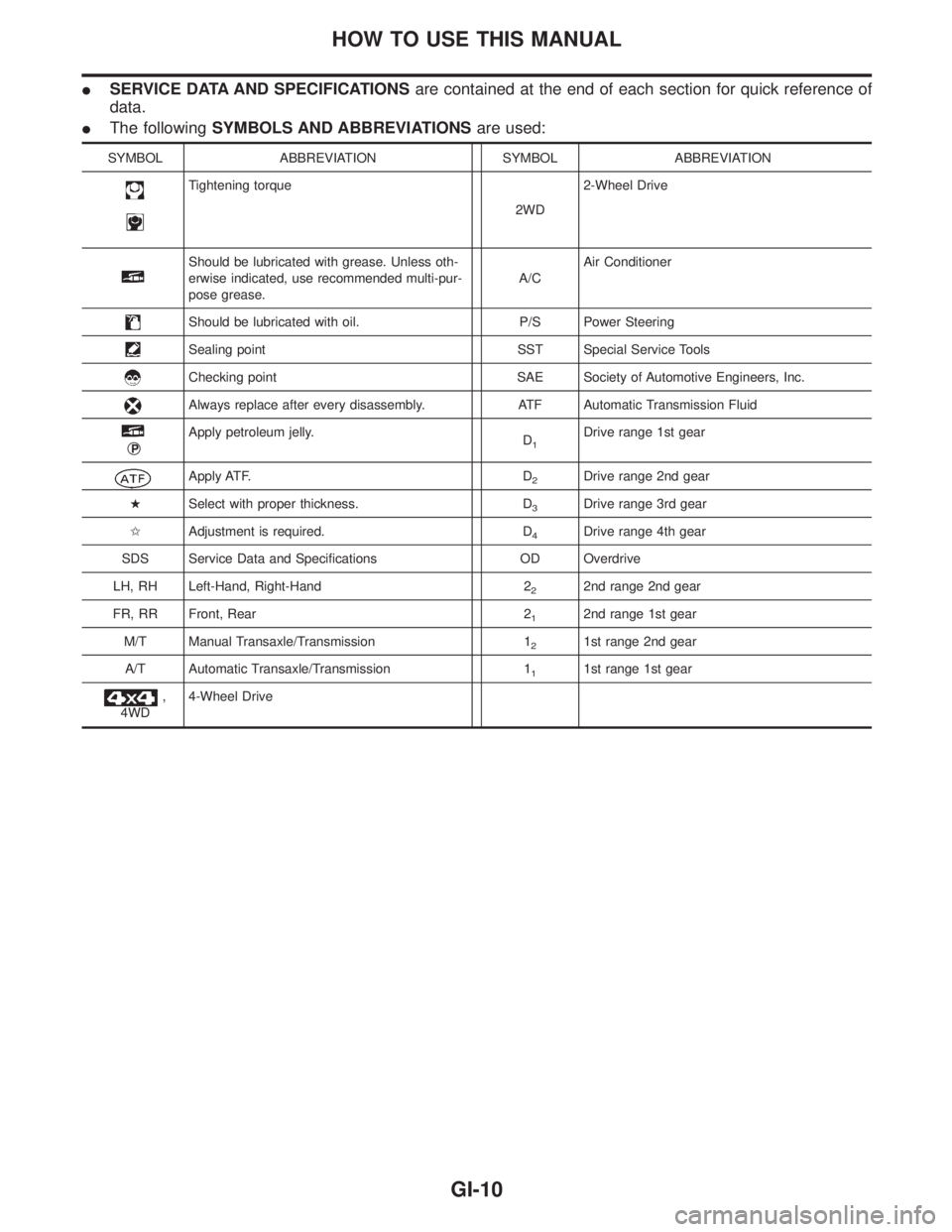
ISERVICE DATA AND SPECIFICATIONSare contained at the end of each section for quick reference of
data.
IThe followingSYMBOLS AND ABBREVIATIONSare used:
SYMBOL ABBREVIATION SYMBOL ABBREVIATION
Tightening torque
2WD2-Wheel Drive
Should be lubricated with grease. Unless oth-
erwise indicated, use recommended multi-pur-
pose grease.A/CAir Conditioner
Should be lubricated with oil. P/S Power Steering
Sealing point SST Special Service Tools
Checking point SAE Society of Automotive Engineers, Inc.
Always replace after every disassembly. ATF Automatic Transmission Fluid
qP
Apply petroleum jelly.
D1Drive range 1st gear
Apply ATF. D2Drive range 2nd gear
HSelect with proper thickness. D
3Drive range 3rd gear
IAdjustment is required. D
4Drive range 4th gear
SDS Service Data and Specifications OD Overdrive
LH, RH Left-Hand, Right-Hand 2
22nd range 2nd gear
FR, RR Front, Rear 2
12nd range 1st gear
M/T Manual Transaxle/Transmission 1
21st range 2nd gear
A/T Automatic Transaxle/Transmission 1
11st range 1st gear
,
4WD4-Wheel Drive
HOW TO USE THIS MANUAL
GI-10
Page 1961 of 2395

A
AAC/V - Wiring diagram ...............................EC-425
ABS - Wiring diagram ....................................BR-37
ABS sensor rotor ........................................AX-6, 19
Absolute pressure sensor ............................EC-158
A/C air flow .....................................................HA-25
A/C component layout ....................................HA-19
A/C compressor clutch removal and
installation .................................................HA-150
A/C compressor precaution..............................HA-6
A/C compressor special service tool..............HA-10
A/C control operation (auto A/C) ....................HA-23
A/C diagnostic work flow (auto A/C) ..............HA-65
A/C HFC134a (R134a) system
precaution .....................................................HA-2
A/C HFC134a (R134a) system service
procedure ..................................................HA-144
A/C HFC134a (R134a) system service
tools.............................................................HA-11
A/C HFC134a system service equip-
ment precaution ............................................HA-7
A/C lubricant (R134a)...................................HA-146
A/C operational check ....................................HA-66
A/C performance chart .................................HA-116
A/C performance test diagnoses ..................HA-114
A/C relay .......................................................HA-110
A/C self-diagnoses (auto A/C)........................HA-44
A/C service data specification ......................HA-160
A/C system description (auto A/C) .................HA-23
A/C trouble diagnoses (auto A/C) ..................HA-27
A/C, A - Wiring diagram ...........................HA-31, 36
Accelerator control system ...............................FE-3
Accelerator wire adjustment .............................FE-3
Actuator lever (Transfer) ...............................TF-120
Air bag ............................................................RS-10
Air bag disposal..............................................RS-22
Air bag precautions ...........................................GI-3
Air bleeding for brake system ..........................BR-8
Air cleaner filter replacement .........................MA-17
Air conditioner cut control ..............................EC-31
Air flow meter - See Mass air flow
sensor .......................................................EC-150
Air mix door control linkage adjustment.........HA-85
Air mix. door motor ................................HA-82, 141
Air spoiler, rear................................................BT-35
All - mode 4WD system ..................................TF-10
Alternator ........................................................SC-28
Ambient sensor ............................................HA-129
Angular tightening application..........................EM-3
Antenna - See Power antenna .....................EL-169
Anti-lock brake system - Wiring
diagram .......................................................BR-37
AP/SEN - Wiring diagram ............................EC-160
ASCD (automatic speed control device) ......EL-221
ASCD - Wiring diagram ................................EL-225
A/T - Wiring diagram - AT - FTS ...................AT-107
A/T - Wiring diagram - AT - MAIN ...................AT-96
A/T - Wiring diagram - AT - PNP/SW............AT-101A/T - Wiring diagram - AT - VSS A/T ............AT-113
A/T control ....................................................EC-440
A/T diagnosis communication line................EC-603
A/T fluid temperature sensor .........................AT-110
A/T self-diagnoses...........................................AT-46
A/T shift lock system .....................................AT-265
A/T shift lock system - Wiring diagram .........AT-266
A/T trouble diagnoses .....................................AT-53
A/T Wiring diagram - AT - ENG SS...............AT-117
A/T Wiring diagram AT - 1ST ........................AT-123
A/T Wiring diagram AT - 2ND .......................AT-129
A/T Wiring diagram AT - 3RD .......................AT-135
A/T Wiring diagram AT - 4TH ........................AT-142
A/T Wiring diagram AT - BA/FTS ..................AT-192
A/T Wiring diagram AT - LPSV .....................AT-164
A/T Wiring diagram AT - NONDTC ...............AT-215
A/T Wiring diagram AT - OVRCSV ...............AT-187
A/T Wiring diagram AT - SSV/A ....................AT-169
A/T Wiring diagram AT - SSV/B ....................AT-173
A/T Wiring diagram AT - TCCSIG .................AT-156
A/T Wiring diagram AT - TCV .......................AT-150
A/T Wiring diagram AT - TPS........................AT-179
A/T Wiring diagram AT - VSSMTR................AT-199
AT/C - Wiring diagram ..................................EC-442
ATP switch.....................................................TF-112
ATP warning lamp .........................................TF-102
Audio .............................................................EL-160
AUDIO - Wiring diagram ...............................EL-162
Audio and A/C control removal and
installation - See Instrument panel .............BT-21
AUT/DP - Wiring diagram .............................EL-191
Auto air conditioner - Wiring diagram ......HA-31, 36
Automatic amplifier...................................HA-40, 72
Automatic drive positioner ............................EL-186
Automatic speed control system - See
ASCD ........................................................EL-221
Automatic transmission fluid
replacement ................................................MA-21
Automatic transmission number ......................GI-43
Auxiliary air control (AAC) valve ..................EC-422
Axle housing (rear) .........................................AX-19
B
Back door ........................................................BT-15
Back door opener - See Back door ................BT-15
Back door trim.................................................BT-34
Back-up lamp ..................................................EL-69
BACK/L - Wiring diagram................................EL-69
Ball joint (front) ...............................................SU-12
Base idle air volume initialiging......................EC-57
Basic inspection ...........................................EC-101
Battery ..............................................................SC-4
Battery/Starting/Charging System
Tester ................................................SC-7, 12, 21
Blower motor ..................................................HA-95
Body alignment ...............................................BT-57
Brake booster .................................................BR-19
Brake control valve (Proportioning
valve)...........................................................BR-11
ALPHABETICAL INDEX
IDX-2
Page 2003 of 2395

CHASSIS AND BODY MAINTENANCENBMA0004S0102
Abbreviations: R = Replace. I = Inspect. Correct or replace if necessary. L = Lubricate
MAINTENANCE OPERATIONMAINTENANCE INTERVAL
Reference
Section
- Page or
- Content Title Perform at number of miles, kilo-
meters or months, whichever
comes first.Miles x 1,000
(km x 1,000)
Months3.75
(6)
37.5
(12)
611.25
(18)
915
(24)
1218.75
(30)
1522.5
(36)
1826.25
(42)
2130
(48)
2433.75
(54)
2737.5
(60)
3041.25
(66)
3345
(72)
3648.75
(78)
3952.5
(84)
4256.25
(90)
4560
(96)
48
Brake lines & cables I I I I MA-25
Brake pads, rotors, drums & linings I IIIIIIIMA-25, 26
Automatic transmission & all-mode
4WD transfer fluid & differential
gear oil (exc. LSD)NOTE (1) I I I I MA-21, 22, 23
LSD gear oil NOTE (1) I R I R MA-24
Steering gear, linkage & transfer
gear, axle & suspension partsIIIIIIIIMA-26
NOTE (6)
Tire rotation NOTE (2)MA-4
Drive shaft boots (
) IIIIIIIIAX-10, ªDrive
Shaftº
Propeller shaft NOTE (3) L LLLLLLLMA-23
Front wheel bearing grease (4x2) I I
Front wheel bearing
grease (
)NOTE (4) I R I RAX-4, ªFront
Wheel Bearingº
Exhaust system I IIIIIIIMA-21
Supplemental air bag systems NOTE (5)RS-14, ªMainte-
nance Itemsº
Ventilation air filter I RIRIRIRHA-159, ªVentila-
tion Air Filterº
ASCD vacuum hoses I I I IEL-237, ªASCD
ACTUATOR/
PUMP CHECKº
NOTE:
(1) If towing a trailer, using a camper or a car-top carrier, or driving on rough or muddy roads, change (not just inspect) fluid (A/T, all mode 4WD transfer)/differential gear oil (exc.
LSD) at every 30,000 miles (48,000 km) or 24 months, and change LSD gear oil every 15,000 miles (24,000 km) or 12 months.
(2) Refer to ªTire rotationº under the ªGENERAL MAINTENANCEº heading earlier in this section.
(3) The propeller shaft should be re-greased after being immersed in water.
(4) If operating frequently in water, replace grease every 3,750 miles (6,000 km) or 3 months.
(5) Inspect the air bag system 10 years after the date of manufacture noted on the FMVSS certification label.
(6) Refer to SU-5, ªFront Suspension Partsº and SU-16, ªRear Suspension Partsº, AX-3, ªFront Axle Partsº and AX-18, ªRear Axle Partsº.
PERIODIC MAINTENANCE
Schedule 1 (Cont'd)
MA-8
Page 2005 of 2395

CHASSIS AND BODY MAINTENANCENBMA0004S0202
Abbreviations: R = Replace. I = Inspect. Correct or replace if necessary. L = Lubricate
MAINTENANCE OPERATIONMAINTENANCE INTERVAL
Reference Section
- Page
or
- Content Title Perform at number of miles, kilometers
or months, whichever comes first.Miles x 1,000
(km x 1,000)
Months7.5
(12)
615
(24)
1222.5
(36)
1830
(48)
2437.5
(60)
3045
(72)
3652.5
(84)
4260
(96)
48
Brake lines & cablesIIIIMA-25
Brake pads, rotors, drums & liningsIIIIMA-25, 26
Automatic transmission & all-mode 4WD
transfer fluid & differential gear oil (exc.
LSD)IIIIMA-21, 22, 23
LSD gear oilIRIRMA-24
Steering gear, linkage & transfer gear,
axle & suspension partsIIMA-26
NOTE (4)
Tire rotation NOTE (1)MA-4
Drive shaft boots (
) IIIIAX-10, ªDrive shaftº
Propeller shaft NOTE (2)LLLLMA-23
Front wheel bearing grease (4x2) I I
Front wheel bearing grease (
) IRIRAX-4, ªFront Wheel
Bearingº
Exhaust systemI I MA-21
Supplemental air bag systems NOTE (3)RS-14, ªMaintenance
Itemº
Ventilation air filterRRRRHA-159, ªVentilation Air
Filterº
ASCD vacuum hosesIIIIEL-237, ªASCD
ACTUATOR/PUMP
CHECKº
NOTE:
(1) Refer to ªTire rotationº under the ªGENERAL MAINTENANCEº heading earlier in this section.
(2) The propeller shaft should be re-greased after being immersed in water.
(3) Inspect the air bag system 10 years after the date of manufacture noted on the FMVSS certification label.
(4) Refer to SU-5, ªFront Suspension Partsº and SU-16, ªRear Suspension Partsº, AX-3, ªFront Axle Partsº and AX-18, ªRear Axle Partsº.
PERIODIC MAINTENANCE
Schedule 2 (Cont'd)
MA-10
Page 2006 of 2395

NBMA0005
Fluids and LubricantsNBMA0005S01
Capacity (Approximate)
Recommended Fluids/Lubricants
US measure Imp measure Liter
Engine oilDrain and
refillWith oil filter 5-1/4 qt 4-3/8 qt 5.0
IAPI Certification Mark*1
IAPI grade SG/SH, Energy Conserv-
ingI&IIorAPIgrade SJ, Energy
Conserving*1
IILSAC grade GF-I & GF-II*1 Without oil
filter5-1/8 qt 4-1/4 qt 4.8
Dry engine
(Engine overhaul)7-1/4 qt 6 qt 6.8
Cooling system (With reservoir) 9-3/4 qt 8-1/8 qt 9.2Genuine Nissan anti-freeze coolant or
equivalent
All-mode 4WD transfer fluid 3-1/8 qt 2-5/8 qt 3.0Nissan Matic ªDº (Continental U.S. and
Alaska) or Canada NISSAN Automatic
Transmission Fluid*2
Differential
carrier gear
oilFront (4WD) 3-7/8 pt 3-1/4 pt 1.85Standard differential gear: API GL-5*1
Limited-slip differential (LSD) gear:
Use only LSD gear oil API GL-5 and
SAE 80W-90*5 approved for Nissan
LSD*6. Rear 5-7/8 pt 4-7/8 pt 2.8
Automatic transmission fluid2WD
9 qt 7-1/2 qt 8.5Nissan Matic ªDº (Continental U.S. and
Alaska) or Canada NISSAN Automatic
Transmission Fluid*3 4WD
Power steering fluid Ð Ð Ð Genuine NISSAN PSF II or equivalent*7
Brake fluid Ð Ð ÐGenuine Nissan Brake Fluid*4 or
equivalent DOT 3 (U.S. FMVSS No.
116)
Propeller shaft grease Ð Ð ÐNLGI No. 2 (Molybdenum disulphide
lithium soap base)
Multi-purpose grease Ð Ð Ð NLGI No. 2 (Lithium soap base)
*1: For further details, see ªSAE Viscosity Numberº.
*2: Outside the continental United States and Alaska contact an authorized INFINITI dealership for more information regarding suitable
fluids, including recommended brand(s) of DEXRON
TMIII/MERCONTMAutomatic Transmission Fluid.
*3: DEXRONTMIII/MERCONTMor equivalent may also be used. Outside the continental United States and Alaska contact an autho-
rized INFINITI dealership for more information regarding suitable fluids, including recommended brand(s) of DEXRONTMIII/MERCONTM
Automatic Transmission Fluid.
*4: Available in mainland U.S.A. through your INFINITI dealer.
*5: SAE 90 is acceptable in ambient temperatures above þ18ÉC (0ÉF).
*6: Contact an INFINITI dealer for a list of approved oils.
*7: Genuine NISSAN PSF, Canada NISSAN Automatic Transmission Fluid, DEXRON
TMIII/MERCONTMor equivalent ATF may also be
used.
GI
EM
LC
EC
FE
AT
TF
PD
AX
SU
BR
ST
RS
BT
HA
SC
EL
IDX
RECOMMENDED FLUIDS AND LUBRICANTS
Fluids and Lubricants
MA-11