fuel filter INFINITI QX4 2001 Factory Service Manual
[x] Cancel search | Manufacturer: INFINITI, Model Year: 2001, Model line: QX4, Model: INFINITI QX4 2001Pages: 2395, PDF Size: 43.2 MB
Page 656 of 2395

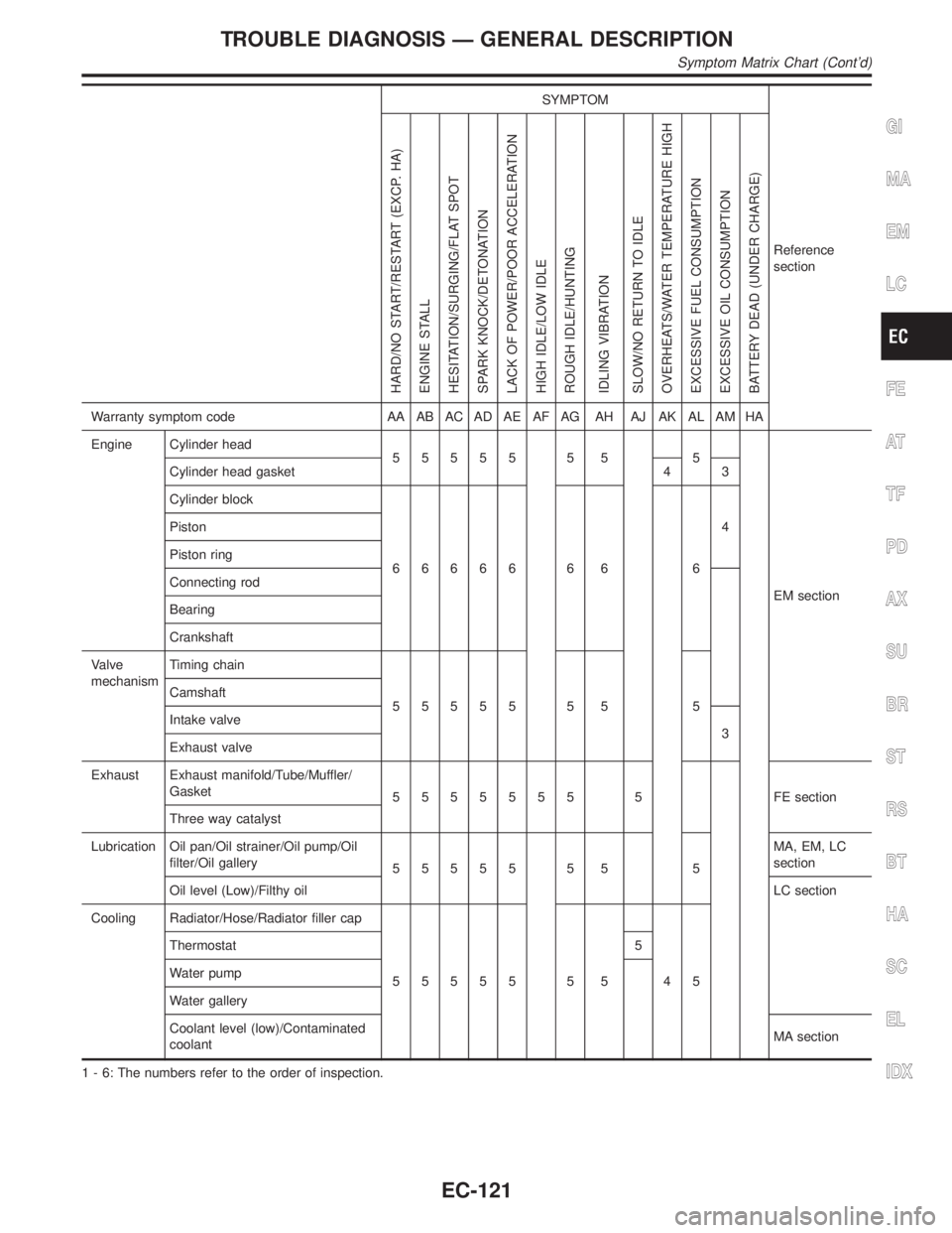
SYMPTOM
Reference
section
HARD/NO START/RESTART (EXCP. HA)
ENGINE STALL
HESITATION/SURGING/FLAT SPOT
SPARK KNOCK/DETONATION
LACK OF POWER/POOR ACCELERATION
HIGH IDLE/LOW IDLE
ROUGH IDLE/HUNTING
IDLING VIBRATION
SLOW/NO RETURN TO IDLE
OVERHEATS/WATER TEMPERATURE HIGH
EXCESSIVE FUEL CONSUMPTION
EXCESSIVE OIL CONSUMPTION
BATTERY DEAD (UNDER CHARGE)
Warranty symptom code AA AB AC AD AE AF AG AH AJ AK AL AM HA
Engine Cylinder head
55555 5 5 5
EM section Cylinder head gasket 4 3
Cylinder block
66666 6 6 64 Piston
Piston ring
Connecting rod
Bearing
Crankshaft
Valve
mechanismTiming chain
55555 5 5 5 Camshaft
Intake valve
3
Exhaust valve
Exhaust Exhaust manifold/Tube/Muffler/
Gasket
5555555 5 FEsection
Three way catalyst
Lubrication Oil pan/Oil strainer/Oil pump/Oil
filter/Oil gallery
55555 5 5 5MA, EM, LC
section
Oil level (Low)/Filthy oilLC section
Cooling Radiator/Hose/Radiator filler cap
55555 5 5 45 Thermostat 5
Water pump
Water gallery
Coolant level (low)/Contaminated
coolantMA section
1 - 6: The numbers refer to the order of inspection.
GI
MA
EM
LC
FE
AT
TF
PD
AX
SU
BR
ST
RS
BT
HA
SC
EL
IDX
TROUBLE DIAGNOSIS Ð GENERAL DESCRIPTION
Symptom Matrix Chart (Cont'd)
EC-121
Page 834 of 2395

4 CHECK FUEL PRESSURE
1. Release fuel pressure to zero. Refer to EC-39.
2. Install fuel pressure gauge and check fuel pressure. Refer to EC-39.
At idling:
When fuel pressure regulator valve vacuum hose is connected.
235 kPa (2.4 kg/cm
2, 34 psi)
When fuel pressure regulator valve vacuum hose is disconnected.
294 kPa (3.0 kg/cm
2, 43 psi)
OK or NG
OK©GO TO 6.
NG©GO TO 5.
5 DETECT MALFUNCTIONING PART
Check the following.
IFuel pump and circuit (Refer to EC-625.)
IFuel pressure regulator (Refer to EC-40.)
IFuel lines (Refer to MA-16, ªChecking Fuel Linesº.)
IFuel filter for clogging
©Repair or replace.
6 CHECK MASS AIR FLOW SENSOR
With CONSULT-II
1. Install all removed parts.
2. Check ªMASS AIR FLOWº in ªDATA MONITORº mode with CONSULT-II.
2.0 - 6.0 g´m/sec: at idling
7.0 - 20.0 g´m/sec: at 2,500 rpm
With GST
1. Install all removed parts.
2. Check mass air flow sensor signal in MODE 1 with GST.
2.0 - 6.0 g´m/sec: at idling
7.0 - 20.0 g´m/sec: at 2,500 rpm
OK or NG
OK©GO TO 7.
NG©Check connectors for rusted terminals or loose connections in the mass air flow sensor
circuit or engine grounds. Refer to EC-150.
GI
MA
EM
LC
FE
AT
TF
PD
AX
SU
BR
ST
RS
BT
HA
SC
EL
IDX
DTC P0171 (RIGHT, -B1), P0174 (LEFT, -B2) FUEL INJECTION SYSTEM
FUNCTION (LEAN)
Diagnostic Procedure (Cont'd)
EC-299
Page 859 of 2395

8 CHECK FUEL PRESSURE
1. Install all removed parts.
2. Release fuel pressure to zero. Refer to EC-39.
3. Install fuel pressure gauge and check fuel pressure. Refer to EC-39.
At idle:
Approx. 235 kPa (2.4 kg/cm
2, 34 psi)
OK or NG
OK©GO TO 10.
NG©GO TO 9.
9 DETECT MALFUNCTIONING PART
Check the following.
IFuel pump and circuit (Refer to EC-625.)
IFuel pressure regulator (Refer to EC-40.)
IFuel lines (Refer to MA-16, ªChecking Fuel Linesº.)
IFuel filter for clogging
©Repair or replace.
10 CHECK IGNITION TIMING
Check the following items. Refer to ªBasic Inspectionº, EC-101.
MTBL0655
OK or NG
OK (With CONSULT-II)©GO TO 11.
OK (Without CONSULT-
II)©GO TO 12.
NG©Follow the ªBasic Inspectionº.
DTC P0300 - P0306 NO.6-1CYLINDER MISFIRE, MULTIPLE CYLINDER
MISFIRE
Diagnostic Procedure (Cont'd)
EC-324
Page 1733 of 2395

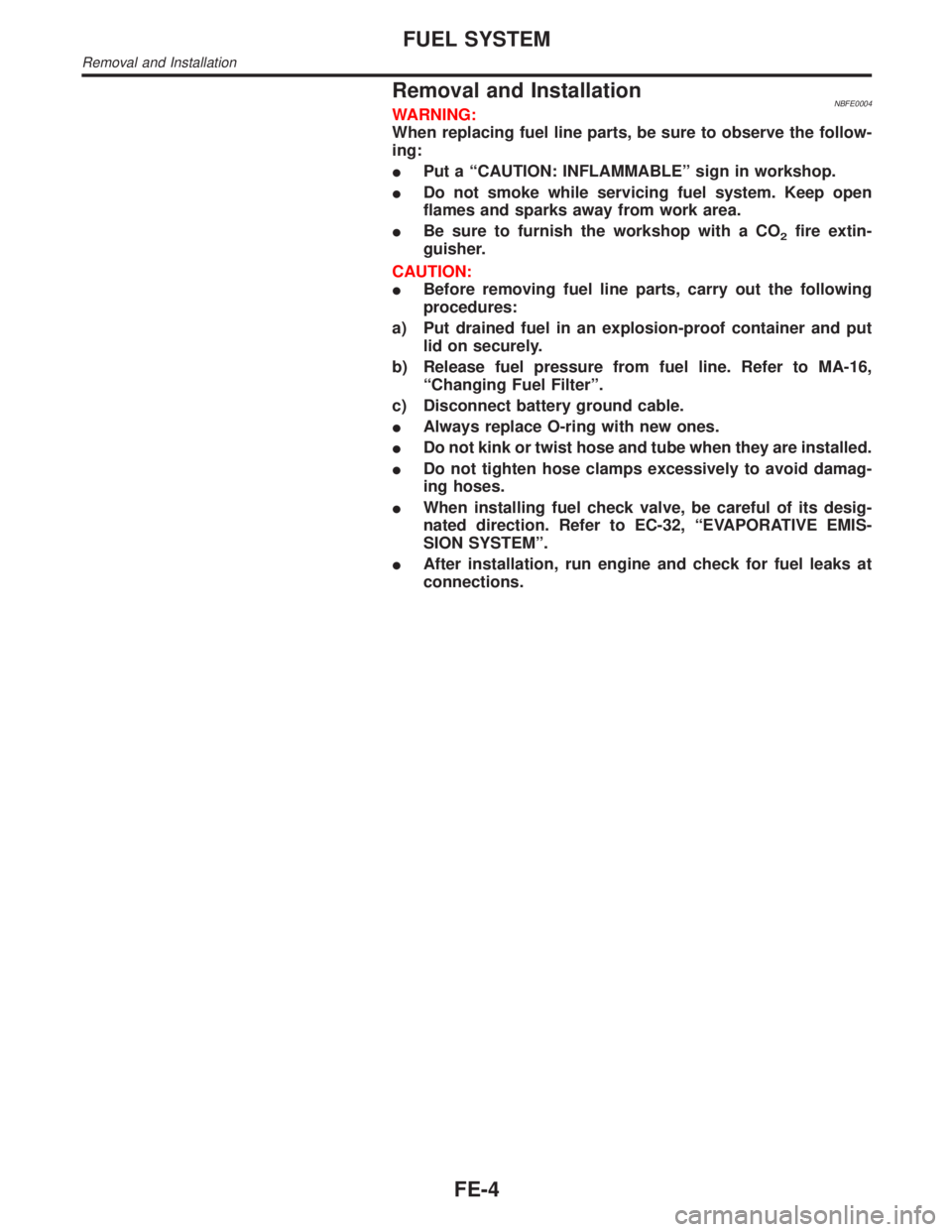
Removal and InstallationNBFE0004WARNING:
When replacing fuel line parts, be sure to observe the follow-
ing:
IPut a ªCAUTION: INFLAMMABLEº sign in workshop.
IDo not smoke while servicing fuel system. Keep open
flames and sparks away from work area.
IBe sure to furnish the workshop with a CO
2fire extin-
guisher.
CAUTION:
IBefore removing fuel line parts, carry out the following
procedures:
a) Put drained fuel in an explosion-proof container and put
lid on securely.
b) Release fuel pressure from fuel line. Refer to MA-16,
ªChanging Fuel Filterº.
c) Disconnect battery ground cable.
IAlways replace O-ring with new ones.
IDo not kink or twist hose and tube when they are installed.
IDo not tighten hose clamps excessively to avoid damag-
ing hoses.
IWhen installing fuel check valve, be careful of its desig-
nated direction. Refer to EC-32, ªEVAPORATIVE EMIS-
SION SYSTEMº.
IAfter installation, run engine and check for fuel leaks at
connections.
FUEL SYSTEM
Removal and Installation
FE-4
Page 1734 of 2395

SFE419AA
SFE420A
FUEL TANKNBFE0004S011. Release fuel pressure from fuel line.
Refer to MA-16, ªChanging Fuel Filterº.
2. Remove inspection hole cover located behind the rear seat.
3. Disconnect harness connectors under inspection hole cover.
4. Disconnect fuel hoses.
IPut mating marks on hoses for correct installation.
SFE468A
5. Disconnect filler hose, vent hose and evaporation hose at fuel
tank side.
GI
MA
EM
LC
EC
AT
TF
PD
AX
SU
BR
ST
RS
BT
HA
SC
EL
IDX
FUEL SYSTEM
Removal and Installation (Cont'd)
FE-5
Page 1735 of 2395

SFE422A
6. Remove parking brake wire from fuel tank protector.
7. Remove fuel tank protector.
SFE469A
8. Remove fuel tank band mounting bolts while supporting fuel
tank.
9. Remove fuel tank.
Installation procedure is the reverse order of removal.
FUEL PUMP AND GAUGENBFE0004S02
SFE541A
1. Release fuel pressure from fuel line.
Refer to MA-16, ªChanging Fuel Filterº.
2. Remove inspection hole cover located behind the rear seat.
3. Disconnect harness connectors and fuel tubes from upper
plate of fuel gauge.
IPut mating marks on tubes for correct installation.
4. Remove fuel gauge retainer and fuel gauge.
FUEL SYSTEM
Removal and Installation (Cont'd)
FE-6
Page 1745 of 2395

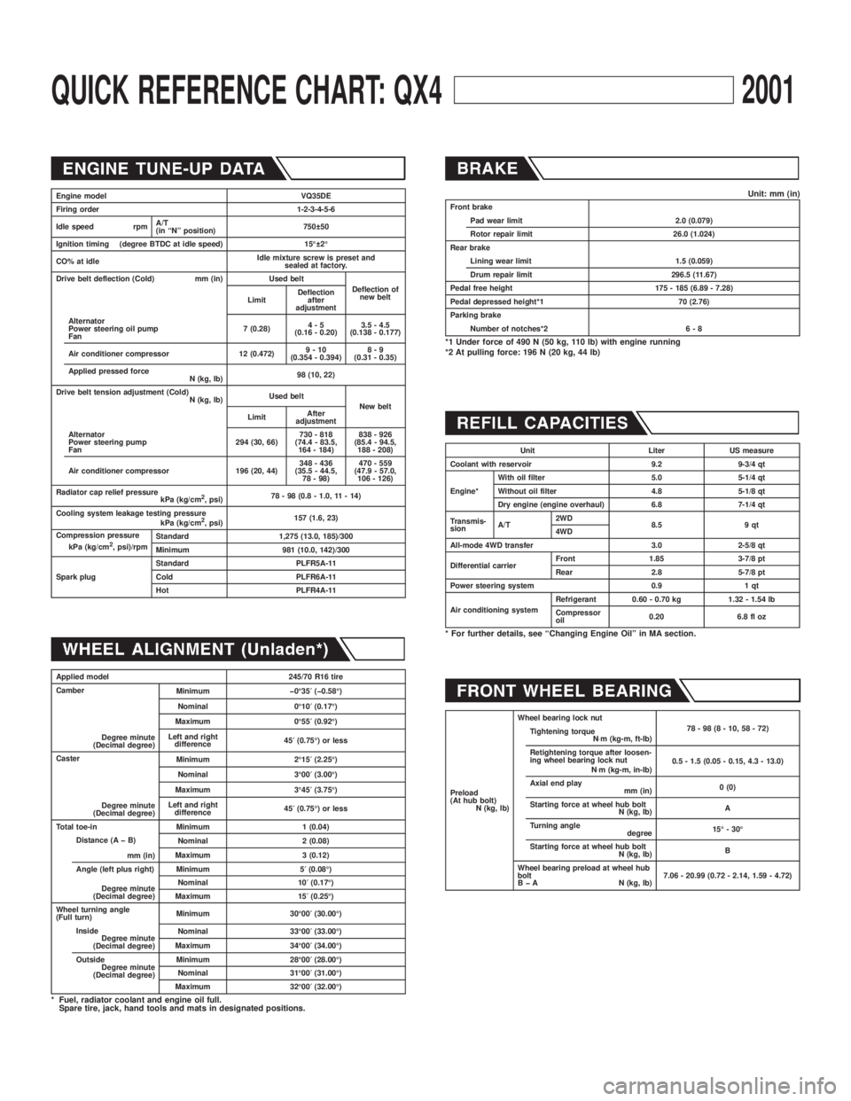
QUICK REFERENCE CHART: QX42001
Engine model VQ35DE
Firing order 1-2-3-4-5-6
Idle speed rpmA/T
(in ªNº position)750 50
Ignition timing (degree BTDC at idle speed) 15É 2É
CO% at idleIdle mixture screw is preset and
sealed at factory.
Drive belt deflection (Cold) mm (in) Used belt
Deflection of
new belt
LimitDeflection
after
adjustment
Alternator
Power steering oil pump
Fan7 (0.28)4-5
(0.16 - 0.20)3.5 - 4.5
(0.138 - 0.177)
Air conditioner compressor 12 (0.472)9-10
(0.354 - 0.394)8-9
(0.31 - 0.35)
Applied pressed force
N (kg, lb)98 (10, 22)
Drive belt tension adjustment (Cold)
N (kg, lb)Used belt
New belt
LimitAfter
adjustment
Alternator
Power steering pump
Fan294 (30, 66)730 - 818
(74.4 - 83.5,
164 - 184)838 - 926
(85.4 - 94.5,
188 - 208)
Air conditioner compressor 196 (20, 44)348 - 436
(35.5 - 44.5,
78 - 98)470 - 559
(47.9 - 57.0,
106 - 126)
Radiator cap relief pressure
kPa (kg/cm
2, psi)78 - 98 (0.8 - 1.0, 11 - 14)
Cooling system leakage testing pressure
kPa (kg/cm
2, psi)157 (1.6, 23)
Compression pressure
kPa (kg/cm
2, psi)/rpmStandard 1,275 (13.0, 185)/300
Minimum 981 (10.0, 142)/300
Spark plugStandard PLFR5A-11
Cold PLFR6A-11
Hot PLFR4A-11
Applied model 245/70 R16 tire
Camber
Degree minute
(Decimal degree)Minimum þ0É35¢(þ0.58É)
Nominal 0É10¢(0.17É)
Maximum 0É55¢(0.92É)
Left and right
difference45¢(0.75É) or less
Caster
Degree minute
(Decimal degree)Minimum 2É15¢(2.25É)
Nominal 3É00¢(3.00É)
Maximum 3É45¢(3.75É)
Left and right
difference45¢(0.75É) or less
Total toe-in Minimum 1 (0.04)
Distance (A þ B)
mm (in)Nominal 2 (0.08)
Maximum 3 (0.12)
Angle (left plus right)
Degree minute
(Decimal degree)Minimum 5¢(0.08É)
Nominal 10¢(0.17É)
Maximum 15¢(0.25É)
Wheel turning angle
(Full turn)Minimum 30É00¢(30.00É)
Inside
Degree minute
(Decimal degree)Nominal 33É00¢(33.00É)
Maximum 34É00¢(34.00É)
Outside
Degree minute
(Decimal degree)Minimum 28É00¢(28.00É)
Nominal 31É00¢(31.00É)
Maximum 32É00¢(32.00É)
* Fuel, radiator coolant and engine oil full.
Spare tire, jack, hand tools and mats in designated positions.
Unit: mm (in)Front brake
Pad wear limit 2.0 (0.079)
Rotor repair limit 26.0 (1.024)
Rear brake
Lining wear limit 1.5 (0.059)
Drum repair limit 296.5 (11.67)
Pedal free height 175 - 185 (6.89 - 7.28)
Pedal depressed height*1 70 (2.76)
Parking brake
Number of notches*2 6 - 8
*1 Under force of 490 N (50 kg, 110 lb) with engine running
*2 At pulling force: 196 N (20 kg, 44 lb)
Unit Liter US measure
Coolant with reservoir 9.2 9-3/4 qt
Engine*With oil filter 5.0 5-1/4 qt
Without oil filter 4.8 5-1/8 qt
Dry engine (engine overhaul) 6.8 7-1/4 qt
Transmis-
sionA/T2WD
8.5 9 qt
4WD
All-mode 4WD transfer 3.0 2-5/8 qt
Differential carrierFront 1.85 3-7/8 pt
Rear 2.8 5-7/8 pt
Power steering system 0.9 1 qt
Air conditioning systemRefrigerant 0.60 - 0.70 kg 1.32 - 1.54 lb
Compressor
oil0.20 6.8 fl oz
* For further details, see ªChanging Engine Oilº in MA section.
Preload
(At hub bolt)
N (kg, lb)Wheel bearing lock nut
78-98(8-10,58-72)
Tightening torque
N×m (kg-m, ft-lb)
Retightening torque after loosen-
ing wheel bearing lock nut
N×m (kg-m, in-lb)0.5 - 1.5 (0.05 - 0.15, 4.3 - 13.0)
Axial end play
mm (in)0 (0)
Starting force at wheel hub bolt
N (kg, lb)A
Turning angle
degree15É - 30É
Starting force at wheel hub bolt
N (kg, lb)B
Wheel bearing preload at wheel hub
bolt
B þ A N (kg, lb)7.06 - 20.99 (0.72 - 2.14, 1.59 - 4.72)
Page 1753 of 2395

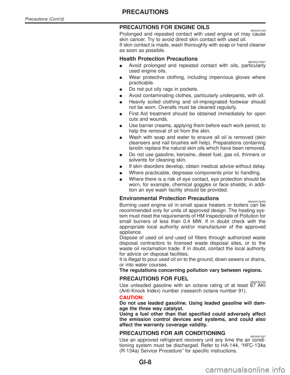
PRECAUTIONS FOR ENGINE OILSNBGI0001S05Prolonged and repeated contact with used engine oil may cause
skin cancer. Try to avoid direct skin contact with used oil.
If skin contact is made, wash thoroughly with soap or hand cleaner
as soon as possible.
Health Protection PrecautionsNBGI0001S0501IAvoid prolonged and repeated contact with oils, particularly
used engine oils.
IWear protective clothing, including impervious gloves where
practicable.
IDo not put oily rags in pockets.
IAvoid contaminating clothes, particularly underpants, with oil.
IHeavily soiled clothing and oil-impregnated footwear should
not be worn. Overalls must be cleaned regularly.
IFirst Aid treatment should be obtained immediately for open
cuts and wounds.
IUse barrier creams, applying them before each work period, to
help the removal of oil from the skin.
IWash with soap and water to ensure all oil is removed (skin
cleansers and nail brushes will help). Preparations containing
lanolin replace the natural skin oils which have been removed.
IDo not use gasoline, kerosine, diesel fuel, gas oil, thinners or
solvents for cleaning skin.
IIf skin disorders develop, obtain medical advice without delay.
IWhere practicable, degrease components prior to handling.
IWhere there is a risk of eye contact, eye protection should be
worn, for example, chemical goggles or face shields; in addi-
tion an eye wash facility should be provided.
Environmental Protection PrecautionsNBGI0001S0502Burning used engine oil in small space heaters or boilers can be
recommended only for units of approved design. The heating sys-
tem must meet the requirements of HM Inspectorate of Pollution for
small burners of less than 0.4 MW. If in doubt check with the
appropriate local authority and/or manufacturer of the approved
appliance.
Dispose of used oil and used oil filters through authorized waste
disposal contractors to licensed waste disposal sites, or to the
waste oil reclamation trade. If in doubt, contact the local authority
for advice on disposal facilities.
It is illegal to pour used oil on to the ground, down sewers or drains,
or into water courses.
The regulations concerning pollution vary between regions.
PRECAUTIONS FOR FUELNBGI0001S06Use unleaded gasoline with an octane rating of at least 87 AKI
(Anti-Knock Index) number (research octane number 91).
CAUTION:
Do not use leaded gasoline. Using leaded gasoline will dam-
age the three way catalyst.
Using a fuel other than that specified could adversely affect
the emission control devices and systems, and could also
affect the warranty coverage validity.
PRECAUTIONS FOR AIR CONDITIONINGNBGI0001S07Use an approved refrigerant recovery unit any time the air condi-
tioning system must be discharged. Refer to HA-144, ªHFC-134a
(R-134a) Service Procedureº for specific instructions.
PRECAUTIONS
Precautions (Cont'd)
GI-8
Page 1963 of 2395

E
ECM input/output signal ...............................EC-127
ECTS - Wiring diagram ........................EC-171, 189
Electric sun roof ............................................EL-173
Electrical diagnoses.........................................GI-24
Electrical ignition system ................................EC-30
Electrical unit ................................................Foldout
Electrical units location .................................EL-436
Engine compartment .......................................BT-58
Engine control circuit diagram........................EC-24
Engine control component parts
location .......................................................EC-20
Engine control module (ECM) ......................EC-444
Engine control system diagram and
chart ............................................................EC-25
Engine coolant temperature sensor
(ECTS) ..............................................EC-169, 187
Engine fail-safe system ................................EC-117
Engine oil filter replacement ..........................MA-18
Engine oil precautions .......................................GI-8
Engine oil replacement ..................................MA-18
Engine outer component parts ......................EM-10
Engine removal ..............................................EM-57
Engine room - See Engine
compartment................................................BT-58
Engine serial number ......................................GI-43
EVAP canister.................................................EC-33
EVAP canister purge volume control
solenoid valve.............................EC-32, 367, 541
EVAP canister vent control
valve .........................................EC-374, 553, 573
EVAP control system (small leak)
diagnosis ..................................EC-352, 394, 526
EVAP control system pressure sensor.........EC-381
EVAP control system purge flow moni-
toring diagnosis.........................................EC-561
EVAP vapor lines inspection ..........................MA-20
Evaporative emission (EVAP) system ............EC-32
Exhaust system ................................................FE-8
Exhaust system inspection ............................MA-21
Exterior ............................................................BT-35
F
4LO indicator lamp........................................TF-104
4WD shift indicator lamp.................................TF-98
4WD shift switch ............................................TF-111
4WD solenoid valve.......................................TF-111
4WD warning lamp .........................................TF-13
Fan control amp. ............................................HA-98
F/FOG - Wiring diagram .................................EL-72
Final drive disassembly ..................................PD-43
Final drive pre-inspection ...............................PD-43
Final drive removal and installation ...............PD-43
Finisher, interior - See Trim ............................BT-28
F/LID - Wiring diagram .................................EL-180
Fluid temperature sensor (A/T) .....................AT-110Fluids ..............................................................MA-11
Flywheel runout..............................................EM-70
FO2H-L - Wiring diagram .............................EC-243
FO2H-R - Wiring diagram ............................EC-242
Fog lamp, front................................................EL-70
Fog lamp, front, removal and
installation ...................................................BT-12
Forward clutch ...............................................AT-320
F/PUMP - Wiring diagram ............................EC-627
Freeze frame data ..........................................EC-60
FRO2LH - Wiring diagram ...........EC-197, 223, 235
FRO2RH - Wiring diagram...........EC-196, 222, 234
Front axle..........................................................AX-2
Front bumper ..................................................BT-12
Front case (Transfer) ....................................TF-133
Front combination lamp removal and
installation ...................................................BT-12
Front disc brake .............................................BR-22
Front door .......................................................BT-18
Front drive shaft (Transfer) ...........................TF-125
Front final drive disassembly (4WD) ..............PD-18
Front final drive pre-inspection (4WD) ...........PD-18
Front final drive removal and installa-
tion (4WD)...................................................PD-18
Front fog lamp.................................................EL-70
Front fog lamp removal and installation .........BT-12
Front heated oxygen sensor (HO2S)
(Left bank) ................EC-192, 202, 210, 218, 231
Front heated oxygen sensor (HO2S)
(Right bank) .............EC-192, 202, 210, 218, 231
Front heated oxygen sensor heater
(Left bank).................................................EC-240
Front heated oxygen sensor heater
(Right bank) ..............................................EC-240
Front revolution sensor (Transfer) ................TF-112
Front seat ........................................................BT-41
Front seat belt ..................................................RS-4
Front suspension ..............................................SU-2
Front washer .................................................EL-136
Front wiper ....................................................EL-136
Fuel cut control (at no load & high
engine speed) .............................................EC-32
Fuel filler lid.....................................................BT-15
Fuel filter replacement ...................................MA-16
Fuel gauge ......................................................EL-94
Fuel injection system (Left bank) .........EC-294, 302
Fuel injection system (Right bank) ......EC-294, 302
Fuel lid opener, electric.................................EL-180
Fuel line inspection ........................................MA-16
Fuel precautions ................................................GI-8
Fuel pressure check .......................................EC-39
Fuel pressure regulator ..................................EC-40
Fuel pressure release ....................................EC-39
Fuel pump ....................................................EC-625
Fuel system ......................................................FE-4
Fuel tank temperature sensor ......................EC-309
Fuel tank vacuum relief valve ........................EC-33
FUELLH - Wiring diagram....................EC-297, 305
FUELRH - Wiring diagram ...................EC-296, 304
Fuse ................................................................EL-16
Fuse block ....................................................Foldout
ALPHABETICAL INDEX
IDX-4
Page 1965 of 2395

LSV (Load sensing valve) ..............................BR-12
Lubricant (R134a) A/C..................................HA-146
Lubricants .......................................................MA-11
Lubrication circuit (engine) ...............................LC-3
Lubrication-locks, hinges and hood
latches ........................................................MA-27
Luggage room lamp ........................................EL-88
M
MAFS - Wiring diagram................................EC-154
Magnet clutch .......................................HA-104, 150
MAIN - Wiring diagram.................................EC-142
Main oil pump (Transfer)...............................TF-131
Mainshaft (Transfer) ......................................TF-125
Maintenance (engine) ....................................MA-13
MAJOR OVERHALL......................................AT-281
Major overhaul (Transfer) .............................TF-120
Malfunction indicator lamp (MIL) ....................EC-74
Mass air flow sensor (MAFS) .......................EC-150
Master cylinder (brake) ..................................BR-16
Meter ...............................................................EL-94
METER - Wiring diagram................................EL-99
MIL & Data link connectors circuit ...............EC-648
MIL/DL - Wiring diagram ..............................EC-648
MIRROR - Wiring diagram............................EL-177
Mirror defogger .............................................EL-151
Mirror, door......................................................BT-56
Mirror, out side ................................................BT-56
Misfire ...........................................................EC-320
Mode door control linkage adjustment ...........HA-81
Mode door motor ............................................HA-75
Model variation ................................................GI-41
Molding - See Exterior ....................................BT-35
MULTI - Wiring diagram ................................EL-274
Multi-remote control system..........................EL-270
Multiplex communication ..............................HA-142
Multiport fuel injection (MFI) system ..............EC-28
Multiport fuel injection precautions ....................GI-6
N
NATS (Nissan anti-theft system)...................EL-328
NATS (Nissan anti-theft system)
precautions ....................................................GI-3
NATS - Wiring diagram .................................EL-330
NAVI - wiring diagram ...................................EL-394
Navigation System ........................................EL-385
Neutral-4LO switch ........................................TF-112
NVH troubleshooting (AX) ..........................AX-3, 18
NVH troubleshooting (BR)................................BR-6
NVH troubleshooting (PD)................................PD-3
NVH troubleshooting (ST).................................ST-6
NVH troubleshooting (SU) .........................SU-3, 15O
Oil change (capacity) .....................................MA-11
Oil filter (Transfer) .........................................TF-118
Oil pan (engine) .............................................EM-15
Oil pressure (engine) ........................................LC-4
Oil pump (A/T) ...............................................AT-297
Oil pump (engine) .............................................LC-5
Oil pump regulator valve (engine) ....................LC-6
Oil seal replacement (engine)........................EM-35
Oil seal replacement (front final drive
4WD) ...........................................................PD-15
Oil seal replacement (front of final
drive) ...........................................................PD-40
On board diagnostic system ..........................EC-59
Out side mirror ................................................BT-56
Overdrive control switch ................................AT-263
Overrun clutch ...............................................AT-320
Overrun clutch solenoid valve .......................AT-189
P
P/ANT - Wiring diagram ................................EL-170
Park/Neutral position switch .........................EC-604
Park/neutral position switch (A/T) .........AT-103, 263
Parking brake control .....................................BR-30
Parking lamp ...................................................EL-61
PCV (positive crankcase ventilation) .............EC-38
PGC/V - Wiring diagram ......................EC-370, 544
PHASE - Wiring diagram .............................EC-342
Pinion bearing preload diff. ............................PD-25
Pinion gear height diff. .............................PD-25, 53
Piston assembly .............................................EM-71
Piston pin inspection ......................................EM-63
Piston ring inspection.....................................EM-64
Piston to bore clearance ................................EM-66
Planetary carrier (Transfer) ...........................TF-134
PNP/SW - Wiring diagram ...........................EC-607
POS - Wiring diagram ..................................EC-517
POWER - Wiring diagram...............................EL-10
Power antenna ..............................................EL-169
Power door lock ............................................EL-254
Power door mirror .........................................EL-177
Power seat ....................................................EL-181
Power steering fluid level .....................MA-27, ST-8
Power steering gear........................................ST-17
Power steering hydraulic pressure .................ST-10
Power steering oil pressure switch ..............EC-634
Power steering oil pump .................................ST-27
Power steering system bleeding.......................ST-9
Power supply routing ........................................EL-9
Power transistor & ignition coil.....................EC-499
Power window ...............................................EL-241
PRE/SE - Wiring diagram ............................EC-384
Precations for Leak detection dye ...................HA-3
Precautions (General) .......................................GI-5
Pressure test (A/T) ..........................................AT-62
Propeller shaft ..................................................PD-3
ALPHABETICAL INDEX
IDX-6