towing INFINITI QX4 2001 Factory Service Manual
[x] Cancel search | Manufacturer: INFINITI, Model Year: 2001, Model line: QX4, Model: INFINITI QX4 2001Pages: 2395, PDF Size: 43.2 MB
Page 1700 of 2395
Removal and InstallationNBEM0042WARNING:
ISituate vehicle on a flat and solid surface.
IPlace chocks at front and back of rear wheels.
IDo not remove engine until exhaust system has com-
pletely cooled off. Otherwise, you may burn yourself
and/or fire may break out in fuel line.
IFor safety during subsequent steps, the tension of wires
should be slackened against the engine.
IBefore disconnecting fuel hose, release fuel pressure
from fuel line.
Refer to EC-39, ªFuel Pressure Releaseº.
IBefore removing front axle from transmission, place
safety stands under designated front supporting points.
Refer to GI section for lifting points and towing.
IBe sure to hoist engine and transmission in a safe man-
ner.
IFor engines not equipped with engine slingers, attach
proper slingers and bolts described in PARTS CATALOG.
CAUTION:
IWhen lifting engine, be careful not to strike adjacent parts,
especially accelerator wire casing, brake lines, and brake
master cylinder.
IIn hoisting the engine, always use engine slingers in a
safe manner.
IBefore separating engine and transmission, remove
crankshaft position sensor (POS) from the assembly.
IAlways take extra care not to damage edge of crankshaft
position sensor (POS), or ring gear teeth.GI
MA
LC
EC
FE
AT
TF
PD
AX
SU
BR
ST
RS
BT
HA
SC
EL
IDX
ENGINE ASSEMBLY
Removal and Installation
EM-57
Page 1747 of 2395

Wheels & Tires ..........................................................44
LIFTING POINTS AND TOW TRUCK TOWING...........45
Screw Jack ................................................................45
Garage Jack and Safety Stand .................................46
2-pole Lift ...................................................................47
Tow Truck Towing ......................................................472WD MODELS.........................................................48
4WD MODELS.........................................................48
VEHICLE RECOVERY..............................................49
TIGHTENING TORQUE OF STANDARD BOLTS........50
SAE J1930 TERMINOLOGY LIST................................51
SAE J1930 Terminology List .....................................51
CONTENTS(Cont'd)
GI-2
Page 1790 of 2395

NBGI0008
WARNING:
INever get under the vehicle while it is supported only by
the jack. Always use safety stands to support the frame
when you have to get under the vehicle.
IPlace wheel chocks at both front and back of the wheels
on the ground.
Screw JackNBGI0008S01
SGI927
MA
EM
LC
EC
FE
AT
TF
PD
AX
SU
BR
ST
RS
BT
HA
SC
EL
IDX
LIFTING POINTS AND TOW TRUCK TOWING
GI-45
Page 1791 of 2395

Garage Jack and Safety Stand=NBGI0008S02CAUTION:
Place a wooden or rubber block between safety stand and
vehicle body when the supporting body is flat.
SGI132A
LIFTING POINTS AND TOW TRUCK TOWING
Garage Jack and Safety Stand
GI-46
Page 1792 of 2395
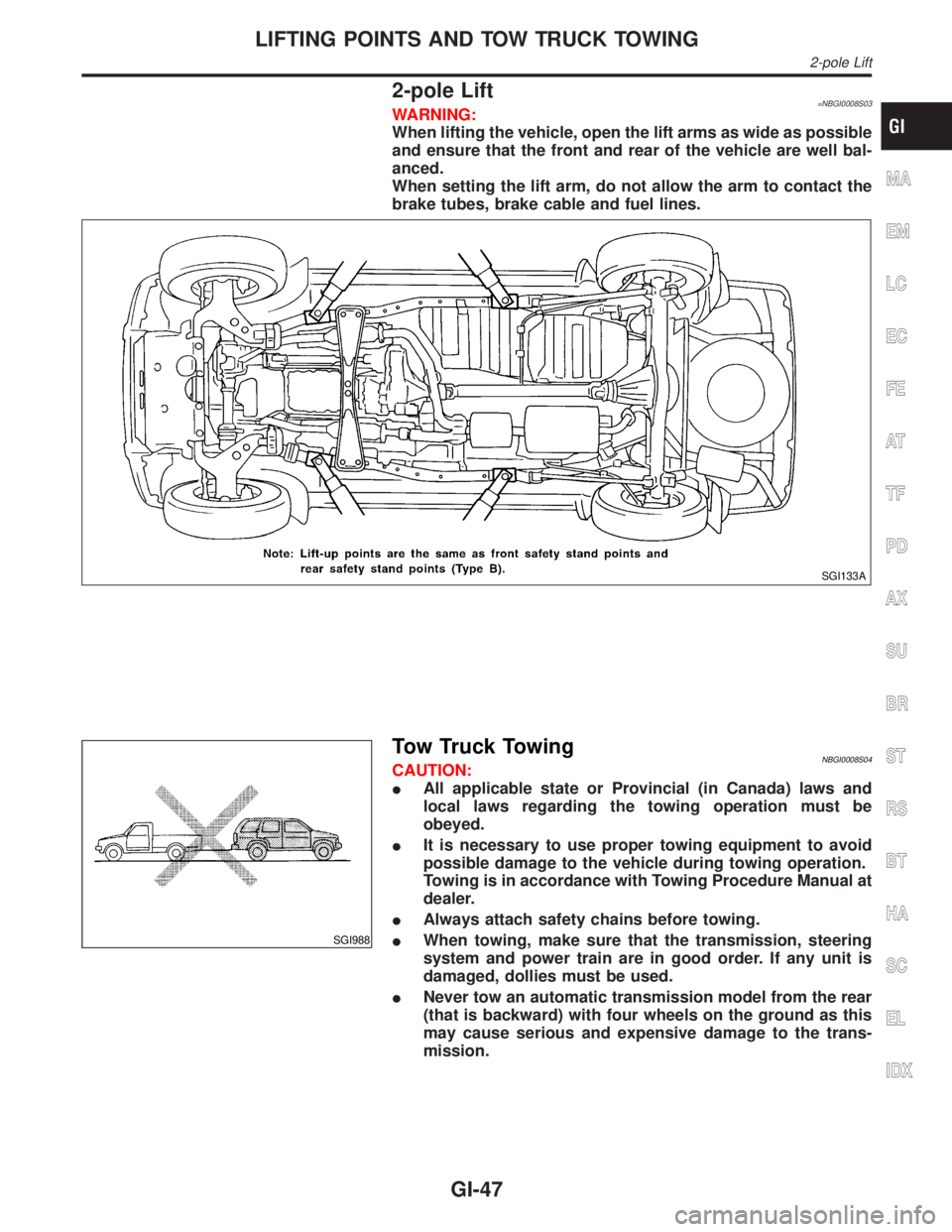
2-pole Lift=NBGI0008S03WARNING:
When lifting the vehicle, open the lift arms as wide as possible
and ensure that the front and rear of the vehicle are well bal-
anced.
When setting the lift arm, do not allow the arm to contact the
brake tubes, brake cable and fuel lines.
SGI133A
SGI988
Tow Truck TowingNBGI0008S04CAUTION:
IAll applicable state or Provincial (in Canada) laws and
local laws regarding the towing operation must be
obeyed.
IIt is necessary to use proper towing equipment to avoid
possible damage to the vehicle during towing operation.
Towing is in accordance with Towing Procedure Manual at
dealer.
IAlways attach safety chains before towing.
IWhen towing, make sure that the transmission, steering
system and power train are in good order. If any unit is
damaged, dollies must be used.
INever tow an automatic transmission model from the rear
(that is backward) with four wheels on the ground as this
may cause serious and expensive damage to the trans-
mission.
MA
EM
LC
EC
FE
AT
TF
PD
AX
SU
BR
ST
RS
BT
HA
SC
EL
IDX
LIFTING POINTS AND TOW TRUCK TOWING
2-pole Lift
GI-47
Page 1793 of 2395

SGI989
2WD MODELSNBGI0008S0402INFINITI recommends that vehicle be towed with the driving (rear)
wheels off the ground as illustrated.
CAUTION:
IWhen towing manual or automatic transmission models
with the front wheels on the ground: Turn the ignition key
to the OFF position and secure the steering wheel in a
straightahead position with a rope or similar device. Never
place the ignition key in the LOCK position. This will result
in damage to the steering lock mechanism.
IWhen towing manual transmission models with the rear
wheels on the ground or four wheels on the ground (if you
do not use towing dollies): Always release the parking
brake and move the transmission shift lever to the N (neu-
tral) position.
Observe the following restricted towing speeds and distances.
Manual transmission models:
ISpeed: Below 95 km/h (60 MPH)
IDistance: Less than 800 km (500 miles)
If the speed or distance must necessarily be greater, remove the
propeller shaft beforehand to prevent damage to the transmission.
SGI950
4WD MODELSNBGI0008S0403INFINITI recommends that a dolly or a flat bed truck be used as
illustrated when towing all-mode 4WD models.
LIFTING POINTS AND TOW TRUCK TOWING
Tow Truck Towing (Cont'd)
GI-48
Page 1794 of 2395
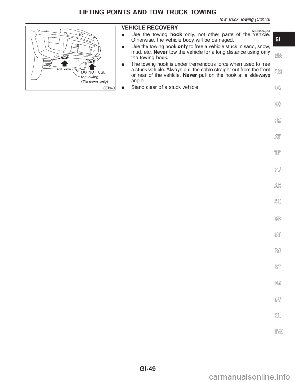
SGI949
VEHICLE RECOVERYNBGI0008S0401IUse the towinghookonly, not other parts of the vehicle.
Otherwise, the vehicle body will be damaged.
IUse the towing hookonlyto free a vehicle stuck in sand, snow,
mud, etc.Nevertow the vehicle for a long distance using only
the towing hook.
IThe towing hook is under tremendous force when used to free
a stuck vehicle. Always pull the cable straight out from the front
or rear of the vehicle.Neverpull on the hook at a sideways
angle.
IStand clear of a stuck vehicle.
MA
EM
LC
EC
FE
AT
TF
PD
AX
SU
BR
ST
RS
BT
HA
SC
EL
IDX
LIFTING POINTS AND TOW TRUCK TOWING
Tow Truck Towing (Cont'd)
GI-49
Page 1967 of 2395
S/VCSW - Wiring diagram ...........................EC-493
Swirl control valve control solenoid
valve .........................................................EC-458
Swirl control valve control vacuum
check switch .............................................EC-493
SWL/V - Wiring diagram ..............................EC-458
Symbols and abbreviations .............................GI-10
Symptom matrix chart...................................EC-118
System readiness test (SRT) code ................EC-61
T
2-4WD shift solenoid valve............................TF-111
Tachometer .....................................................EL-94
Tail lamp ..........................................................EL-61
TAIL/L - Wiring diagram ..................................EL-63
TCM circuit diagram ........................................AT-13
TCM inspection table ......................................AT-92
TFTS - Wiring diagram .................................EC-311
THEFT - Wiring diagram ...............................EL-300
Theft warning system....................................EL-294
Thermometer .................................................EL-110
Thermostat ......................................................LC-16
Three way catalyst function (Left bank) .......EC-347
Three way catalyst function (Right
bank) .........................................................EC-347
Three way catalyst precautions.........................GI-6
Throttle bodies ...............................................EM-12
Throttle position sensor (TPS) .....................EC-174
Throttle position sensor adjustment .............EC-101
Throttle position switch ...........EC-431, AT-184, 264
Tie-rod .............................................................ST-21
Tie-rod ball joints.............................................ST-21
Tightening torque of standard bolts.................GI-50
Timing chain ...................................................EM-20
Tire rotation ....................................................MA-24
Tire size ...........................................................GI-44
TLID - Wiring diagram ..................................EL-179
Tooth contact (front final drive 4WD) .............PD-29
Tooth contact diff. ...........................................PD-56
Torque converter installation .........................AT-278
Torque convertor clutch solenoid
valve ..................................................AT-152, 161
Tow truck towing ..............................................GI-47
Towing point.....................................................GI-49
TP/SW - Wiring diagram ..............................EC-434
TPS - Wiring diagram...................................EC-180
Transfer control unit inspection table..............TF-55
Transfer dropping resistor .............................TF-112
Transfer fluid replacement (Part time
4WD model) ...............................................MA-22
Transfer fluid temperature sensor .................TF-111
Transfer motor ...............................................TF-117
Transfer motor relay ......................................TF-113
Transfer serial number ....................................GI-43
TRANSMT - Wiring diagram .........................EL-325
Tread-FR&RR (Dimensions)............................GI-43
Trim .................................................................BT-28
Trouble diagnoses ...........................................GI-34
Trunk lid opener, electric...............................EL-178Turbine revolution sensor..............................AT-202
TURN - Wiring diagram ..................................EL-77
Turn signal lamp .............................................EL-75
Two trip detection logic ..................................EC-59
Two-pole lift .....................................................GI-47
U
Under body .....................................................BT-60
V
Vacuum cut valve ...........................................EC-32
Vacuum cut valve bypass valve.....EC-32, 585, 591
Vacuum hose (brake system).........................BR-21
Vacuum hose drawing (Engine control) .........EC-26
Valve clearance ..............................................EM-52
Valve guide.....................................................EM-43
Valve seat.......................................................EM-45
Valve spring....................................................EM-46
Vehicle identification number...........................GI-42
Vehicle recovery (freeing a stuck
vehicle) .........................................................GI-49
Vehicle speed sensor (VSS) ........................EC-417
VENT/V - Wiring diagram ............EC-376, 555, 576
Ventilation air filter ........................................HA-159
VIAS .............................................................EC-610
VIAS - Wiring diagram .................................EC-610
Viscosity number (SAE) .................................MA-12
VSS - Wiring diagram ..................................EC-420
W
Wait detection switch ....................................TF-112
WARN - Wiring diagram................................EL-115
Warning chime ..............................................EL-125
Warning lamps ..............................................EL-114
Washer, front .................................................EL-136
Washer, rear..................................................EL-141
Water pump ....................................................LC-12
Water temperature gauge ...............................EL-94
Weatherstrip - See Exterior ............................BT-35
Wheel balance ...............................................MA-24
Wheel bearing (front)........................................AX-4
Wheel bearing (rear) ......................................AX-18
Wheel hub (front)..............................................AX-6
Wheel sensors (ABS)...............................BR-56, 80
Wheel size .......................................................GI-44
Wheelarch height .............................................SU-5
Wheelbase (Dimensions) ................................GI-43
Wide open & closed throttle position
switch ........................................................EC-174
Width (Dimensions) .........................................GI-43
WINDOW - Wiring diagram ..........................EL-245
Window, door ..................................................BT-18
Window, rear side ...........................................BT-55
Window, side - See Rear side window ...........BT-55
ALPHABETICAL INDEX
IDX-8
Page 2001 of 2395
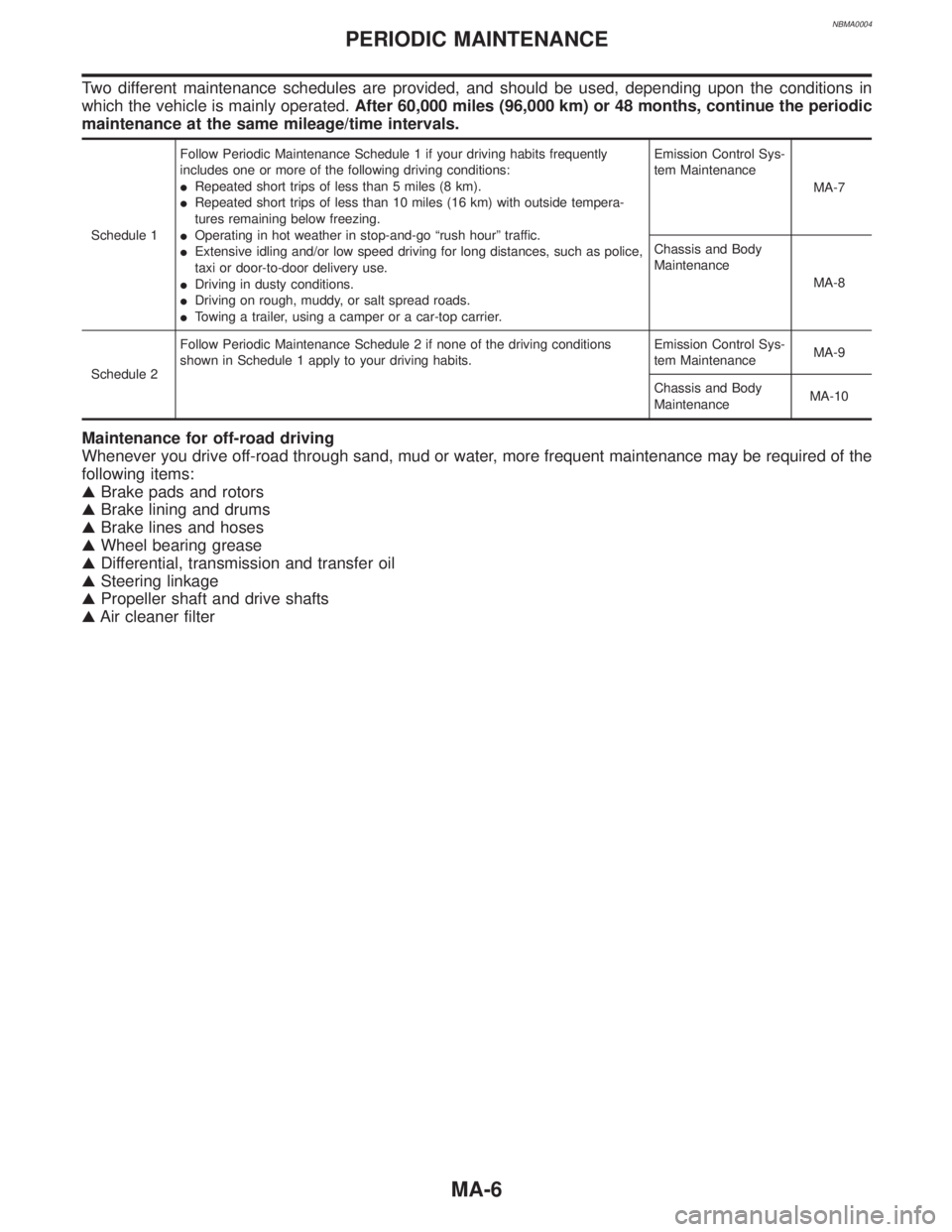
NBMA0004
Two different maintenance schedules are provided, and should be used, depending upon the conditions in
which the vehicle is mainly operated.After 60,000 miles (96,000 km) or 48 months, continue the periodic
maintenance at the same mileage/time intervals.
Schedule 1Follow Periodic Maintenance Schedule 1 if your driving habits frequently
includes one or more of the following driving conditions:
IRepeated short trips of less than 5 miles (8 km).
IRepeated short trips of less than 10 miles (16 km) with outside tempera-
tures remaining below freezing.
IOperating in hot weather in stop-and-go ªrush hourº traffic.
IExtensive idling and/or low speed driving for long distances, such as police,
taxi or door-to-door delivery use.
IDriving in dusty conditions.
IDriving on rough, muddy, or salt spread roads.
ITowing a trailer, using a camper or a car-top carrier.Emission Control Sys-
tem Maintenance
MA-7
Chassis and Body
Maintenance
MA-8
Schedule 2Follow Periodic Maintenance Schedule 2 if none of the driving conditions
shown in Schedule 1 apply to your driving habits.Emission Control Sys-
tem MaintenanceMA-9
Chassis and Body
MaintenanceMA-10
Maintenance for off-road driving
Whenever you drive off-road through sand, mud or water, more frequent maintenance may be required of the
following items:
GBrake pads and rotors
GBrake lining and drums
GBrake lines and hoses
GWheel bearing grease
GDifferential, transmission and transfer oil
GSteering linkage
GPropeller shaft and drive shafts
GAir cleaner filter
PERIODIC MAINTENANCE
MA-6
Page 2003 of 2395

CHASSIS AND BODY MAINTENANCENBMA0004S0102
Abbreviations: R = Replace. I = Inspect. Correct or replace if necessary. L = Lubricate
MAINTENANCE OPERATIONMAINTENANCE INTERVAL
Reference
Section
- Page or
- Content Title Perform at number of miles, kilo-
meters or months, whichever
comes first.Miles x 1,000
(km x 1,000)
Months3.75
(6)
37.5
(12)
611.25
(18)
915
(24)
1218.75
(30)
1522.5
(36)
1826.25
(42)
2130
(48)
2433.75
(54)
2737.5
(60)
3041.25
(66)
3345
(72)
3648.75
(78)
3952.5
(84)
4256.25
(90)
4560
(96)
48
Brake lines & cables I I I I MA-25
Brake pads, rotors, drums & linings I IIIIIIIMA-25, 26
Automatic transmission & all-mode
4WD transfer fluid & differential
gear oil (exc. LSD)NOTE (1) I I I I MA-21, 22, 23
LSD gear oil NOTE (1) I R I R MA-24
Steering gear, linkage & transfer
gear, axle & suspension partsIIIIIIIIMA-26
NOTE (6)
Tire rotation NOTE (2)MA-4
Drive shaft boots (
) IIIIIIIIAX-10, ªDrive
Shaftº
Propeller shaft NOTE (3) L LLLLLLLMA-23
Front wheel bearing grease (4x2) I I
Front wheel bearing
grease (
)NOTE (4) I R I RAX-4, ªFront
Wheel Bearingº
Exhaust system I IIIIIIIMA-21
Supplemental air bag systems NOTE (5)RS-14, ªMainte-
nance Itemsº
Ventilation air filter I RIRIRIRHA-159, ªVentila-
tion Air Filterº
ASCD vacuum hoses I I I IEL-237, ªASCD
ACTUATOR/
PUMP CHECKº
NOTE:
(1) If towing a trailer, using a camper or a car-top carrier, or driving on rough or muddy roads, change (not just inspect) fluid (A/T, all mode 4WD transfer)/differential gear oil (exc.
LSD) at every 30,000 miles (48,000 km) or 24 months, and change LSD gear oil every 15,000 miles (24,000 km) or 12 months.
(2) Refer to ªTire rotationº under the ªGENERAL MAINTENANCEº heading earlier in this section.
(3) The propeller shaft should be re-greased after being immersed in water.
(4) If operating frequently in water, replace grease every 3,750 miles (6,000 km) or 3 months.
(5) Inspect the air bag system 10 years after the date of manufacture noted on the FMVSS certification label.
(6) Refer to SU-5, ªFront Suspension Partsº and SU-16, ªRear Suspension Partsº, AX-3, ªFront Axle Partsº and AX-18, ªRear Axle Partsº.
PERIODIC MAINTENANCE
Schedule 1 (Cont'd)
MA-8