instrument cluster INFINITI QX4 2001 Factory Service Manual
[x] Cancel search | Manufacturer: INFINITI, Model Year: 2001, Model line: QX4, Model: INFINITI QX4 2001Pages: 2395, PDF Size: 43.2 MB
Page 479 of 2395

80845-71L00: 30 mm (1.18 in) thick, 30 x 50 mm (1.18 x 1.97 in)
FELT CLOTH TAPE
Used to insulate where movement does not occur. Ideal for instrument panel applications.
68370-4B000: 15 x 25 mm (0.59 x 0.98 in) pad/68239-13E00: 5 mm (0.20 in) wide tape roll
The following materials, not found in the kit, can also be used to repair squeaks and rattles.
UHMW (TEFLON) TAPE
Insulates where slight movement is present. Ideal for instrument panel applications.
SILICONE GREASE
Used in place of UHMW tape that will be visible or not fit.
Note: Will only last a few months.
SILICONE SPRAY
Use when grease cannot be applied.
DUCT TAPE
Use to eliminate movement.
CONFIRM THE REPAIRNBBT0024S06Confirm that the cause of a noise is repaired by test driving the vehicle. Operate the vehicle under the same
conditions as when the noise originally occurred. Refer to the notes on the Diagnostic Worksheet.
Generic Squeak and Rattle TroubleshootingNBBT0025Refer to Table of Contents for specific component removal and installation information.
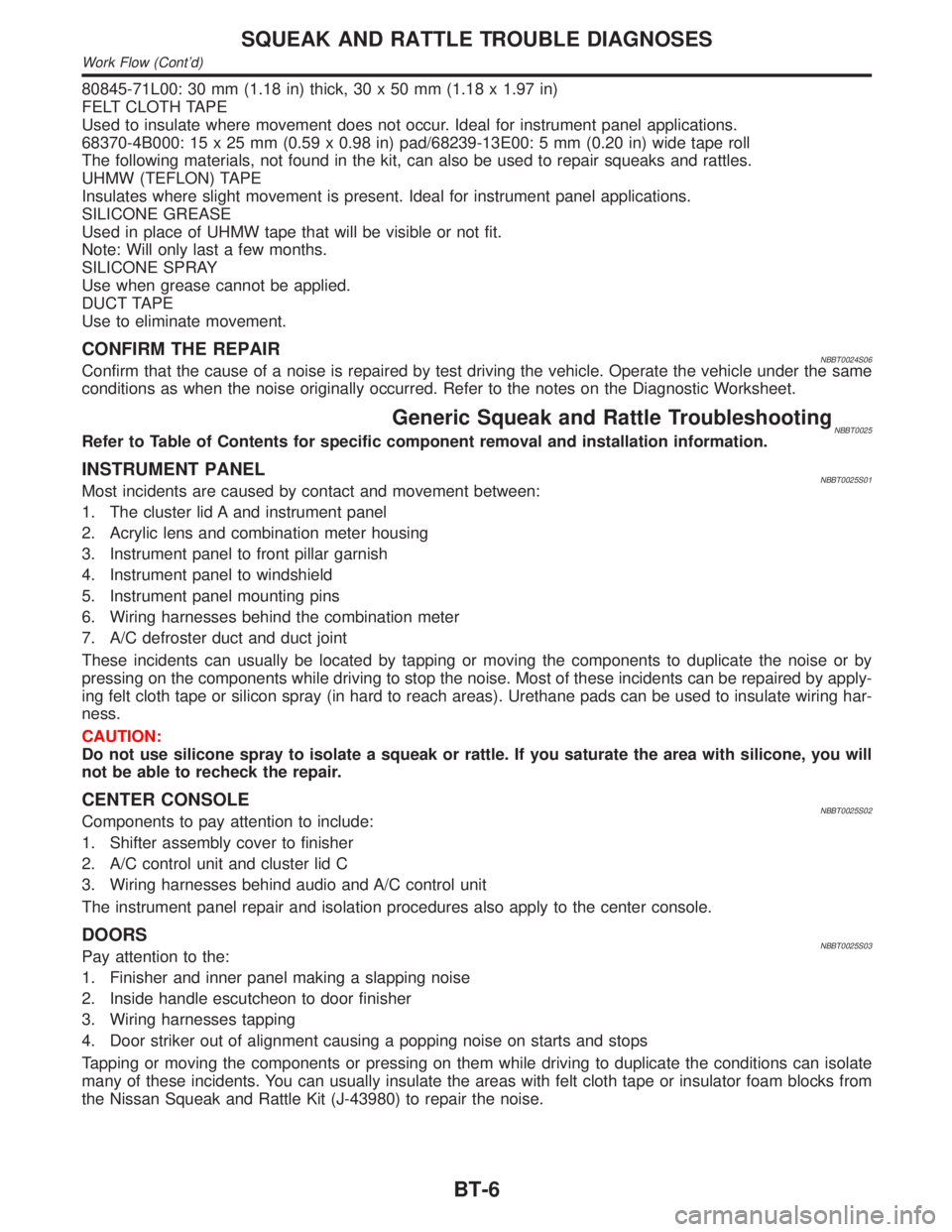
INSTRUMENT PANELNBBT0025S01Most incidents are caused by contact and movement between:
1. The cluster lid A and instrument panel
2. Acrylic lens and combination meter housing
3. Instrument panel to front pillar garnish
4. Instrument panel to windshield
5. Instrument panel mounting pins
6. Wiring harnesses behind the combination meter
7. A/C defroster duct and duct joint
These incidents can usually be located by tapping or moving the components to duplicate the noise or by
pressing on the components while driving to stop the noise. Most of these incidents can be repaired by apply-
ing felt cloth tape or silicon spray (in hard to reach areas). Urethane pads can be used to insulate wiring har-
ness.
CAUTION:
Do not use silicone spray to isolate a squeak or rattle. If you saturate the area with silicone, you will
not be able to recheck the repair.
CENTER CONSOLENBBT0025S02Components to pay attention to include:
1. Shifter assembly cover to finisher
2. A/C control unit and cluster lid C
3. Wiring harnesses behind audio and A/C control unit
The instrument panel repair and isolation procedures also apply to the center console.
DOORSNBBT0025S03Pay attention to the:
1. Finisher and inner panel making a slapping noise
2. Inside handle escutcheon to door finisher
3. Wiring harnesses tapping
4. Door striker out of alignment causing a popping noise on starts and stops
Tapping or moving the components or pressing on them while driving to duplicate the conditions can isolate
many of these incidents. You can usually insulate the areas with felt cloth tape or insulator foam blocks from
the Nissan Squeak and Rattle Kit (J-43980) to repair the noise.
SQUEAK AND RATTLE TROUBLE DIAGNOSES
Work Flow (Cont'd)
BT-6
Page 498 of 2395

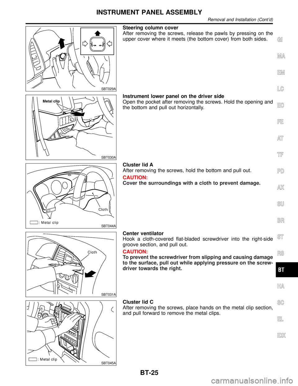
SBT029A
Steering column cover
After removing the screws, release the pawls by pressing on the
upper cover where it meets (the bottom cover) from both sides.
SBT030A
Instrument lower panel on the driver side
Open the pocket after removing the screws. Hold the opening and
the bottom and pull out horizontally.
SBT044A
Cluster lid A
After removing the screws, hold the bottom and pull out.
CAUTION:
Cover the surroundings with a cloth to prevent damage.
SBT031A
Center ventilator
Hook a cloth-covered flat-bladed screwdriver into the right-side
groove section, and pull out.
CAUTION:
To prevent the screwdriver from slipping and causing damage
to the surface, pull out while applying pressure on the screw-
driver towards the right.
SBT045A
Cluster lid C
After removing the screws, place hands on the metal clip section,
and pull forward to remove the metal clips.
GI
MA
EM
LC
EC
FE
AT
TF
PD
AX
SU
BR
ST
RS
HA
SC
EL
IDX
INSTRUMENT PANEL ASSEMBLY
Removal and Installation (Cont'd)
BT-25
Page 2289 of 2395

SMT862D
Transfer Control Unit Terminals and Reference
Value
NBTF0018REMOVAL AND INSTALLATION OF TRANSFER
CONTROL UNIT
NBTF0018S03RemovalNBTF0018S03011. Turn ignition switch OFF and disconnect negative battery ter-
minal.
2. Remove console box.
3. Remove cluster lid C.
4. Remove audio assembly and A/C control unit.
5. Remove instrument lower panel on driver side.
6. Remove glove box.
7. Remove instrument lower panel on passenger side.
8. Remove instrument lower center panel.
9. Remove transfer control unit.
IFor steps 2 through 8 above, refer to BT-21, ªInstrument Panel
Assemblyº.
InstallationNBTF0018S0302IInstallation is in the reverse order of removal.
When installing transfer control unit, tighten transfer control unit
lock nut.
Tightening torque:
: 4.3 - 5.8 N´m (0.44 - 0.59 kg-m, 38 - 51 in-lb)
SMT771D
INSPECTION OF TRANSFER CONTROL UNITNBTF0018S01IMeasure voltage between each terminal and terminal 6 or 45
by following ªTRANSFER CONTROL UNIT INSPECTION
TABLEº, TF-55.
IPin connector terminal layout
TROUBLE DIAGNOSIS Ð GENERAL DESCRIPTION
Transfer Control Unit Terminals and Reference Value
TF-54