fuel INFINITI QX4 2001 Factory Service Manual
[x] Cancel search | Manufacturer: INFINITI, Model Year: 2001, Model line: QX4, Model: INFINITI QX4 2001Pages: 2395, PDF Size: 43.2 MB
Page 11 of 2395
Precautions for Supplemental Restraint System
(SRS) ªAIR BAGº and ªSEAT BELT
PRE-TENSIONERº
NBAT0001The supplemental Restraint System such as ªAIR BAGº and ªSEAT BELT PRE-TENSIONERº used along with
a seat belt, helps to reduce the risk or severity of injury to the driver and front passenger for certain types of
collision. The SRS system composition which is available to INFINITI QX4 is as follows:
IFor a frontal collision
The Supplemental Restraint System consists of driver air bag module (located in the center of the steer-
ing wheel), front passenger air bag module (located on the instrument panel on passenger side), seat belt
pre-tensioners, a diagnosis sensor unit, warning lamp, wiring harness and spiral cable.
IFor a side collision
The Supplemental Restraint System consists of front side air bag module (located in the outer side of front
seat), satellite sensor, diagnosis sensor unit (one of components of air bags for a frontal collision), wiring
harness, warning lamp (one of components of air bags for a frontal collision).
Information necessary to service the system safely is included in theRS sectionof this Service Manual.
WARNING:
ITo avoid rendering the SRS inoperative, which could increase the risk of personal injury or death
in the event of a collision which would result in air bag inflation, all maintenance must be performed
by an authorized INFINITI dealer.
IImproper maintenance, including incorrect removal and installation of the SRS, can lead to per-
sonal injury caused by unintentional activation of the system. For removal of Spiral Cable and Air
Bag Module, see the RS section.
IDo not use electrical test equipment on any circuit related to the SRS unless instructed to in this
Service Manual. Spiral cable and wiring harnesses covered with yellow insulation tape either just
before the harness connectors or for the complete harness are related to the SRS.
Precautions for On Board Diagnostic (OBD)
System of A/T and Engine
NBAT0002The ECM has an on board diagnostic system. It will light up the malfunction indicator lamp (MIL) to warn the
driver of a malfunction causing emission deterioration.
CAUTION:
IBe sure to turn the ignition switch ªOFFº and disconnect the negative battery terminal before any
repair or inspection work. The open/short circuit of related switches, sensors, solenoid valves, etc.
will cause the MIL to light up.
IBe sure to connect and lock the connectors securely after work. A loose (unlocked) connector will
cause the MIL to light up due to an open circuit. (Be sure the connector is free from water, grease,
dirt, bent terminals, etc.)
IBe sure to route and secure the harnesses properly after work. Interference of the harness with a
bracket, etc. may cause the MIL to light up due to a short circuit.
IBe sure to connect rubber tubes properly after work. A misconnected or disconnected rubber tube
may cause the MIL to light up due to a malfunction of the EGR system or fuel injection system,
etc.
IBe sure to erase the unnecessary malfunction information (repairs completed) from the TCM and
ECM before returning the vehicle to the customer.
SEF289H
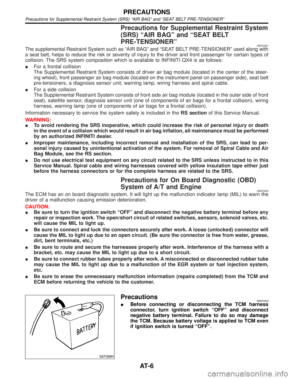
PrecautionsNBAT0003IBefore connecting or disconnecting the TCM harness
connector, turn ignition switch ªOFFº and disconnect
negative battery terminal. Failure to do so may damage
the TCM. Because battery voltage is applied to TCM even
if ignition switch is turned ªOFFº.
PRECAUTIONS
Precautions for Supplemental Restraint System (SRS) ªAIR BAGº and ªSEAT BELT PRE-TENSIONERº
AT-6
Page 33 of 2395
SAT007J
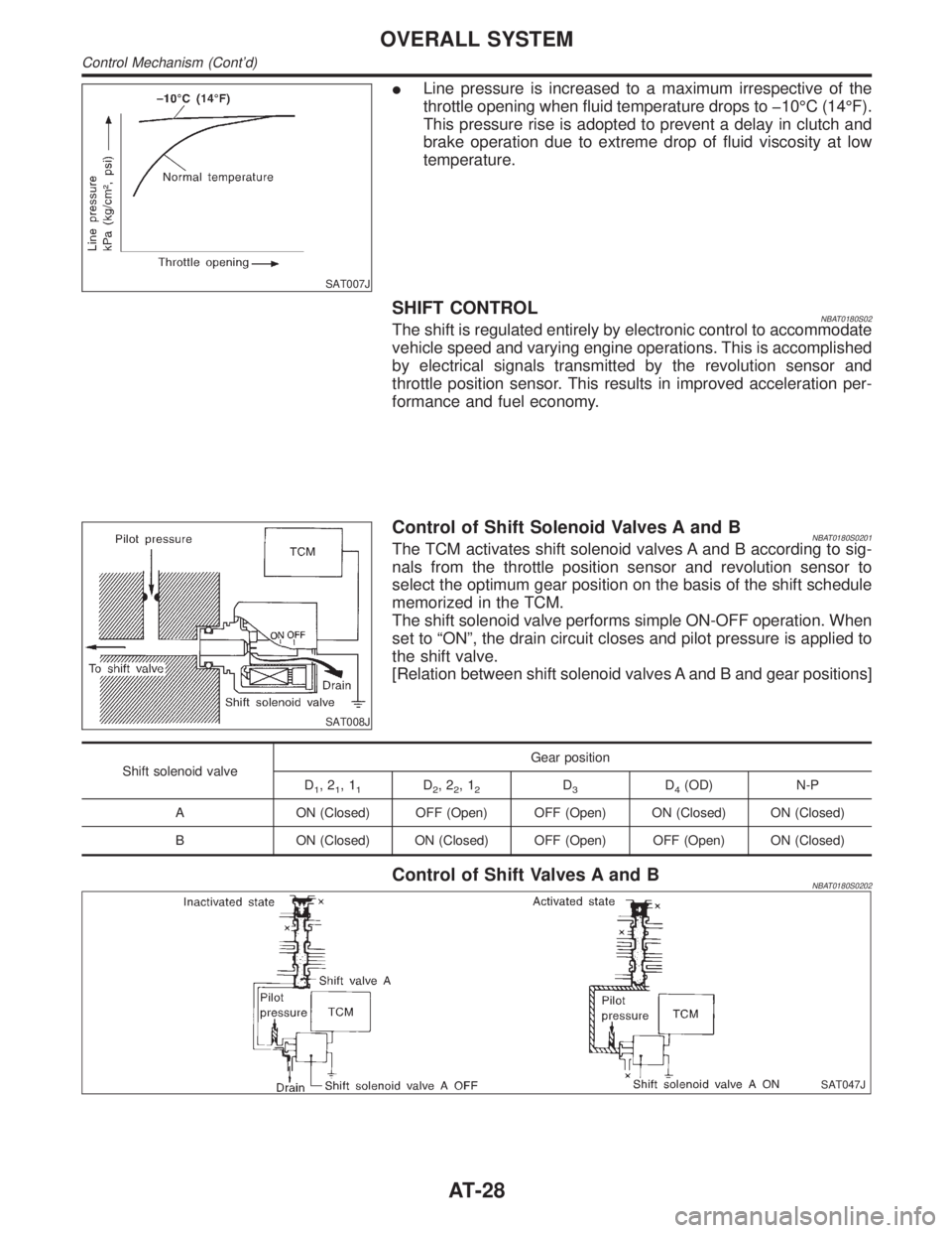
ILine pressure is increased to a maximum irrespective of the
throttle opening when fluid temperature drops to þ10ÉC (14ÉF).
This pressure rise is adopted to prevent a delay in clutch and
brake operation due to extreme drop of fluid viscosity at low
temperature.
SHIFT CONTROLNBAT0180S02The shift is regulated entirely by electronic control to accommodate
vehicle speed and varying engine operations. This is accomplished
by electrical signals transmitted by the revolution sensor and
throttle position sensor. This results in improved acceleration per-
formance and fuel economy.
SAT008J
Control of Shift Solenoid Valves A and BNBAT0180S0201The TCM activates shift solenoid valves A and B according to sig-
nals from the throttle position sensor and revolution sensor to
select the optimum gear position on the basis of the shift schedule
memorized in the TCM.
The shift solenoid valve performs simple ON-OFF operation. When
set to ªONº, the drain circuit closes and pilot pressure is applied to
the shift valve.
[Relation between shift solenoid valves A and B and gear positions]
Shift solenoid valveGear position
D
1,21,11D2,22,12D3D4(OD) N-P
A ON (Closed) OFF (Open) OFF (Open) ON (Closed) ON (Closed)
B ON (Closed) ON (Closed) OFF (Open) OFF (Open) ON (Closed)
Control of Shift Valves A and BNBAT0180S0202
SAT047J
OVERALL SYSTEM
Control Mechanism (Cont'd)
AT-28
Page 39 of 2395

SAT014K
If the DTC is being detected currently, the time data will be ª0º.
SAT015K
If a 1st trip DTC is stored in the ECM, the time data will be ª1tº.
SAT016K
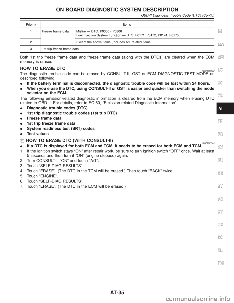
Freeze Frame Data and 1st Trip Freeze Frame DataNBAT0016S0101The ECM has a memory function, which stores the driving condition such as fuel system status, calculated
load value, engine coolant temperature, short term fuel trim, long term fuel trim, engine speed and vehicle
speed at the moment the ECM detects a malfunction.
Data which are stored in the ECM memory, along with the 1st trip DTC, are called 1st trip freeze frame data,
and the data, stored together with the DTC data, are called freeze frame data and displayed on CONSULT-II
or GST. The 1st trip freeze frame data can only be displayed on the CONSULT-II screen, not on the GST. For
detail, refer to EC-81, ªCONSULT-IIº.
Only one set of freeze frame data (either 1st trip freeze frame data of freeze frame data) can be stored in the
ECM. 1st trip freeze frame data is stored in the ECM memory along with the 1st trip DTC. There is no prior-
ity for 1st trip freeze frame data and it is updated each time a different 1st trip DTC is detected. However, once
freeze frame data (2nd trip detection/MIL on) is stored in the ECM memory, 1st trip freeze frame data is no
longer stored. Remember, only one set of freeze frame data can be stored in the ECM. The ECM has the fol-
lowing priorities to update the data.
ON BOARD DIAGNOSTIC SYSTEM DESCRIPTION
OBD-II Diagnostic Trouble Code (DTC) (Cont'd)
AT-34
Page 40 of 2395
Priority Items
1 Freeze frame data Misfire Ð DTC: P0300 - P0306
Fuel Injection System Function Ð DTC: P0171, P0172, P0174, P0175
2 Except the above items (Includes A/T related items)
3 1st trip freeze frame data
Both 1st trip freeze frame data and freeze frame data (along with the DTCs) are cleared when the ECM
memory is erased.
HOW TO ERASE DTCNBAT0016S02The diagnostic trouble code can be erased by CONSULT-II, GST or ECM DIAGNOSTIC TEST MODE as
described following.
IIf the battery terminal is disconnected, the diagnostic trouble code will be lost within 24 hours.
IWhen you erase the DTC, using CONSULT-II or GST is easier and quicker than switching the mode
selector on the ECM.
The following emission-related diagnostic information is cleared from the ECM memory when erasing DTC
related to OBD-II. For details, refer to EC-60, ªEmission-related Diagnostic Informationº.
IDiagnostic trouble codes (DTC)
I1st trip diagnostic trouble codes (1st trip DTC)
IFreeze frame data
I1st trip freeze frame data
ISystem readiness test (SRT) codes
ITest values
HOW TO ERASE DTC (WITH CONSULT-II)NBAT0016S03IIf a DTC is displayed for both ECM and TCM, it needs to be erased for both ECM and TCM.
1. If the ignition switch stays ªONº after repair work, be sure to turn ignition switch ªOFFº once. Wait at least
5 seconds and then turn it ªONº (engine stopped) again.
2. Turn CONSULT-II ªONº and touch ªA/Tº.
3. Touch ªSELF-DIAG RESULTSº.
4. Touch ªERASEº. (The DTC in the TCM will be erased.) Then touch ªBACKº twice.
5. Touch ªENGINEº.
6. Touch ªSELF-DIAG RESULTSº.
7. Touch ªERASEº. (The DTC in the ECM will be erased.)
GI
MA
EM
LC
EC
FE
TF
PD
AX
SU
BR
ST
RS
BT
HA
SC
EL
IDX
ON BOARD DIAGNOSTIC SYSTEM DESCRIPTION
OBD-II Diagnostic Trouble Code (DTC) (Cont'd)
AT-35
Page 369 of 2395
SBR686C
Precautions
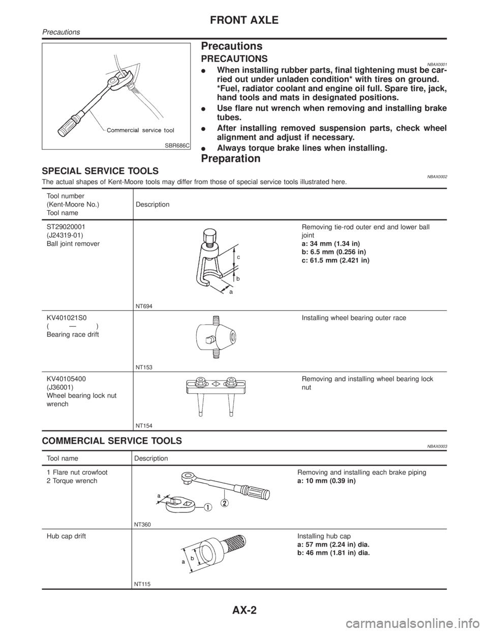
PRECAUTIONSNBAX0001IWhen installing rubber parts, final tightening must be car-
ried out under unladen condition* with tires on ground.
*Fuel, radiator coolant and engine oil full. Spare tire, jack,
hand tools and mats in designated positions.
IUse flare nut wrench when removing and installing brake
tubes.
IAfter installing removed suspension parts, check wheel
alignment and adjust if necessary.
IAlways torque brake lines when installing.
Preparation
SPECIAL SERVICE TOOLSNBAX0002The actual shapes of Kent-Moore tools may differ from those of special service tools illustrated here.
Tool number
(Kent-Moore No.)
Tool nameDescription
ST29020001
(J24319-01)
Ball joint remover
NT694
Removing tie-rod outer end and lower ball
joint
a: 34 mm (1.34 in)
b: 6.5 mm (0.256 in)
c: 61.5 mm (2.421 in)
KV401021S0
(Ð)
Bearing race drift
NT153
Installing wheel bearing outer race
KV40105400
(J36001)
Wheel bearing lock nut
wrench
NT154
Removing and installing wheel bearing lock
nut
COMMERCIAL SERVICE TOOLSNBAX0003
Tool name Description
1 Flare nut crowfoot
2 Torque wrench
NT360
Removing and installing each brake piping
a: 10 mm (0.39 in)
Hub cap drift
NT115
Installing hub cap
a: 57 mm (2.24 in) dia.
b: 46 mm (1.81 in) dia.
FRONT AXLE
Precautions
AX-2
Page 384 of 2395
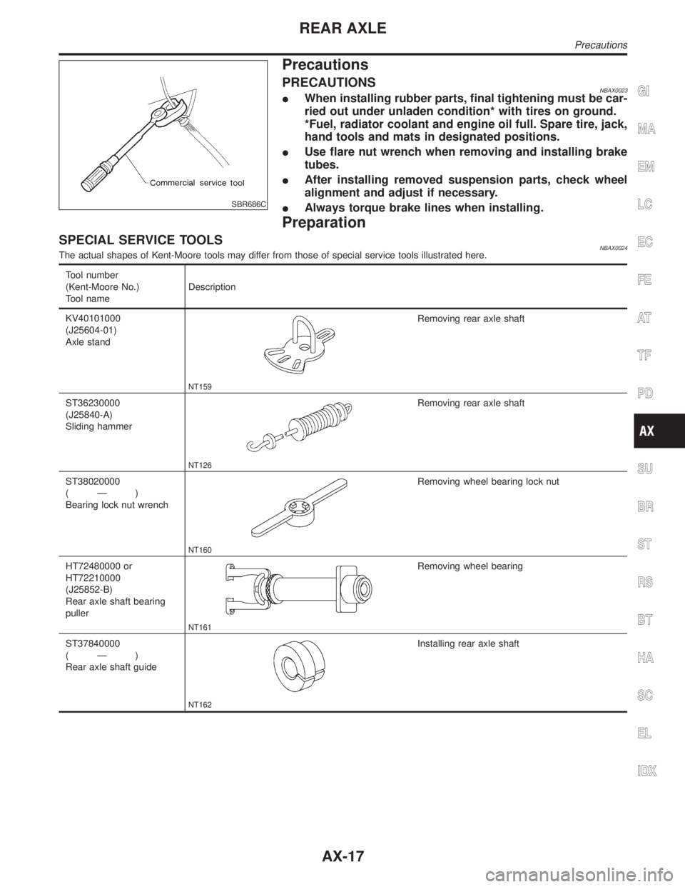
SBR686C
Precautions
PRECAUTIONSNBAX0023IWhen installing rubber parts, final tightening must be car-
ried out under unladen condition* with tires on ground.
*Fuel, radiator coolant and engine oil full. Spare tire, jack,
hand tools and mats in designated positions.
IUse flare nut wrench when removing and installing brake
tubes.
IAfter installing removed suspension parts, check wheel
alignment and adjust if necessary.
IAlways torque brake lines when installing.
Preparation
SPECIAL SERVICE TOOLSNBAX0024The actual shapes of Kent-Moore tools may differ from those of special service tools illustrated here.
Tool number
(Kent-Moore No.)
Tool nameDescription
KV40101000
(J25604-01)
Axle stand
NT159
Removing rear axle shaft
ST36230000
(J25840-A)
Sliding hammer
NT126
Removing rear axle shaft
ST38020000
(Ð)
Bearing lock nut wrench
NT160
Removing wheel bearing lock nut
HT72480000 or
HT72210000
(J25852-B)
Rear axle shaft bearing
puller
NT161
Removing wheel bearing
ST37840000
(Ð)
Rear axle shaft guide
NT162
Installing rear axle shaft
GI
MA
EM
LC
EC
FE
AT
TF
PD
SU
BR
ST
RS
BT
HA
SC
EL
IDX
REAR AXLE
Precautions
AX-17
Page 401 of 2395
InspectionNBBR0014CAUTION:
ICarefully monitor brake fluid level at master cylinder.
IUse new brake fluid ªDOT 3º.
IBe careful not to splash brake fluid on painted areas; it
may cause paint damage. If brake fluid is splashed on
paint areas, wash it away with water immediately.
IDepress pedal slowly when raising front brake pressure.
ICheck rear brake pressure 2 seconds after front brake
pressure reaches specified value.
IDisconnect harness connectors from ABS actuator and
electric unit before checking.
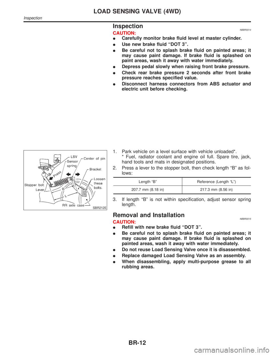
SBR212E
1. Park vehicle on a level surface with vehicle unloaded*.
* Fuel, radiator coolant and engine oil full. Spare tire, jack,
hand tools and mats in designated positions.
2. Press a lever to the stopper bolt, then check length ªBº as fol-
lows:
Length ªBº Reference (Length ªLº)
207.7 mm (8.18 in) 217.3 mm (8.56 in)
3. If length ªBº is not within specification, adjust sensor spring
length.
Removal and InstallationNBBR0015CAUTION:
IRefill with new brake fluid ªDOT 3º.
IBe careful not to splash brake fluid on painted areas; it
may cause paint damage. If brake fluid is splashed on
painted areas, wash it away with water immediately.
IDo not reuse Load Sensing Valve once it is disassembled.
IReplace damaged Load Sensing Valve as an assembly.
IWhen disassembling, apply multi-purpose grease to all
rubbing areas.
LOAD SENSING VALVE (4WD)
Inspection
BR-12
Page 503 of 2395

Removal and InstallationNBBT0010Front Door Trim
1. Remove inside handle escutcheon.
2. Remove power window switch, then disconnect the connectors.
3. Remove door armrest.
4. Remove bolts securing door finisher.
5. Pull on door finisher to remove clips from door panel and remove door finisher, then disconnect glass hatch
and fuel lid opener switch connector.
Rear Door Trim
6. Remove inside handle escutcheon.
7. Remove power window switch, then disconnect the connector.
8. Remove door armrest cap.
9. Remove bolts securing door finisher.
10. Pull on door finisher to remove clips from door panel and remove door finisher.
SBT696
DOOR TRIM
Removal and Installation
BT-30
Page 536 of 2395
ENGINE CONTROL SYSTEM
SECTION
EC
CONTENTS
TROUBLE DIAGNOSIS - INDEX....................................8
Alphabetical & P No. Index for DTC ...........................8
PRECAUTIONS.............................................................14
Supplemental Restraint System (SRS)²AIR
BAG²and²SEAT BELT PRE-TENSIONER².............14
Precautions for On Board Diagnostic (OBD)
System of Engine and A/T.........................................14
Engine Fuel & Emission Control System ..................15
Precautions ................................................................16
Wiring Diagrams and Trouble Diagnosis ...................17
PREPARATION.............................................................18
Special Service Tools ................................................18
Commercial Service Tools .........................................18
ENGINE AND EMISSION CONTROL OVERALL
SYSTEM.........................................................................20
Engine Control Component Parts Location ...............20
Circuit Diagram ..........................................................24
System Diagram ........................................................25
Vacuum Hose Drawing ..............................................26
System Chart .............................................................27
ENGINE AND EMISSION BASIC CONTROL
SYSTEM DESCRIPTION...............................................28
Multiport Fuel Injection (MFI) System .......................28
Electronic Ignition (EI) System ..................................30
Air Conditioning Cut Control ......................................31
Fuel Cut Control (at no load & high engine
speed) ........................................................................32
Evaporative Emission System ...................................32
Positive Crankcase Ventilation ..................................38
BASIC SERVICE PROCEDURE...................................39
Fuel Pressure Release ..............................................39
Fuel Pressure Check .................................................39
Fuel Pressure Regulator Check ................................40
Injector .......................................................................41
How to Check Idle Speed and Ignition Timing ..........42
Idle Speed/Ignition Timing/Idle Mixture Ratio
Adjustment .................................................................43
Idle Air Volume Learning ...........................................57ON BOARD DIAGNOSTIC SYSTEM
DESCRIPTION...............................................................59
Introduction ................................................................59
Two Trip Detection Logic ...........................................59
Emission-related Diagnostic Information ...................60
Malfunction Indicator Lamp (MIL) ..............................74
OBD System Operation Chart ...................................75
CONSULT-II ...............................................................81
Generic Scan Tool (GST) ..........................................95
TROUBLE DIAGNOSIS - INTRODUCTION..................97
Introduction ................................................................97
Work Flow ..................................................................99
TROUBLE DIAGNOSIS - BASIC INSPECTION.........101
Basic Inspection.......................................................101
TROUBLE DIAGNOSIS - GENERAL
DESCRIPTION............................................................. 116
DTC Inspection Priority Chart.................................. 116
Fail-safe Chart ......................................................... 117
Symptom Matrix Chart ............................................. 118
CONSULT-II Reference Value in Data Monitor
Mode ........................................................................122
Major Sensor Reference Graph in Data Monitor
Mode ........................................................................124
ECM Terminals and Reference Value .....................127
TROUBLE DIAGNOSIS - SPECIFICATION VALUE..136
Description ...............................................................136
Testing Condition .....................................................136
Inspection Procedure ...............................................136
Diagnostic Procedure ..............................................137
TROUBLE DIAGNOSIS FOR INTERMITTENT
INCIDENT.....................................................................140
Description ...............................................................140
Diagnostic Procedure ..............................................140
TROUBLE DIAGNOSIS FOR POWER SUPPLY........141
ECM Terminals and Reference Value .....................141
Main Power Supply and Ground Circuit ..................142
DTC P0100 MASS AIR FLOW SENSOR (MAFS)......150
Component Description ...........................................150
GI
MA
EM
LC
FE
AT
TF
PD
AX
SU
BR
ST
RS
BT
HA
SC
EL
IDX
Page 538 of 2395
CONSULT-II Reference Value in Data Monitor
Mode ........................................................................231
ECM Terminals and Reference Value .....................231
On Board Diagnosis Logic.......................................232
Possible Cause ........................................................232
DTC Confirmation Procedure ..................................232
Wiring Diagram ........................................................234
Diagnostic Procedure ..............................................236
DTC P0135, P0155 HEATED OXYGEN SENSOR 1
HEATER (FRONT) (BANK 1)/(BANK 2).....................240
Description ...............................................................240
CONSULT-II Reference Value in Data Monitor
Mode ........................................................................240
ECM Terminals and Reference Value .....................240
On Board Diagnosis Logic.......................................241
Possible Cause ........................................................241
DTC Confirmation Procedure ..................................241
Wiring Diagram ........................................................242
Diagnostic Procedure ..............................................244
DTC P0137, P0157 HEATED OXYGEN SENSOR 2
(REAR) (BANK 1)/(BANK 2) (MIN. VOLTAGE
MONITORING).............................................................247
Component Description ...........................................247
CONSULT-II Reference Value in Data Monitor
Mode ........................................................................247
ECM Terminals and Reference Value .....................247
On Board Diagnosis Logic.......................................247
Possible Cause ........................................................248
DTC Confirmation Procedure ..................................248
Overall Function Check ...........................................248
Wiring Diagram ........................................................250
Diagnostic Procedure ..............................................252
DTC P0138, P0158 HEATED OXYGEN SENSOR 2
(REAR) (BANK 1)/(BANK 2) (MAX. VOLTAGE
MONITORING).............................................................257
Component Description ...........................................257
CONSULT-II Reference Value in Data Monitor
Mode ........................................................................257
ECM Terminals and Reference Value .....................257
On Board Diagnosis Logic.......................................257
Possible Cause ........................................................258
DTC Confirmation Procedure ..................................258
Overall Function Check ...........................................258
Wiring Diagram ........................................................260
Diagnostic Procedure ..............................................262
DTC P0139, P0159 HEATED OXYGEN SENSOR 2
(REAR) (BANK 1)/(BANK 2) (RESPONSE
MONITORING).............................................................267
Component Description ...........................................267
CONSULT-II Reference Value in Data Monitor
Mode ........................................................................267
ECM Terminals and Reference Value .....................267On Board Diagnosis Logic.......................................267
Possible Cause ........................................................268
DTC Confirmation Procedure ..................................268
Overall Function Check ...........................................268
Wiring Diagram ........................................................270
Diagnostic Procedure ..............................................272
DTC P0140, P0160 HEATED OXYGEN SENSOR 2
(REAR) (BANK 1)/(BANK 2) (HIGH VOLTAGE)........277
Component Description ...........................................277
CONSULT-II Reference Value in Data Monitor
Mode ........................................................................277
ECM Terminals and Reference Value .....................277
On Board Diagnosis Logic.......................................277
Possible Cause ........................................................278
DTC Confirmation Procedure ..................................278
Overall Function Check ...........................................278
Wiring Diagram ........................................................280
Diagnostic Procedure ..............................................282
DTC P0141, P0161 HEATED OXYGEN SENSOR 2
HEATER (REAR) (BANK 1)/(BANK 2).......................286
Description ...............................................................286
CONSULT-II Reference Value in Data Monitor
Mode ........................................................................286
ECM Terminals and Reference Value .....................286
On Board Diagnosis Logic.......................................287
Possible Cause ........................................................287
DTC Confirmation Procedure ..................................287
Wiring Diagram ........................................................289
Diagnostic Procedure ..............................................291
DTC P0171 (RIGHT, -B1), P0174 (LEFT, -B2)
FUEL INJECTION SYSTEM FUNCTION (LEAN).......294
On Board Diagnosis Logic.......................................294
Possible Cause ........................................................294
DTC Confirmation Procedure ..................................294
Wiring Diagram ........................................................296
Diagnostic Procedure ..............................................298
DTC P0172 (RIGHT, -B1), P0175 (LEFT, -B2)
FUEL INJECTION SYSTEM FUNCTION (RICH)........302
On Board Diagnosis Logic.......................................302
Possible Cause ........................................................302
DTC Confirmation Procedure ..................................302
Wiring Diagram ........................................................304
Diagnostic Procedure ..............................................306
DTC P0180 FUEL TANK TEMPERATURE
SENSOR......................................................................309
Component Description ...........................................309
On Board Diagnosis Logic.......................................309
Possible Cause ........................................................309
DTC Confirmation Procedure ..................................310
Wiring Diagram ........................................................ 311
Diagnostic Procedure ..............................................312GI
MA
EM
LC
FE
AT
TF
PD
AX
SU
BR
ST
RS
BT
HA
SC
EL
IDX
CONTENTS(Cont'd)
EC-3