maintenance INFINITI QX4 2001 Factory Service Manual
[x] Cancel search | Manufacturer: INFINITI, Model Year: 2001, Model line: QX4, Model: INFINITI QX4 2001Pages: 2395, PDF Size: 43.2 MB
Page 2 of 2395
FOREWORD
This manual contains maintenance and repair procedures for the
2001 INFINITI QX4.
In order to assure your safety and the efficient functioning of the
vehicle, this manual should be read thoroughly. It is especially
important that the PRECAUTIONS in the GI section be completely
understood before starting any repair task.
All information in this manual is based on the latest product infor-
mation at the time of publication. The right is reserved to make
changes in specifications and methods at any time without notice.
IMPORTANT SAFETY NOTICE
The proper performance of service is essential for both the safety of
the technician and the efficient functioning of the vehicle.
The service methods in this Service Manual are described in such a
manner that the service may be performed safely and accurately.
Service varies with the procedures used, the skills of the technician
and the tools and parts available. Accordingly, anyone using service
procedures, tools or parts which are not specifically recommended
by INFINITI must first be completely satisfied that neither personal
safety nor the vehicle's safety will be jeopardized by the service
method selected.
Page 11 of 2395
Precautions for Supplemental Restraint System
(SRS) ªAIR BAGº and ªSEAT BELT
PRE-TENSIONERº
NBAT0001The supplemental Restraint System such as ªAIR BAGº and ªSEAT BELT PRE-TENSIONERº used along with
a seat belt, helps to reduce the risk or severity of injury to the driver and front passenger for certain types of
collision. The SRS system composition which is available to INFINITI QX4 is as follows:
IFor a frontal collision
The Supplemental Restraint System consists of driver air bag module (located in the center of the steer-
ing wheel), front passenger air bag module (located on the instrument panel on passenger side), seat belt
pre-tensioners, a diagnosis sensor unit, warning lamp, wiring harness and spiral cable.
IFor a side collision
The Supplemental Restraint System consists of front side air bag module (located in the outer side of front
seat), satellite sensor, diagnosis sensor unit (one of components of air bags for a frontal collision), wiring
harness, warning lamp (one of components of air bags for a frontal collision).
Information necessary to service the system safely is included in theRS sectionof this Service Manual.
WARNING:
ITo avoid rendering the SRS inoperative, which could increase the risk of personal injury or death
in the event of a collision which would result in air bag inflation, all maintenance must be performed
by an authorized INFINITI dealer.
IImproper maintenance, including incorrect removal and installation of the SRS, can lead to per-
sonal injury caused by unintentional activation of the system. For removal of Spiral Cable and Air
Bag Module, see the RS section.
IDo not use electrical test equipment on any circuit related to the SRS unless instructed to in this
Service Manual. Spiral cable and wiring harnesses covered with yellow insulation tape either just
before the harness connectors or for the complete harness are related to the SRS.
Precautions for On Board Diagnostic (OBD)
System of A/T and Engine
NBAT0002The ECM has an on board diagnostic system. It will light up the malfunction indicator lamp (MIL) to warn the
driver of a malfunction causing emission deterioration.
CAUTION:
IBe sure to turn the ignition switch ªOFFº and disconnect the negative battery terminal before any
repair or inspection work. The open/short circuit of related switches, sensors, solenoid valves, etc.
will cause the MIL to light up.
IBe sure to connect and lock the connectors securely after work. A loose (unlocked) connector will
cause the MIL to light up due to an open circuit. (Be sure the connector is free from water, grease,
dirt, bent terminals, etc.)
IBe sure to route and secure the harnesses properly after work. Interference of the harness with a
bracket, etc. may cause the MIL to light up due to a short circuit.
IBe sure to connect rubber tubes properly after work. A misconnected or disconnected rubber tube
may cause the MIL to light up due to a malfunction of the EGR system or fuel injection system,
etc.
IBe sure to erase the unnecessary malfunction information (repairs completed) from the TCM and
ECM before returning the vehicle to the customer.
SEF289H
PrecautionsNBAT0003IBefore connecting or disconnecting the TCM harness
connector, turn ignition switch ªOFFº and disconnect
negative battery terminal. Failure to do so may damage
the TCM. Because battery voltage is applied to TCM even
if ignition switch is turned ªOFFº.
PRECAUTIONS
Precautions for Supplemental Restraint System (SRS) ªAIR BAGº and ªSEAT BELT PRE-TENSIONERº
AT-6
Page 386 of 2395
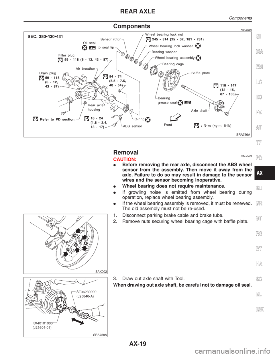
ComponentsNBAX0028
SRA756A
RemovalNBAX0029CAUTION:
IBefore removing the rear axle, disconnect the ABS wheel
sensor from the assembly. Then move it away from the
axle. Failure to do so may result in damage to the sensor
wires and the sensor becoming inoperative.
IWheel bearing does not require maintenance.
IIf growling noise is emitted from wheel bearing during
operation, replace wheel bearing assembly.
IIf the wheel bearing assembly is removed, it must be renewed.
The old assembly must not be re-used.
SAX002
1. Disconnect parking brake cable and brake tube.
2. Remove nuts securing wheel bearing cage with baffle plate.
SRA758A
3. Draw out axle shaft with Tool.
When drawing out axle shaft, be careful not to damage oil seal.
GI
MA
EM
LC
EC
FE
AT
TF
PD
SU
BR
ST
RS
BT
HA
SC
EL
IDX
REAR AXLE
Components
AX-19
Page 392 of 2395
Supplemental Restraint System (SRS) ªAIR
BAGº and ªSEAT BELT PRE-TENSIONERº
NBBR0001The Supplemental Restraint System such as ªAIR BAGº and ªSEAT BELT PRE-TENSIONERº used along with
a seat belt, helps to reduce the risk or severity of injury to the driver and front passenger for certain types of
collision. The SRS system composition which is available to INFINITI QX4 is as follows:
IFor a frontal collision
The Supplemental Restraint System consists of driver air bag module (located in the center of the steer-
ing wheel), front passenger air bag module (located on the instrument panel on passenger side), seat belt
pre-tensioners, a diagnosis sensor unit, warning lamp, wiring harness and spiral cable.
IFor a side collision
The Supplemental Restraint System consists of side air bag module (located in the outer side of front seat),
satellite sensor, diagnosis sensor unit (one of components of air bags for a frontal collision), wiring harness,
warning lamp (one of components of air bags for a frontal collision).
Information necessary to service the system safely is included in theRS sectionof this Service Manual.
WARNING:
ITo avoid rendering the SRS inoperative, which could increase the risk of personal injury or death
in the event of a collision which would result in air bag inflation, all maintenance must be performed
by an authorized INFINITI dealer.
IImproper maintenance, including incorrect removal and installation of the SRS, can lead to per-
sonal injury caused by unintentional activation of the system. For removal of Spiral Cable and Air
Bag Module, see the RS section.
IDo not use electrical test equipment on any circuit related to the SRS unless instructed to in this
Service Manual. Spiral cable and wiring harnesses covered with yellow insulation tape either just
before the harness connectors or for the complete harness are related to the SRS.
SBR686C
Precautions for Brake SystemNBBR0002IUse brake fluid ªDOT 3º.
INever reuse drained brake fluid.
IBe careful not to splash brake fluid on painted areas; it
may cause paint damage. If brake fluid is splashed on
painted areas, wash it away with water immediately.
ITo clean master cylinder parts, disc brake caliper parts or
wheel cylinder parts, use clean brake fluid.
INever use mineral oils such as gasoline or kerosene. They
will ruin rubber parts of hydraulic system.
IUse flare nut wrench when removing and installing brake
tubes.
IAlways torque brake lines when installing.
WARNING:
IClean brakes with a vacuum dust collector to minimize
risk of health hazard from powder caused by friction.
GI
MA
EM
LC
EC
FE
AT
TF
PD
AX
SU
ST
RS
BT
HA
SC
EL
IDX
PRECAUTIONS
Supplemental Restraint System (SRS) ªAIR BAGº and ªSEAT BELT PRE-TENSIONERº
BR-3
Page 475 of 2395

Service NoticeNBBT0001IWhen removing or installing various parts, place a cloth or padding onto the vehicle body to prevent
scratches.
IHandle trim, molding, instruments, grille, etc. carefully during removing or installing. Be careful not to soil
or damage them.
IApply sealing compound where necessary when installing parts.
IWhen applying sealing compound, be careful that the sealing compound does not protrude from parts.
IWhen replacing any metal parts (for example body outer panel, members, etc.), be sure to take rust pre-
vention measures.
Supplemental Restraint System (SRS) ªAIR
BAGº and ªSEAT BELT PRE-TENSIONERº
NBBT0002The Supplemental Restraint System such as ªAIR BAGº and ªSEAT BELT PRE-TENSIONERº used along with
a seat belt, helps to reduce the risk or severity of injury to the driver and front passenger for certain types of
collision. The SRS system composition which is available to INFINITI QX4 is as follows:
IFor a frontal collision
The Supplemental Restraint System consists of driver air bag module (located in the center of the steer-
ing wheel), front passenger air bag module (located on the instrument panel on passenger side), seat belt
pre-tensioners, a diagnosis sensor unit, warning lamp, wiring harness and spiral cable.
IFor a side collision
The Supplemental Restraint System consists of side air bag module (located in the outer side of front seat),
satellite sensor, diagnosis sensor unit (one of components of air bags for a frontal collision), wiring harness,
warning lamp (one of components of air bags for a frontal collision).
Information necessary to service the system safely is included in theRS sectionof this Service Manual.
WARNING:
ITo avoid rendering the SRS inoperative, which could increase the risk of personal injury or death
in the event of a collision which would result in air bag inflation, all maintenance must be performed
by an authorized INFINITI dealer.
IImproper maintenance, including incorrect removal and installation of the SRS, can lead to per-
sonal injury caused by unintentional activation of the system. For removal of Spiral Cable and Air
Bag Module, see the RS section.
IDo not use electrical test equipment on any circuit related to the SRS unless instructed to in this
Service Manual. Spiral cable and wiring harnesses covered with yellow insulation tape either just
before the harness connectors or for the complete harness are related to the SRS.
PRECAUTIONS
Service Notice
BT-2
Page 549 of 2395
Supplemental Restraint System (SRS) ªAIR
BAGº and ªSEAT BELT PRE-TENSIONERº
NBEC0002The Supplemental Restraint System such as ªAIR BAGº and ªSEAT BELT PRE-TENSIONERº used along with
a seat belt, helps to reduce the risk or severity of injury to the driver and front passenger for certain types of
collision. The SRS system composition which is available to INFINITI QX4 is as follows:
IFor a frontal collision
The Supplemental Restraint System consists of driver air bag module (located in the center of the steer-
ing wheel), front passenger air bag module (located on the instrument panel on passenger side), seat belt
pre-tensioners, a diagnosis sensor unit, warning lamp, wiring harness and spiral cable.
IFor a side collision
The Supplemental Restraint System consists of front side air bag module (located in the outer side of front
seat), satellite sensor, diagnosis sensor unit (one of components of air bags for a frontal collision), wiring
harness, warning lamp (one of components of air bags for a frontal collision).
Information necessary to service the system safely is included in theRS sectionof this Service Manual.
WARNING:
ITo avoid rendering the SRS inoperative, which could increase the risk of personal injury or death
in the event of a collision which would result in air bag inflation, all maintenance must be performed
by an authorized INFINITI dealer.
IImproper maintenance, including incorrect removal and installation of the SRS, can lead to per-
sonal injury caused by unintentional activation of the system. For removal of Spiral Cable and Air
Bag Module, see the RS section.
IDo not use electrical test equipment on any circuit related to the SRS unless instructed to in this
Service Manual. Spiral cable and wiring harnesses covered with yellow insulation tape either just
before the harness connectors or for the complete harness are related to the SRS.
Precautions for On Board Diagnostic (OBD)
System of Engine and A/T
NBEC0003The ECM has an on board diagnostic system. It will light up the malfunction indicator lamp (MIL) to warn the
driver of a malfunction causing emission deterioration.
CAUTION:
IBe sure to turn the ignition switch OFF and disconnect the negative battery terminal before any
repair or inspection work. The open/short circuit of related switches, sensors, solenoid valves, etc.
will cause the MIL to light up.
IBe sure to connect and lock the connectors securely after work. A loose (unlocked) connector will
cause the MIL to light up due to the open circuit. (Be sure the connector is free from water, grease,
dirt, bent terminals, etc.)
ICertain systems and components, especially those related to OBD, may use a new style slide-
locking type harness connector. For description and how to disconnect, refer to EL-6, ªHARNESS
CONNECTOR (SLIDE-LOCKING TYPE)º.
IBe sure to route and secure the harnesses properly after work. The interference of the harness with
a bracket, etc. may cause the MIL to light up due to the short circuit.
IBe sure to connect rubber tubes properly after work. A misconnected or disconnected rubber tube
may cause the MIL to light up due to the malfunction of the fuel injection system, etc.
IBe sure to erase the unnecessary malfunction information (repairs completed) from the ECM and
TCM (Transmission control module) before returning the vehicle to the customer.
PRECAUTIONS
Supplemental Restraint System (SRS) ªAIR BAGº and ªSEAT BELT PRE-TENSIONERº
EC-14
Page 595 of 2395
Emission-related Diagnostic InformationNBEC0031DTC AND 1ST TRIP DTCNBEC0031S01The 1st trip DTC (whose number is the same as the DTC number) is displayed for the latest self-diagnostic
result obtained. If the ECM memory was cleared previously, and the 1st trip DTC did not reoccur, the 1st trip
DTC will not be displayed.
If a malfunction is detected during the 1st trip, the 1st trip DTC is stored in the ECM memory. The MIL will not
light up (two trip detection logic). If the same malfunction is not detected in the 2nd trip (meeting the required
driving pattern), the 1st trip DTC is cleared from the ECM memory. If the same malfunction is detected in the
2nd trip, both the 1st trip DTC and DTC are stored in the ECM memory and the MIL lights up. In other words,
the DTC is stored in the ECM memory and the MIL lights up when the same malfunction occurs in two con-
secutive trips. If a 1st trip DTC is stored and a non-diagnostic operation is performed between the 1st and
2nd trips, only the 1st trip DTC will continue to be stored. For malfunctions that blink or light up the MIL dur-
ing the 1st trip, the DTC and 1st trip DTC are stored in the ECM memory.
Procedures for clearing the DTC and the 1st trip DTC from the ECM memory are described in ªHOW TO
ERASE EMISSION-RELATED DIAGNOSTIC INFORMATIONº, EC-72.
For malfunctions in which 1st trip DTCs are displayed, refer to EC-69. These items are required by legal
regulations to continuously monitor the system/component. In addition, the items monitored non-continuously
are also displayed on CONSULT-II.
1st trip DTC is specified in Mode 7 of SAE J1979. 1st trip DTC detection occurs without lighting up the MIL
and therefore does not warn the driver of a problem. However, 1st trip DTC detection will not prevent the
vehicle from being tested, for example during Inspection/Maintenance (I/M) tests.
When a 1st trip DTC is detected, check, print out or write down and erase (1st trip) DTC and Freeze Frame
data as specified in ªWork Flowº procedure Step II, refer to EC-99. Then perform ªDTC Confirmation Proce-
dureº or ªOverall Function Checkº to try to duplicate the problem. If the malfunction is duplicated, the item
requires repair.
How to Read DTC and 1st Trip DTCNBEC0031S0101DTC and 1st trip DTC can be read by the following methods.
With CONSULT-II
With GST
CONSULT-II or GST (Generic Scan Tool) Examples: P0340, P1320, P0705, P0750, etc.
These DTCs are prescribed by SAE J2012.
(CONSULT-II also displays the malfunctioning component or system.)
I1st trip DTC No. is the same as DTC No.
IOutput of a DTC indicates a malfunction. However, GST does not indicate whether the malfunction
is still occurring or has occurred in the past and has returned to normal. CONSULT-II can identify
malfunction status as shown below. Therefore, using CONSULT-II (if available) is recommended.
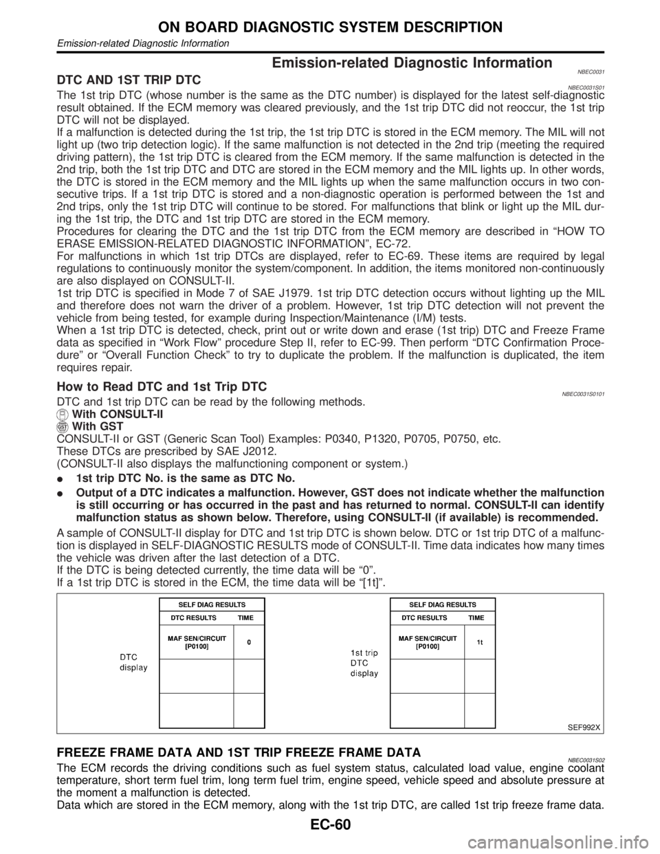
A sample of CONSULT-II display for DTC and 1st trip DTC is shown below. DTC or 1st trip DTC of a malfunc-
tion is displayed in SELF-DIAGNOSTIC RESULTS mode of CONSULT-II. Time data indicates how many times
the vehicle was driven after the last detection of a DTC.
If the DTC is being detected currently, the time data will be ª0º.
If a 1st trip DTC is stored in the ECM, the time data will be ª[1t]º.
SEF992X
FREEZE FRAME DATA AND 1ST TRIP FREEZE FRAME DATANBEC0031S02The ECM records the driving conditions such as fuel system status, calculated load value, engine coolant
temperature, short term fuel trim, long term fuel trim, engine speed, vehicle speed and absolute pressure at
the moment a malfunction is detected.
Data which are stored in the ECM memory, along with the 1st trip DTC, are called 1st trip freeze frame data.
ON BOARD DIAGNOSTIC SYSTEM DESCRIPTION
Emission-related Diagnostic Information
EC-60
Page 596 of 2395
The data, stored together with the DTC data, are called freeze frame data and displayed on CONSULT-II or
GST. The 1st trip freeze frame data can only be displayed on the CONSULT-II screen, not on the GST. For
details, see EC-85.
Only one set of freeze frame data (either 1st trip freeze frame data or freeze frame data) can be stored in the
ECM. 1st trip freeze frame data is stored in the ECM memory along with the 1st trip DTC. There is no prior-
ity for 1st trip freeze frame data and it is updated each time a different 1st trip DTC is detected. However, once
freeze frame data (2nd trip detection/MIL on) is stored in the ECM memory, 1st trip freeze frame data is no
longer stored. Remember, only one set of freeze frame data can be stored in the ECM. The ECM has the fol-
lowing priorities to update the data.
Priority Items
1Freeze frame data Misfire Ð DTC: P0300 - P0306
Fuel Injection System Function Ð DTC: P0171, P0172, P0174, P0175
2 Except the above items (Includes A/T related items)
3 1st trip freeze frame data
For example, the EGR malfunction (Priority: 2) was detected and the freeze frame data was stored in the 2nd
trip. After that when the misfire (Priority: 1) is detected in another trip, the freeze frame data will be updated
from the EGR malfunction to the misfire. The 1st trip freeze frame data is updated each time a different mal-
function is detected. There is no priority for 1st trip freeze frame data. However, once freeze frame data is
stored in the ECM memory, 1st trip freeze data is no longer stored (because only one freeze frame data or
1st trip freeze frame data can be stored in the ECM). If freeze frame data is stored in the ECM memory and
freeze frame data with the same priority occurs later, the first (original) freeze frame data remains unchanged
in the ECM memory.
Both 1st trip freeze frame data and freeze frame data (along with the DTCs) are cleared when the ECM
memory is erased. Procedures for clearing the ECM memory are described in ªHOW TO ERASE EMISSION-
RELATED DIAGNOSTIC INFORMATIONº, EC-72.
SYSTEM READINESS TEST (SRT) CODENBEC0031S03System Readiness Test (SRT) code is specified in Mode 1 of SAE J1979.
As part of an enhanced emissions test for Inspection & Maintenance (I/M), certain states require the status of
SRT be used to indicate whether the ECM has completed self-diagnosis of major emission systems and com-
ponents. Completion must be verified in order for the emissions inspection to proceed.
If a vehicle is rejected for a State emissions inspection due to one or more SRT items indicating ªINCMPº,
use the information in this Service Manual to set the SRT to ªCMPLTº.
In most cases the ECM will automatically complete its self-diagnosis cycle during normal usage, and the SRT
status will indicate ªCMPLTº for each application system. Once set as ªCMPLTº, the SRT status remains
ªCMPLTº until the self-diagnosis memory is erased.
Occasionally, certain portions of the self-diagnostic test may not be completed as a result of the customer's
normal driving pattern; the SRT will indicate ªINCMPº for these items.
NOTE:
The SRT will also indicate ªINCMPº if the self-diagnosis memory is erased for any reason or if the ECM
memory power supply is interrupted for several hours.
If, during the state emissions inspection, the SRT indicates ªCMPLTº for all test items, the inspector will con-
tinue with the emissions test. However, if the SRT indicates ªINCMPº for one or more of the SRT items the
vehicle is returned to the customer untested.
NOTE:
If MIL is ªONº during the state emissions inspection, the vehicle is also returned to the customer untested even
though the SRT indicates ªCMPLTº for all test items. Therefore, it is important to check SRT (ªCMPLTº) and
DTC (No DTCs) before the inspection.
GI
MA
EM
LC
FE
AT
TF
PD
AX
SU
BR
ST
RS
BT
HA
SC
EL
IDX
ON BOARD DIAGNOSTIC SYSTEM DESCRIPTION
Emission-related Diagnostic Information (Cont'd)
EC-61
Page 636 of 2395

Basic InspectionNBEC0038Precaution:
Perform Basic Inspection without electrical or mechanical
loads applied;
IHeadlamp switch is OFF,
IAir conditioner switch is OFF,
IRear window defogger switch is OFF,
ISteering wheel is in the straight-ahead position, etc.
1 INSPECTION START
1. Check service records for any recent repairs that may indicate a related problem, or a current need for scheduled
maintenance.
2. Open engine hood and check the following:
IHarness connectors for improper connections
IVacuum hoses for splits, kinks and improper connections
IWiring for improper connections, pinches and cuts
IAir cleaner clogging
IHoses and ducts for leaks
SEF983U
©GO TO 2.
2 CHECK THROTTLE OPENER OPERATION-I
Confirm that there is a clearance between throttle drum and stopper.
SEF950Y
OK or NG
OK©GO TO 4.
NG©GO TO 3.
GI
MA
EM
LC
FE
AT
TF
PD
AX
SU
BR
ST
RS
BT
HA
SC
EL
IDX
TROUBLE DIAGNOSIS Ð BASIC INSPECTION
Basic Inspection
EC-101
Page 854 of 2395
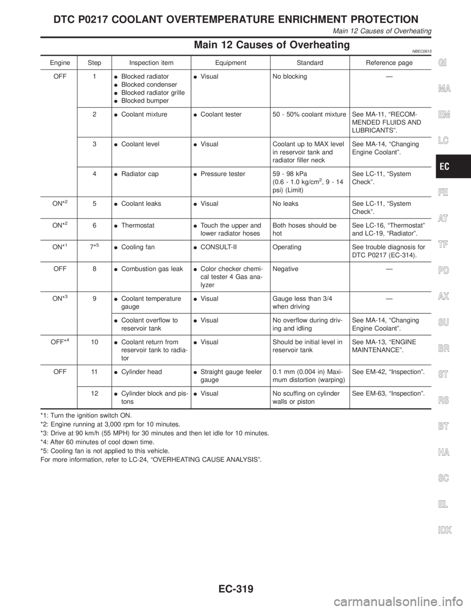
Main 12 Causes of OverheatingNBEC0615
Engine Step Inspection item Equipment Standard Reference page
OFF 1IBlocked radiator
IBlocked condenser
IBlocked radiator grille
IBlocked bumperIVisual No blocking Ð
2ICoolant mixtureICoolant tester 50 - 50% coolant mixture See MA-11, ªRECOM-
MENDED FLUIDS AND
LUBRICANTSº.
3ICoolant levelIVisual Coolant up to MAX level
in reservoir tank and
radiator filler neckSee MA-14, ªChanging
Engine Coolantº.
4IRadiator capIPressure tester 59 - 98 kPa
(0.6 - 1.0 kg/cm
2,9-14
psi) (Limit)See LC-11, ªSystem
Checkº.
ON*
25ICoolant leaksIVisual No leaks See LC-11, ªSystem
Checkº.
ON*
26IThermostatITouch the upper and
lower radiator hosesBoth hoses should be
hotSee LC-16, ªThermostatº
and LC-19, ªRadiatorº.
ON*
17*5ICooling fanICONSULT-II Operating See trouble diagnosis for
DTC P0217 (EC-314).
OFF 8ICombustion gas leakIColor checker chemi-
cal tester 4 Gas ana-
lyzerNegative Ð
ON*
39ICoolant temperature
gaugeIVisual Gauge less than 3/4
when drivingÐ
ICoolant overflow to
reservoir tankIVisual No overflow during driv-
ing and idlingSee MA-14, ªChanging
Engine Coolantº.
OFF*
410ICoolant return from
reservoir tank to radia-
torIVisual Should be initial level in
reservoir tankSee MA-13, ªENGINE
MAINTENANCEº.
OFF 11ICylinder headIStraight gauge feeler
gauge0.1 mm (0.004 in) Maxi-
mum distortion (warping)See EM-42, ªInspectionº.
12ICylinder block and pis-
tonsIVisual No scuffing on cylinder
walls or pistonSee EM-63, ªInspectionº.
*1: Turn the ignition switch ON.
*2: Engine running at 3,000 rpm for 10 minutes.
*3: Drive at 90 km/h (55 MPH) for 30 minutes and then let idle for 10 minutes.
*4: After 60 minutes of cool down time.
*5: Cooling fan is not applied to this vehicle.
For more information, refer to LC-24, ªOVERHEATING CAUSE ANALYSISº.
GI
MA
EM
LC
FE
AT
TF
PD
AX
SU
BR
ST
RS
BT
HA
SC
EL
IDX
DTC P0217 COOLANT OVERTEMPERATURE ENRICHMENT PROTECTION
Main 12 Causes of Overheating
EC-319