recommended oil INFINITI QX4 2001 Factory Service Manual
[x] Cancel search | Manufacturer: INFINITI, Model Year: 2001, Model line: QX4, Model: INFINITI QX4 2001Pages: 2395, PDF Size: 43.2 MB
Page 13 of 2395
IBefore assembly, apply a coat of recommended ATF to all
parts. Apply petroleum jelly to protect O-rings and seals, or
hold bearings and washers in place during assembly. Do not
use grease.
IExtreme care should be taken to avoid damage to O-rings,
seals and gaskets when assembling.
IReplace ATF cooler if excessive foreign material is found in oil
pan or clogging strainer. Refer to ªATF COOLER SERVICEº,
AT-9.
IAfter overhaul, refill the transmission with new ATF.
IWhen the A/T drain plug is removed, only some of the fluid is
drained. Old A/T fluid will remain in torque converter and ATF
cooling system.
Always follow the procedures when changing A/T fluid. Refer
to MA-21, ªChanging A/T Fluidº.
Service Notice or PrecautionsNBAT0004FAIL-SAFENBAT0004S01The TCM has an electronic Fail-Safe (limp home mode). This allows the vehicle to be driven even if a major
electrical input/output device circuit is damaged.
Under Fail-Safe, the vehicle always runs in third gear, even with a shift lever position of ª1º, ª2º or ªDº. The
customer may complain of sluggish or poor acceleration.
When the ignition key is turned ªONº following Fail-Safe operation, O/D OFF indicator lamp blinks for about
8 seconds. (For ªTCM SELF-DIAGNOSTIC PROCEDURE (No Tools)º, refer to AT-46.)
Fail-Safe may occur without electrical circuit damage if the vehicle is driven under extreme conditions (such
as excessive wheel spin followed by sudden braking). To recover normal shift pattern, turn the ignition key
ªOFFº for 5 seconds, then ªONº.
The blinking of the O/D OFF indicator lamp for about 8 seconds will appear only once and be cleared. The
customer may resume normal driving conditions.
Always follow the ªWORK FLOWº (Refer to AT-57).
The SELF-DIAGNOSIS results will be as follows:
The first SELF-DIAGNOSIS will indicate damage to the vehicle speed sensor or the revolution sensor.
During the next SELF-DIAGNOSIS, performed after checking the sensor, no damages will be indicated.
TORQUE CONVERTER SERVICENBAT0004S04The torque converter should be replaced under any of the following conditions:
IExternal leaks in the hub weld area.
IConverter hub is scored or damaged.
IConverter pilot is broken, damaged or fits poorly into crankshaft.
ISteel particles are found after flushing the cooler and cooler lines.
IPump is damaged or steel particles are found in the converter.
IVehicle has TCC shudder and/or no TCC apply. Replace only after all hydraulic and electrical diagnoses
have been made. (Converter clutch material may be glazed.)
IConverter is contaminated with engine coolant containing antifreeze.
IInternal failure of stator roller clutch.
IHeavy clutch debris due to overheating (blue converter).
ISteel particles or clutch lining material found in fluid filter or on magnet when no internal parts in unit are
worn or damaged Ð indicates that lining material came from converter.
The torque converter should not be replaced if:
IThe fluid has an odor, is discolored, and there is no evidence of metal or clutch facing particles.
PRECAUTIONS
Precautions (Cont'd)
AT-8
Page 356 of 2395

SAT993A
f. Install oil pump assembly.
IInstall two converter housing securing bolts in bolt holes
in oil pump assembly as guides.
SAT994A
IInsert oil pump assembly to the specified position in
transmission, as shown at left.
SAT114B
5. Install O-ring on input shaft.
IApply ATF to O-rings.
SAT397C
6. Install converter housing.
a. Apply recommended sealant (Genuine anaerobic liquid
gasket, Three Bond TB1215, Locktite Part No. 51813 or
equivalent) to outer periphery of bolt holes in converter hous-
ing.
IDo not apply too much sealant.
SAT158G
b. Apply recommended sealant (Genuine anaerobic liquid
gasket, Three Bond TB1215, Locktite Part No. 51813 or
equivalent) to seating surfaces of bolts that secure front of
converter housing.
c. Install converter housing on transmission case.
GI
MA
EM
LC
EC
FE
TF
PD
AX
SU
BR
ST
RS
BT
HA
SC
EL
IDX
ASSEMBLY
Assembly (2) (Cont'd)
AT-351
Page 566 of 2395
System DescriptionNBEC0015S02
SEF742M
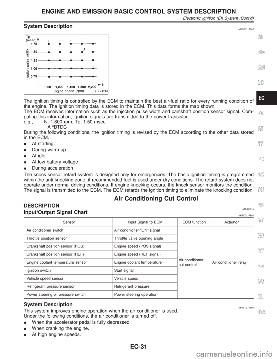
The ignition timing is controlled by the ECM to maintain the best air-fuel ratio for every running condition of
the engine. The ignition timing data is stored in the ECM. This data forms the map shown.
The ECM receives information such as the injection pulse width and camshaft position sensor signal. Com-
puting this information, ignition signals are transmitted to the power transistor.
e.g., N: 1,800 rpm, Tp: 1.50 msec
A ÉBTDC
During the following conditions, the ignition timing is revised by the ECM according to the other data stored
in the ECM.
IAt starting
IDuring warm-up
IAt idle
IAt low battery voltage
IDuring acceleration
The knock sensor retard system is designed only for emergencies. The basic ignition timing is programmed
within the anti-knocking zone, if recommended fuel is used under dry conditions. The retard system does not
operate under normal driving conditions. If engine knocking occurs, the knock sensor monitors the condition.
The signal is transmitted to the ECM. The ECM retards the ignition timing to eliminate the knocking condition.
Air Conditioning Cut Control
DESCRIPTIONNBEC0016Input/Output Signal ChartNBEC0016S01
Sensor Input Signal to ECM ECM function Actuator
Air conditioner switch Air conditioner ªONº signal
Air conditioner
cut controlAir conditioner relay Throttle position sensor Throttle valve opening angle
Crankshaft position sensor (POS) Engine speed (POS signal)
Crankshaft position sensor (REF) Engine speed (REF signal)
Engine coolant temperature sensor Engine coolant temperature
Ignition switch Start signal
Vehicle speed sensor Vehicle speed
Refrigerant pressure sensor Refrigerant pressure
Power steering oil pressure switch Power steering operation
System DescriptionNBEC0016S02This system improves engine operation when the air conditioner is used.
Under the following conditions, the air conditioner is turned off.
IWhen the accelerator pedal is fully depressed.
IWhen cranking the engine.
IAt high engine speeds.
GI
MA
EM
LC
FE
AT
TF
PD
AX
SU
BR
ST
RS
BT
HA
SC
EL
IDX
ENGINE AND EMISSION BASIC CONTROL SYSTEM DESCRIPTION
Electronic Ignition (EI) System (Cont'd)
EC-31
Page 1751 of 2395
IClean all disassembled parts in the designated liquid or solvent
prior to inspection or assembly.
IReplace oil seals, gaskets, packings, O-rings, locking washers,
cotter pins, self-locking nuts, etc. with new ones.
IReplace inner and outer races of tapered roller bearings and
needle bearings as a set.
IArrange the disassembled parts in accordance with their
assembled locations and sequence.
IDo not touch the terminals of electrical components which use
microcomputers (such as ECMs).
Static electricity may damage internal electronic components.
IAfter disconnecting vacuum or air hoses, attach a tag to indi-
cate the proper connection.
IUse only the fluids and lubricants specified in this manual.
IUse approved bonding agent, sealants or their equivalents
when required.
IUse tools and recommended special tools where specified for
safe and efficient service repairs.
IWhen repairing the fuel, oil, water, vacuum or exhaust
systems, check all affected lines for leaks.
IDispose of drained oil or the solvent used for cleaning parts in
an appropriate manner.
WARNING:
To prevent ECM from storing the diagnostic trouble codes, do
not carelessly disconnect the harness connectors which are
related to the engine control system and TCM (Transmission
Control Module) system. The connectors should be discon-
nected only when working according to the WORK FLOW of
TROUBLE DIAGNOSES in EC and AT sections.
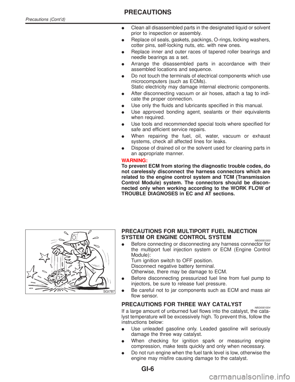
SGI787
PRECAUTIONS FOR MULTIPORT FUEL INJECTION
SYSTEM OR ENGINE CONTROL SYSTEM
NBGI0001S03IBefore connecting or disconnecting any harness connector for
the multiport fuel injection system or ECM (Engine Control
Module):
Turn ignition switch to OFF position.
Disconnect negative battery terminal.
Otherwise, there may be damage to ECM.
IBefore disconnecting pressurized fuel line from fuel pump to
injectors, be sure to release fuel pressure.
IBe careful not to jar components such as ECM and mass air
flow sensor.
PRECAUTIONS FOR THREE WAY CATALYSTNBGI0001S04If a large amount of unburned fuel flows into the catalyst, the cata-
lyst temperature will be excessively high. To prevent this, follow the
instructions below:
IUse unleaded gasoline only. Leaded gasoline will seriously
damage the three way catalyst.
IWhen checking for ignition spark or measuring engine
compression, make tests quickly and only when necessary.
IDo not run engine when the fuel tank level is low, otherwise the
engine may misfire causing damage to the catalyst.
PRECAUTIONS
Precautions (Cont'd)
GI-6
Page 1753 of 2395
PRECAUTIONS FOR ENGINE OILSNBGI0001S05Prolonged and repeated contact with used engine oil may cause
skin cancer. Try to avoid direct skin contact with used oil.
If skin contact is made, wash thoroughly with soap or hand cleaner
as soon as possible.
Health Protection PrecautionsNBGI0001S0501IAvoid prolonged and repeated contact with oils, particularly
used engine oils.
IWear protective clothing, including impervious gloves where
practicable.
IDo not put oily rags in pockets.
IAvoid contaminating clothes, particularly underpants, with oil.
IHeavily soiled clothing and oil-impregnated footwear should
not be worn. Overalls must be cleaned regularly.
IFirst Aid treatment should be obtained immediately for open
cuts and wounds.
IUse barrier creams, applying them before each work period, to
help the removal of oil from the skin.
IWash with soap and water to ensure all oil is removed (skin
cleansers and nail brushes will help). Preparations containing
lanolin replace the natural skin oils which have been removed.
IDo not use gasoline, kerosine, diesel fuel, gas oil, thinners or
solvents for cleaning skin.
IIf skin disorders develop, obtain medical advice without delay.
IWhere practicable, degrease components prior to handling.
IWhere there is a risk of eye contact, eye protection should be
worn, for example, chemical goggles or face shields; in addi-
tion an eye wash facility should be provided.
Environmental Protection PrecautionsNBGI0001S0502Burning used engine oil in small space heaters or boilers can be
recommended only for units of approved design. The heating sys-
tem must meet the requirements of HM Inspectorate of Pollution for
small burners of less than 0.4 MW. If in doubt check with the
appropriate local authority and/or manufacturer of the approved
appliance.
Dispose of used oil and used oil filters through authorized waste
disposal contractors to licensed waste disposal sites, or to the
waste oil reclamation trade. If in doubt, contact the local authority
for advice on disposal facilities.
It is illegal to pour used oil on to the ground, down sewers or drains,
or into water courses.
The regulations concerning pollution vary between regions.
PRECAUTIONS FOR FUELNBGI0001S06Use unleaded gasoline with an octane rating of at least 87 AKI
(Anti-Knock Index) number (research octane number 91).
CAUTION:
Do not use leaded gasoline. Using leaded gasoline will dam-
age the three way catalyst.
Using a fuel other than that specified could adversely affect
the emission control devices and systems, and could also
affect the warranty coverage validity.
PRECAUTIONS FOR AIR CONDITIONINGNBGI0001S07Use an approved refrigerant recovery unit any time the air condi-
tioning system must be discharged. Refer to HA-144, ªHFC-134a
(R-134a) Service Procedureº for specific instructions.
PRECAUTIONS
Precautions (Cont'd)
GI-8
Page 1755 of 2395
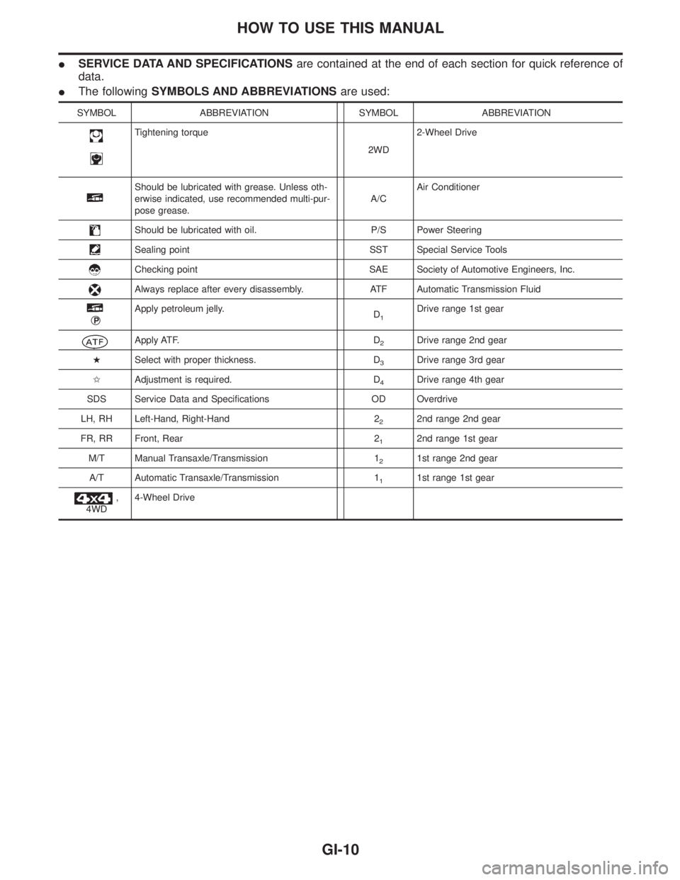
ISERVICE DATA AND SPECIFICATIONSare contained at the end of each section for quick reference of
data.
IThe followingSYMBOLS AND ABBREVIATIONSare used:
SYMBOL ABBREVIATION SYMBOL ABBREVIATION
Tightening torque
2WD2-Wheel Drive
Should be lubricated with grease. Unless oth-
erwise indicated, use recommended multi-pur-
pose grease.A/CAir Conditioner
Should be lubricated with oil. P/S Power Steering
Sealing point SST Special Service Tools
Checking point SAE Society of Automotive Engineers, Inc.
Always replace after every disassembly. ATF Automatic Transmission Fluid
qP
Apply petroleum jelly.
D1Drive range 1st gear
Apply ATF. D2Drive range 2nd gear
HSelect with proper thickness. D
3Drive range 3rd gear
IAdjustment is required. D
4Drive range 4th gear
SDS Service Data and Specifications OD Overdrive
LH, RH Left-Hand, Right-Hand 2
22nd range 2nd gear
FR, RR Front, Rear 2
12nd range 1st gear
M/T Manual Transaxle/Transmission 1
21st range 2nd gear
A/T Automatic Transaxle/Transmission 1
11st range 1st gear
,
4WD4-Wheel Drive
HOW TO USE THIS MANUAL
GI-10
Page 1806 of 2395
Precautions for Service EquipmentNBHA0006RECOVERY/RECYCLING EQUIPMENTNBHA0006S01Be certain to follow the manufacturers instructions for machine
operation and machine maintenance. Never introduce any refriger-
ant other than that specified into the machine.
ELECTRONIC LEAK DETECTORNBHA0006S02Be certain to follow the manufacturer's instructions for tester opera-
tion and tester maintenance.
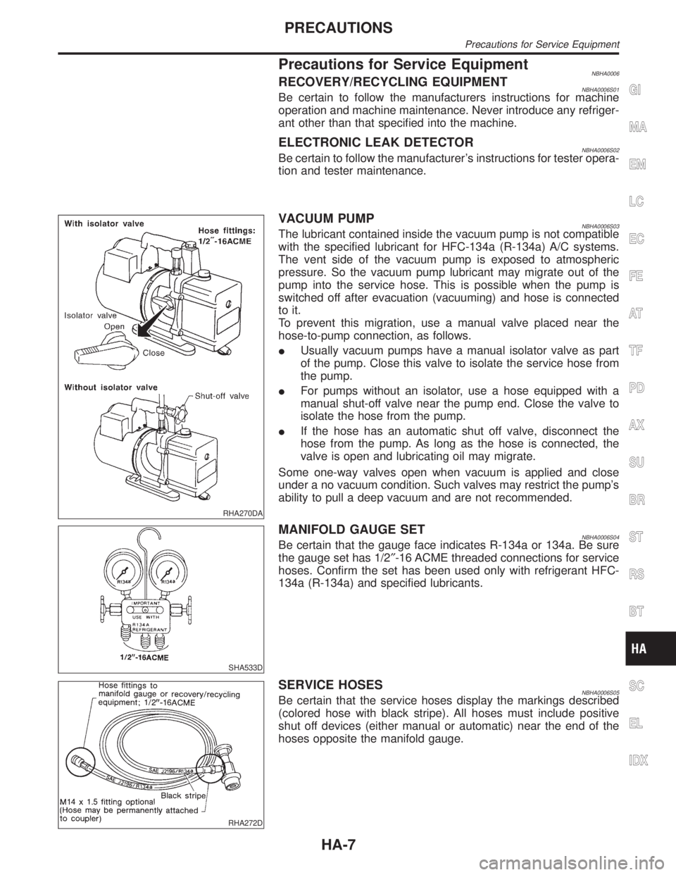
RHA270DA
VACUUM PUMPNBHA0006S03The lubricant contained inside the vacuum pump is not compatible
with the specified lubricant for HFC-134a (R-134a) A/C systems.
The vent side of the vacuum pump is exposed to atmospheric
pressure. So the vacuum pump lubricant may migrate out of the
pump into the service hose. This is possible when the pump is
switched off after evacuation (vacuuming) and hose is connected
to it.
To prevent this migration, use a manual valve placed near the
hose-to-pump connection, as follows.
IUsually vacuum pumps have a manual isolator valve as part
of the pump. Close this valve to isolate the service hose from
the pump.
IFor pumps without an isolator, use a hose equipped with a
manual shut-off valve near the pump end. Close the valve to
isolate the hose from the pump.
IIf the hose has an automatic shut off valve, disconnect the
hose from the pump. As long as the hose is connected, the
valve is open and lubricating oil may migrate.
Some one-way valves open when vacuum is applied and close
under a no vacuum condition. Such valves may restrict the pump's
ability to pull a deep vacuum and are not recommended.
SHA533D
MANIFOLD GAUGE SETNBHA0006S04Be certain that the gauge face indicates R-134a or 134a. Be sure
the gauge set has 1/2²-16 ACME threaded connections for service
hoses. Confirm the set has been used only with refrigerant HFC-
134a (R-134a) and specified lubricants.
RHA272D
SERVICE HOSESNBHA0006S05Be certain that the service hoses display the markings described
(colored hose with black stripe). All hoses must include positive
shut off devices (either manual or automatic) near the end of the
hoses opposite the manifold gauge.
GI
MA
EM
LC
EC
FE
AT
TF
PD
AX
SU
BR
ST
RS
BT
SC
EL
IDX
PRECAUTIONS
Precautions for Service Equipment
HA-7
Page 1996 of 2395
MAINTENANCE
SECTION
MA
CONTENTS
PRECAUTIONS...............................................................2
Supplemental Restraint System (SRS)²AIR
BAG²and²SEAT BELT PRE-TENSIONER²...............2
PREPARATION...............................................................3
Special Service Tool ....................................................3
Commercial Service Tool .............................................3
GENERAL MAINTENANCE............................................4
PERIODIC MAINTENANCE............................................6
Schedule 1 ...................................................................7
EMISSION CONTROL SYSTEM MAINTENANCE.........7
CHASSIS AND BODY MAINTENANCE........................8
Schedule 2 ...................................................................9
EMISSION CONTROL SYSTEM MAINTENANCE.........9
CHASSIS AND BODY MAINTENANCE......................10
RECOMMENDED FLUIDS AND LUBRICANTS........... 11
Fluids and Lubricants ................................................ 11
SAE Viscosity Number ..............................................12
GASOLINE ENGINE OIL..........................................12
GEAR OIL...............................................................12
Anti-freeze Coolant Mixture Ratio .............................12
ENGINE MAINTENANCE..............................................13
Checking Drive Belts .................................................13
Changing Engine Coolant..........................................14
-DRAINING ENGINE COOLANT-..............................14
-REFILLING ENGINE COOLANT-..............................15
-FLUSHING COOLING SYSTEM-..............................16
Checking Fuel Lines ..................................................16
Changing Fuel Filter ..................................................16
WITH CONSULT-II..............................................16
WITHOUT CONSULT-II.......................................17
Changing Air Cleaner Filter .......................................17
VISCOUS PAPER TYPE...........................................17
Changing Engine Oil..................................................18
Changing Oil Filter .....................................................18
Changing Spark Plugs ...............................................19
Checking EVAP Vapor Lines .....................................20
CHASSIS AND BODY MAINTENANCE.......................21
Checking Exhaust System.........................................21
Checking A/T Fluid ....................................................21
Changing A/T Fluid ....................................................21Checking All-mode 4WD Transfer Fluid ....................22
Changing All-mode 4WD Transfer Fluid ....................22
Checking Propeller Shaft ...........................................23
Greasing Propeller Shaft ...........................................23
Checking Differential Gear Oil ...................................23
Changing Differential Gear Oil ..................................24
LIMITED-SLIP DIFFERENTIAL GEAR........................24
Balancing Wheels ......................................................24
Tire Rotation ..............................................................24
Checking Brake Fluid Level and Leaks.....................25
Checking Brake Lines and Cables ............................25
Checking Disc Brake .................................................25
ROTOR...................................................................25
CALIPER.................................................................25
PAD........................................................................25
Checking Drum Brake ...............................................26
WHEEL CYLINDER..................................................26
DRUM.....................................................................26
LINING....................................................................26
TEMPORARY METHOD FOR CHECKING LINING
WEAR
.....................................................................26
Checking Steering Gear, Linkage and Transfer
Gear ...........................................................................26
STEERING GEAR....................................................26
STEERING LINKAGE...............................................26
STEERING TRANSFER GEAR..................................26
Checking Power Steering Fluid and Lines ................27
CHECKING FLUID LEVEL........................................27
CHECKING LINES...................................................27
Lubricating Locks, Hinges and Hood Latches...........27
Checking Seat Belts, Buckles, Retractors,
Anchors and Adjusters...............................................28
SERVICE DATA AND SPECIFICATIONS (SDS).........29
Engine Maintenance ..................................................29
DRIVE BELT DEFLECTION......................................29
DRIVE BELT TENSION............................................29
SPARK PLUG TYPE................................................29
Chassis and Body Maintenance ................................29
WHEEL BALANCE...................................................29
GI
EM
LC
EC
FE
AT
TF
PD
AX
SU
BR
ST
RS
BT
HA
SC
EL
IDX
Page 2002 of 2395
![INFINITI QX4 2001 Factory Service Manual Schedule 1NBMA0004S01EMISSION CONTROL SYSTEM MAINTENANCENBMA0004S0101
Abbreviations: R = Replace. I = Inspect. Correct or replace if necessary. [ ]: At the mileage intervals only
MAINTENANCE OPERATION INFINITI QX4 2001 Factory Service Manual Schedule 1NBMA0004S01EMISSION CONTROL SYSTEM MAINTENANCENBMA0004S0101
Abbreviations: R = Replace. I = Inspect. Correct or replace if necessary. [ ]: At the mileage intervals only
MAINTENANCE OPERATION](/img/42/57027/w960_57027-2001.png)
Schedule 1NBMA0004S01EMISSION CONTROL SYSTEM MAINTENANCENBMA0004S0101
Abbreviations: R = Replace. I = Inspect. Correct or replace if necessary. [ ]: At the mileage intervals only
MAINTENANCE OPERATIONMAINTENANCE INTERVAL
Reference
Section
- Page or
- Content Title Perform at number of miles, kilo-
meters or months, whichever
comes first.Miles x 1,000
(km x 1,000)
Months3.75
(6)
37.5
(12)
611.25
(18)
915
(24)
1218.75
(30)
1522.5
(36)
1826.25
(42)
2130
(48)
2433.75
(54)
2737.5
(60)
3041.25
(66)
3345
(72)
3648.75
(78)
3952.5
(84)
4256.25
(90)
4560
(96)
48
Drive beltsI* I* MA-13
Air cleaner filter NOTE (1) [R] [R] MA-17
EVAP vapor linesI* I* MA-20
Fuel linesI* I* MA-16
Fuel filter* NOTE (2)MA-16
Engine coolant NOTE (3)R* MA-14
Engine oil RRRRRRRRRRRRRRRRMA-18
Engine oil filter (Use part No.
15208-31U00 or equivalent.)RRRRRRRRRRRRRRRRMA-18
Spark plugs (PLATINUM-TIPPED
type)Replace every 105,000 miles (169,000 km) MA-19
Intake & exhaust valve clearance* NOTE (4)EM-52, ªValve
Clearanceº
NOTE:
(1) If operating mainly in dusty conditions, more frequent maintenance may be required.
(2) When the filter becomes clogged, the vehicle speed cannot be increased as the driver wishes. In such an event, replace the filter.
(3) After 60,000 miles (96,000 km) or 48 months, replace every 30,000 miles (48,000 km) or 24 months.
(4) If valve noise increases, inspect valve clearance.
HMaintenance items and intervals with ª*º are recommended by INFINITI for reliable vehicle operation. The owner need not perform such maintenance in order to maintain the
emission warranty or manufacturer recall liability. Other maintenance items and intervals are required.
GI
EM
LC
EC
FE
AT
TF
PD
AX
SU
BR
ST
RS
BT
HA
SC
EL
IDX
PERIODIC MAINTENANCE
Schedule 1
MA-7
Page 2004 of 2395
![INFINITI QX4 2001 Factory Service Manual Schedule 2NBMA0004S02EMISSION CONTROL SYSTEM MAINTENANCENBMA0004S0201
Abbreviations: R = Replace. I = Inspect. Correct or replace if necessary. [ ]: At the mileage intervals only
MAINTENANCE OPERATION INFINITI QX4 2001 Factory Service Manual Schedule 2NBMA0004S02EMISSION CONTROL SYSTEM MAINTENANCENBMA0004S0201
Abbreviations: R = Replace. I = Inspect. Correct or replace if necessary. [ ]: At the mileage intervals only
MAINTENANCE OPERATION](/img/42/57027/w960_57027-2003.png)
Schedule 2NBMA0004S02EMISSION CONTROL SYSTEM MAINTENANCENBMA0004S0201
Abbreviations: R = Replace. I = Inspect. Correct or replace if necessary. [ ]: At the mileage intervals only
MAINTENANCE OPERATIONMAINTENANCE INTERVAL
Reference Section
- Page
or
- Content Title Perform at number of miles, kilometers
or months, whichever comes first.Miles x 1,000
(km x 1,000)
Months7.5
(12)
615
(24)
1222.5
(36)
1830
(48)
2437.5
(60)
3045
(72)
3652.5
(84)
4260
(96)
48
Drive beltsI* I* MA-13
Air cleaner filter[R] [R] MA-17
EVAP vapor linesI* I* MA-20
Fuel linesI* I* MA-16
Fuel filter* NOTE (1)MA-16
Engine coolant NOTE (2)R* MA-14
Engine oilRRRRRRRRMA-18
Engine oil filter (Use part No. 15208-
31U00 or equivalent.)RRRRRRRRMA-18
Spark plugs (PLATINUM-TIPPED type) Replace every 105,000 miles (169,000 km) MA-19
Intake & exhaust valve clearance* NOTE (3)EM-52, ªValve Clear-
anceº
NOTE:
(1) When the filter becomes clogged, the vehicle speed cannot be increased as the driver wishes. In such an event, replace the filter.
(2) After 60,000 miles (96,000 km) or 48 months, replace every 30,000 miles (48,000 km) or 24 months.
(3) If valve noise increases, inspect valve clearance.
HMaintenance items and intervals with ª*º are recommended by INFINITI for reliable vehicle operation. The owner need not perform such maintenance in order to maintain the
emission warranty or manufacturer recall liability. Other maintenance items and intervals are required.
GI
EM
LC
EC
FE
AT
TF
PD
AX
SU
BR
ST
RS
BT
HA
SC
EL
IDX
PERIODIC MAINTENANCE
Schedule 2
MA-9