oil temperature INFINITI QX4 2001 Factory Service Manual
[x] Cancel search | Manufacturer: INFINITI, Model Year: 2001, Model line: QX4, Model: INFINITI QX4 2001Pages: 2395, PDF Size: 43.2 MB
Page 8 of 2395
19. A/T Does Not Shift: 22-> 11, When Selector
Lever²2²->²1²Position .........................................255
20. Vehicle Does Not Decelerate By Engine
Brake........................................................................256
21. TCM Self-diagnosis Does Not Activate (PNP,
Overdrive Control and Throttle Position Switches
Circuit Checks) ........................................................257
A/T SHIFT LOCK SYSTEM.........................................265
Description ...............................................................265
Wiring Diagram - SHIFT -........................................266
Diagnostic Procedure ..............................................267
KEY INTERLOCK CABLE..........................................271
Components.............................................................271
Removal ...................................................................271
Installation ................................................................272
ON-VEHICLE SERVICE..............................................273
Control Valve Assembly and Accumulators .............273
Revolution Sensor Replacement .............................274
Turbine Revolution Sensor Replacement................274
Rear Oil Seal Replacement .....................................274
Rear Oil Seal and Companion Flange Oil Seal
Replacement ............................................................275
Parking Components Inspection..............................275
Park/Neutral Position Switch Adjustment ................276
Manual Control Linkage Adjustment........................276
REMOVAL AND INSTALLATION...............................277
Removal ...................................................................277
Installation ................................................................278
OVERHAUL.................................................................281
Components.............................................................281
Oil Channel ..............................................................284
Locations of Needle Bearings, Thrust Washers
and Snap Rings .......................................................285
DISASSEMBLY............................................................286
REPAIR FOR COMPONENT PARTS.........................297Oil Pump ..................................................................297
Control Valve Assembly ...........................................301
Control Valve Upper Body .......................................307
Control Valve Lower Body .......................................312
Reverse Clutch ........................................................314
High Clutch ..............................................................317
Forward and Overrun Clutches ...............................320
Low & Reverse Brake..............................................324
Forward Clutch Drum Assembly ..............................328
Rear Internal Gear and Forward Clutch Hub ..........330
Band Servo Piston Assembly ..................................333
Parking Pawl Components ......................................337
ASSEMBLY..................................................................339
Assembly (1) ............................................................339
Adjustment ...............................................................347
Assembly (2) ............................................................349
SERVICE DATA AND SPECIFICATIONS (SDS).......356
General Specifications .............................................356
Shift Schedule..........................................................356
Stall Revolution ........................................................356
Line Pressure...........................................................356
Return Springs .........................................................357
Accumulator O-ring ..................................................358
Clutches and Brakes ...............................................358
Oil Pump and Low One-way Clutch ........................360
Total End Play..........................................................360
Reverse Clutch Drum End Play ..............................361
Removal and Installation .........................................361
Shift Solenoid Valves ...............................................361
Solenoid Valves .......................................................361
A/T Fluid Temperature Sensor.................................361
Turbine Revolution Sensor ......................................361
Revolution Sensor ...................................................362
Dropping Resistor ....................................................362GI
MA
EM
LC
EC
FE
TF
PD
AX
SU
BR
ST
RS
BT
HA
SC
EL
IDX
CONTENTS(Cont'd)
AT-3
Page 34 of 2395
Pilot pressure generated by the operation of shift solenoid valves
A and B is applied to the end face of shift valves A and B.
The drawing above shows the operation of shift valve B. When the
shift solenoid valve is ªONº, pilot pressure applied to the end face
of the shift valve overcomes spring force, moving the valve upward.
LOCK-UP CONTROLNBAT0180S03The torque converter clutch piston in the torque converter is locked
to eliminate torque converter slip to increase power transmission
efficiency. The solenoid valve is controlled by an ON-OFF duty
signal sent from the TCM. The signal is converted to oil pressure
signal which controls the torque converter clutch piston.
Conditions for Lock-up OperationNBAT0180S0301When vehicle is driven in 4th gear position, vehicle speed and
throttle opening are detected. If the detected values fall within the
lock-up zone memorized in the TCM, lock-up is performed.
Overdrive control switch ON OFF
Selector lever ªDº position
Gear position D
4D3
Vehicle speed sensor More than set value
Throttle position sensor Less than set opening
Closed throttle position switch OFF
A/T fluid temperature sensor More than 40ÉC (104ÉF)
SAT010J
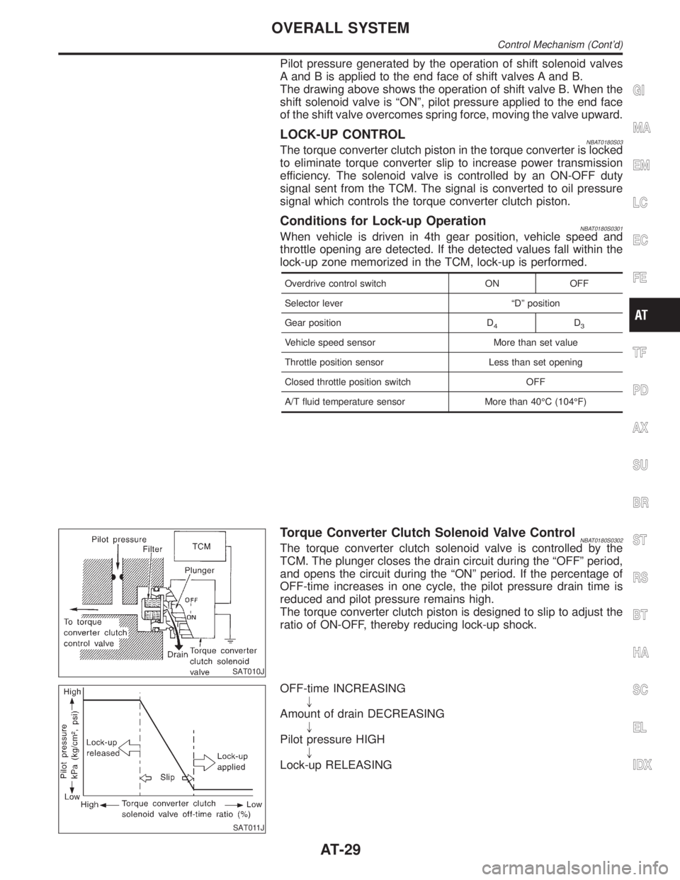
Torque Converter Clutch Solenoid Valve ControlNBAT0180S0302The torque converter clutch solenoid valve is controlled by the
TCM. The plunger closes the drain circuit during the ªOFFº period,
and opens the circuit during the ªONº period. If the percentage of
OFF-time increases in one cycle, the pilot pressure drain time is
reduced and pilot pressure remains high.
The torque converter clutch piston is designed to slip to adjust the
ratio of ON-OFF, thereby reducing lock-up shock.
SAT011J
OFF-time INCREASING
"
Amount of drain DECREASING
"
Pilot pressure HIGH
"
Lock-up RELEASING
GI
MA
EM
LC
EC
FE
TF
PD
AX
SU
BR
ST
RS
BT
HA
SC
EL
IDX
OVERALL SYSTEM
Control Mechanism (Cont'd)
AT-29
Page 64 of 2395
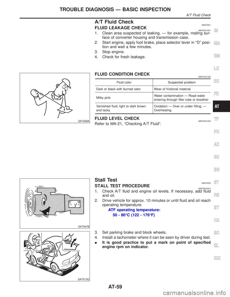
A/T Fluid CheckNBAT0021FLUID LEAKAGE CHECKNBAT0021S011. Clean area suspected of leaking. Ð for example, mating sur-
face of converter housing and transmission case.
2. Start engine, apply foot brake, place selector lever in ªDº posi-
tion and wait a few minutes.
3. Stop engine.
4. Check for fresh leakage.
SAT638A
FLUID CONDITION CHECKNBAT0021S02
Fluid color Suspected problem
Dark or black with burned odor Wear of frictional material
Milky pinkWater contamination Ð Road water
entering through filler tube or breather
Varnished fluid, light to dark brown
and tackyOxidation Ð Over or under filling, Ð
Overheating
FLUID LEVEL CHECKNBAT0021S03Refer to MA-21, ªChecking A/T Fluidº.
SAT647B
Stall TestNBAT0022STALL TEST PROCEDURENBAT0022S011. Check A/T fluid and engine oil levels. If necessary, add fluid
and oil.
2. Drive vehicle for approx. 10 minutes or until fluid and oil reach
operating temperature.
ATF operating temperature:
50 - 80ÉC (122 - 176ÉF)
SAT513G
3. Set parking brake and block wheels.
4. Install a tachometer where it can be seen by driver during test.
IIt is good practice to put a mark on point of specified
engine rpm on indicator.
GI
MA
EM
LC
EC
FE
TF
PD
AX
SU
BR
ST
RS
BT
HA
SC
EL
IDX
TROUBLE DIAGNOSIS Ð BASIC INSPECTION
A/T Fluid Check
AT-59
Page 67 of 2395

SAT209GA
Line Pressure TestNBAT0023ILocation of line pressure test ports.
IAlways replace line pressure plugs as they are self-seal-
ing bolts.
SAT647B
LINE PRESSURE TEST PROCEDURENBAT0023S011. Check A/T fluid and engine oil levels. If necessary, add fluid
and oil.
2. Drive vehicle for approx. 10 minutes or until fluid and oil reach
operating temperature.
ATF operating temperature:
50 - 80ÉC (122 - 176ÉF)
SAT518GB
SAT519GB
3. Install pressure gauge to corresponding line pressure port.
SAT513G
4. Set parking brake and block wheels.
IContinue to depress brake pedal fully while line pressure
test is being performed at stall speed.
TROUBLE DIAGNOSIS Ð BASIC INSPECTION
Line Pressure Test
AT-62
Page 68 of 2395
SAT493G
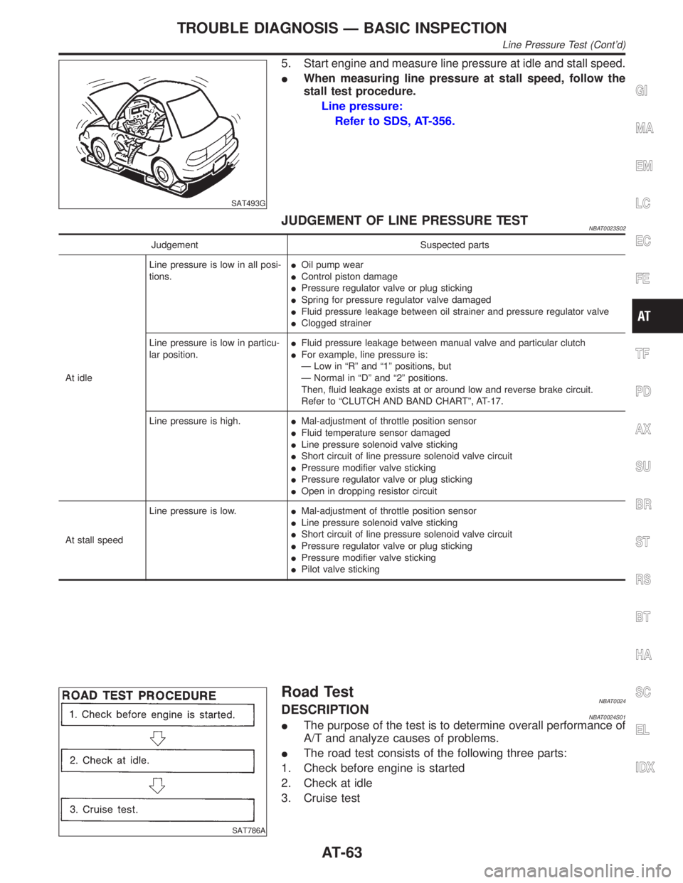
5. Start engine and measure line pressure at idle and stall speed.
IWhen measuring line pressure at stall speed, follow the
stall test procedure.
Line pressure:
Refer to SDS, AT-356.
JUDGEMENT OF LINE PRESSURE TESTNBAT0023S02
Judgement Suspected parts
At idleLine pressure is low in all posi-
tions.IOil pump wear
IControl piston damage
IPressure regulator valve or plug sticking
ISpring for pressure regulator valve damaged
IFluid pressure leakage between oil strainer and pressure regulator valve
IClogged strainer
Line pressure is low in particu-
lar position.IFluid pressure leakage between manual valve and particular clutch
IFor example, line pressure is:
Ð Low in ªRº and ª1º positions, but
Ð Normal in ªDº and ª2º positions.
Then, fluid leakage exists at or around low and reverse brake circuit.
Refer to ªCLUTCH AND BAND CHARTº, AT-17.
Line pressure is high.IMal-adjustment of throttle position sensor
IFluid temperature sensor damaged
ILine pressure solenoid valve sticking
IShort circuit of line pressure solenoid valve circuit
IPressure modifier valve sticking
IPressure regulator valve or plug sticking
IOpen in dropping resistor circuit
At stall speedLine pressure is low.IMal-adjustment of throttle position sensor
ILine pressure solenoid valve sticking
IShort circuit of line pressure solenoid valve circuit
IPressure regulator valve or plug sticking
IPressure modifier valve sticking
IPilot valve sticking
SAT786A
Road TestNBAT0024DESCRIPTIONNBAT0024S01IThe purpose of the test is to determine overall performance of
A/T and analyze causes of problems.
IThe road test consists of the following three parts:
1. Check before engine is started
2. Check at idle
3. Cruise test
GI
MA
EM
LC
EC
FE
TF
PD
AX
SU
BR
ST
RS
BT
HA
SC
EL
IDX
TROUBLE DIAGNOSIS Ð BASIC INSPECTION
Line Pressure Test (Cont'd)
AT-63
Page 76 of 2395

Cruise Test Ð Part 1=NBAT0024S0404
1 CHECK STARTING GEAR (D1) POSITION
1. Drive vehicle for approx. 10 minutes to warm engine oil and ATF up to operating temperature.
ATF operating temperature:
50 - 80ÉC (122 - 176ÉF)
2. Park vehicle on flat surface.
3. Set overdrive control switch to ªONº position.
4. Move selector lever to ªPº position.
SAT001J
5. Start engine.
6. Move selector lever to ªDº position.
SAT952I
7. Accelerate vehicle by constantly depressing accelerator pedal halfway.
SAT953I
8. Does vehicle start from D1?
Read gear position.
YesorNo
Ye s©GO TO 2.
No©Go to ª8. Vehicle Cannot Be Started From D
1º, AT-233.
GI
MA
EM
LC
EC
FE
TF
PD
AX
SU
BR
ST
RS
BT
HA
SC
EL
IDX
TROUBLE DIAGNOSIS Ð BASIC INSPECTION
Road Test (Cont'd)
AT-71
Page 114 of 2395

4 CHECK A/T FLUID TEMPERATURE SENSOR WITH TERMINAL CORD ASSEMBLY
1. Turn ignition switch to ªOFFº position.
2. Disconnect terminal cord assembly connector on the right side of transfer assmebly.
3. Check resistance between terminals 8 and 9 when A/T is cold [20ÉC (68ÉF)].
SAT697I
Is resistance approx. 2.5 kW?
Ye s©GO TO 7.
No©GO TO 5.
5 DETECT MALFUNCTIONING ITEM
1. Remove oil pan.
2. Check the following items:
IA/T fluid temperature sensor
Refer to ªComponent Inspectionº, AT-110.
IHarness of terminal cord assembly for short or open
OK or NG
OK©GO TO 7.
NG©Repair or replace damaged parts.
6 CHECK INPUT SIGNAL OF A/T FLUID TEMPERATURE SENSOR (WITHOUT CONSULT-II)
Without CONSULT-II
1. Start engine.
2. Check voltage between TCM terminal 47 and ground while warming up A/T.
Voltage:
Cold [20ÉC (68ÉF)]®Hot [80ÉC (176ÉF)]:
Approximately 1.5V®0.5V
SAT518J
OK or NG
OK©GO TO 4.
NG©GO TO 3.
GI
MA
EM
LC
EC
FE
TF
PD
AX
SU
BR
ST
RS
BT
HA
SC
EL
IDX
DTC P0710 A/T FLUID TEMPERATURE SENSOR CIRCUIT
Diagnostic Procedure (Cont'd)
AT-109
Page 199 of 2395

4 CHECK A/T FLUID TEMPERATURE SENSOR WITH TERMINAL CORD ASSEMBLY
1. Turn ignition switch to ªOFFº position.
2. Disconnect terminal cord assembly connector on the right side of transfer assmebly.
3. Check resistance between terminals 8 and 9 when A/T is cold [20ÉC (68ÉF)].
SAT697I
Is resistance approx. 2.5 kW?
Ye s©GO TO 7.
No©GO TO 5.
5 DETECT MALFUNCTIONING ITEM
1. Remove oil pan.
2. Check the following items:
IA/T fluid temperature sensor
Refer to ªComponent Inspectionº, AT-110.
IHarness of terminal cord assembly for short or open
OK or NG
OK©GO TO 7.
NG©Repair or replace damaged parts.
6 CHECK INPUT SIGNAL OF A/T FLUID TEMPERATURE SENSOR (WITHOUT CONSULT-II)
Without CONSULT-II
1. Start engine.
2. Check voltage between TCM terminal 47 and ground while warming up A/T.
Voltage:
Cold [20ÉC (68ÉF)]®Hot [80ÉC (176ÉF)]:
Approximately 1.5V®0.5V
SAT518J
OK or NG
OK©GO TO 4.
NG©GO TO 3.
DTC BATT/FLUID TEMP SEN (A/T FLUID TEMP SENSOR CIRCUIT AND TCM
POWER SOURCE)
Diagnostic Procedure (Cont'd)
AT-194
Page 278 of 2395

SAT359I
Control Valve Assembly and AccumulatorsNBAT0100REMOVALNBAT0100S011. Remove exhaust front tube.
2. Remove oil pan and gasket and drain ATF.
SAT073BA
3. Remove A/T fluid temperature sensor if necessary.
4. Remove oil strainer.
SAT353B
5. Remove control valve assembly by removing fixing bolts and
disconnecting harness connector.
Bolt length and location
Bolt symbolmm (in)
A 33 (1.30)
B 45 (1.77)
6. Remove solenoids and valves from valve body if necessary.
7. Remove terminal cord assembly if necessary.
SAT074BA
8. Remove accumulatorA, B, CandDby applying compressed
air if necessary.
IHold each piston with rag.
9. Reinstall any part removed.
IAlways use new sealing parts.
GI
MA
EM
LC
EC
FE
TF
PD
AX
SU
BR
ST
RS
BT
HA
SC
EL
IDX
ON-VEHICLE SERVICE
Control Valve Assembly and Accumulators
AT-273
Page 292 of 2395
SAT171B
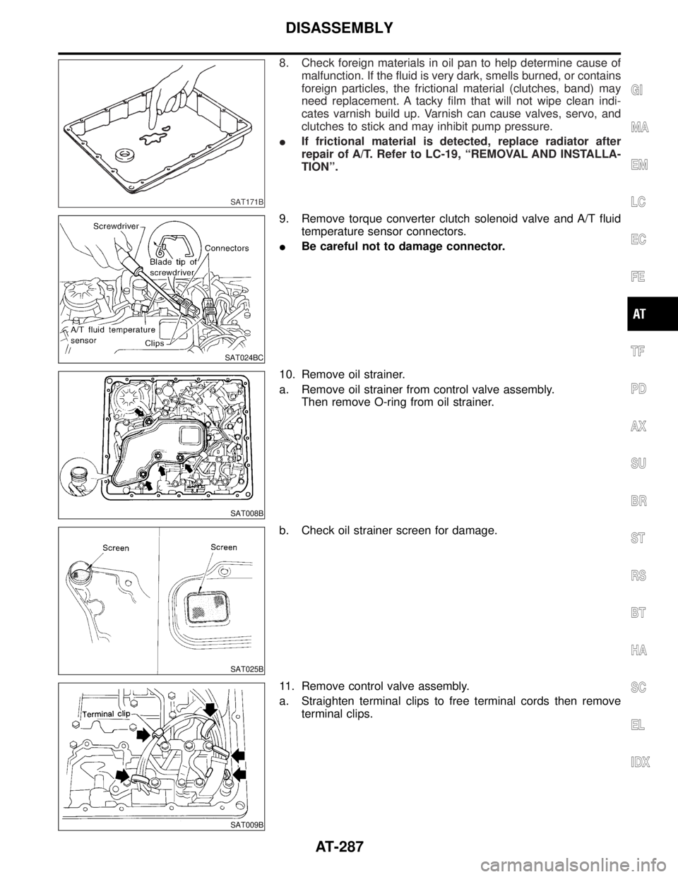
8. Check foreign materials in oil pan to help determine cause of
malfunction. If the fluid is very dark, smells burned, or contains
foreign particles, the frictional material (clutches, band) may
need replacement. A tacky film that will not wipe clean indi-
cates varnish build up. Varnish can cause valves, servo, and
clutches to stick and may inhibit pump pressure.
IIf frictional material is detected, replace radiator after
repair of A/T. Refer to LC-19, ªREMOVAL AND INSTALLA-
TIONº.
SAT024BC
9. Remove torque converter clutch solenoid valve and A/T fluid
temperature sensor connectors.
IBe careful not to damage connector.
SAT008B
10. Remove oil strainer.
a. Remove oil strainer from control valve assembly.
Then remove O-ring from oil strainer.
SAT025B
b. Check oil strainer screen for damage.
SAT009B
11. Remove control valve assembly.
a. Straighten terminal clips to free terminal cords then remove
terminal clips.
GI
MA
EM
LC
EC
FE
TF
PD
AX
SU
BR
ST
RS
BT
HA
SC
EL
IDX
DISASSEMBLY
AT-287