oil pressure INFINITI QX4 2001 Factory Service Manual
[x] Cancel search | Manufacturer: INFINITI, Model Year: 2001, Model line: QX4, Model: INFINITI QX4 2001Pages: 2395, PDF Size: 43.2 MB
Page 8 of 2395
19. A/T Does Not Shift: 22-> 11, When Selector
Lever²2²->²1²Position .........................................255
20. Vehicle Does Not Decelerate By Engine
Brake........................................................................256
21. TCM Self-diagnosis Does Not Activate (PNP,
Overdrive Control and Throttle Position Switches
Circuit Checks) ........................................................257
A/T SHIFT LOCK SYSTEM.........................................265
Description ...............................................................265
Wiring Diagram - SHIFT -........................................266
Diagnostic Procedure ..............................................267
KEY INTERLOCK CABLE..........................................271
Components.............................................................271
Removal ...................................................................271
Installation ................................................................272
ON-VEHICLE SERVICE..............................................273
Control Valve Assembly and Accumulators .............273
Revolution Sensor Replacement .............................274
Turbine Revolution Sensor Replacement................274
Rear Oil Seal Replacement .....................................274
Rear Oil Seal and Companion Flange Oil Seal
Replacement ............................................................275
Parking Components Inspection..............................275
Park/Neutral Position Switch Adjustment ................276
Manual Control Linkage Adjustment........................276
REMOVAL AND INSTALLATION...............................277
Removal ...................................................................277
Installation ................................................................278
OVERHAUL.................................................................281
Components.............................................................281
Oil Channel ..............................................................284
Locations of Needle Bearings, Thrust Washers
and Snap Rings .......................................................285
DISASSEMBLY............................................................286
REPAIR FOR COMPONENT PARTS.........................297Oil Pump ..................................................................297
Control Valve Assembly ...........................................301
Control Valve Upper Body .......................................307
Control Valve Lower Body .......................................312
Reverse Clutch ........................................................314
High Clutch ..............................................................317
Forward and Overrun Clutches ...............................320
Low & Reverse Brake..............................................324
Forward Clutch Drum Assembly ..............................328
Rear Internal Gear and Forward Clutch Hub ..........330
Band Servo Piston Assembly ..................................333
Parking Pawl Components ......................................337
ASSEMBLY..................................................................339
Assembly (1) ............................................................339
Adjustment ...............................................................347
Assembly (2) ............................................................349
SERVICE DATA AND SPECIFICATIONS (SDS).......356
General Specifications .............................................356
Shift Schedule..........................................................356
Stall Revolution ........................................................356
Line Pressure...........................................................356
Return Springs .........................................................357
Accumulator O-ring ..................................................358
Clutches and Brakes ...............................................358
Oil Pump and Low One-way Clutch ........................360
Total End Play..........................................................360
Reverse Clutch Drum End Play ..............................361
Removal and Installation .........................................361
Shift Solenoid Valves ...............................................361
Solenoid Valves .......................................................361
A/T Fluid Temperature Sensor.................................361
Turbine Revolution Sensor ......................................361
Revolution Sensor ...................................................362
Dropping Resistor ....................................................362GI
MA
EM
LC
EC
FE
TF
PD
AX
SU
BR
ST
RS
BT
HA
SC
EL
IDX
CONTENTS(Cont'd)
AT-3
Page 15 of 2395
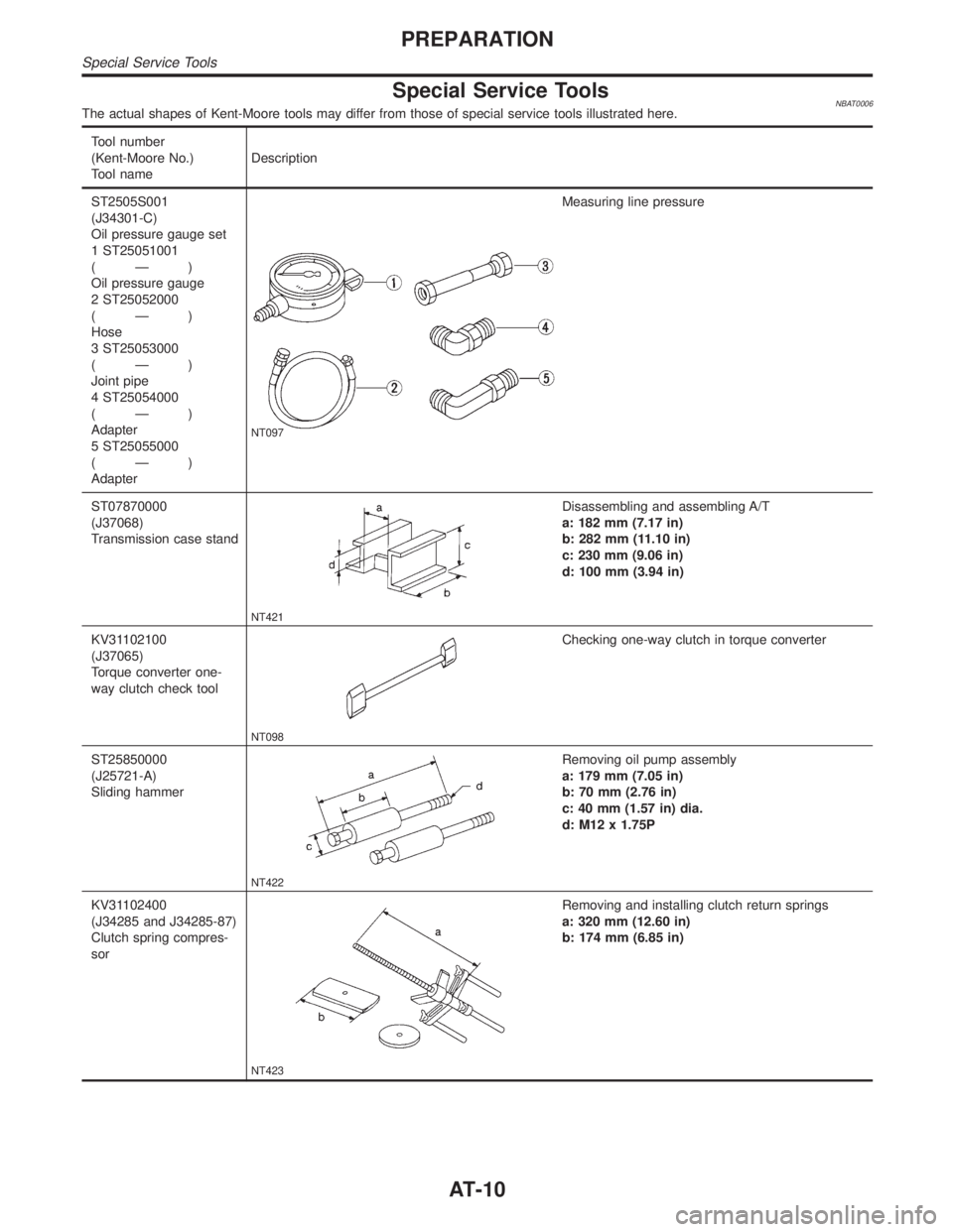
Special Service ToolsNBAT0006The actual shapes of Kent-Moore tools may differ from those of special service tools illustrated here.
Tool number
(Kent-Moore No.)
Tool nameDescription
ST2505S001
(J34301-C)
Oil pressure gauge set
1 ST25051001
(Ð)
Oil pressure gauge
2 ST25052000
(Ð)
Hose
3 ST25053000
(Ð)
Joint pipe
4 ST25054000
(Ð)
Adapter
5 ST25055000
(Ð)
Adapter
NT097
Measuring line pressure
ST07870000
(J37068)
Transmission case stand
NT421
Disassembling and assembling A/T
a: 182 mm (7.17 in)
b: 282 mm (11.10 in)
c: 230 mm (9.06 in)
d: 100 mm (3.94 in)
KV31102100
(J37065)
Torque converter one-
way clutch check tool
NT098
Checking one-way clutch in torque converter
ST25850000
(J25721-A)
Sliding hammer
NT422
Removing oil pump assembly
a: 179 mm (7.05 in)
b: 70 mm (2.76 in)
c: 40 mm (1.57 in) dia.
d: M12 x 1.75P
KV31102400
(J34285 and J34285-87)
Clutch spring compres-
sor
NT423
Removing and installing clutch return springs
a: 320 mm (12.60 in)
b: 174 mm (6.85 in)
PREPARATION
Special Service Tools
AT-10
Page 22 of 2395
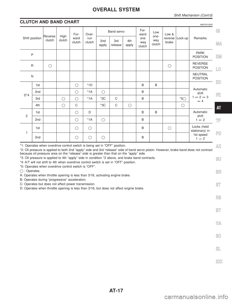
CLUTCH AND BAND CHARTNBAT0012S03
Shift positionReverse
clutchHigh
clutchFor-
ward
clutchOver-
run
clutchBand servoFor-
ward
one
-way
clutchLow
one-
way
clutchLow &
reverse
brakeLock-up Remarks
2nd
apply3rd
release4th
apply
PPARK
POSITION
RqqREVERSE
POSITION
NNEUTRAL
POSITION
D*41stq*1D B B
Automatic
shift
1k2k3
k4 2ndq*1AqB
3rdqq*1A *2C C B *5q
4thqC *3C Cqq
21stqDBBAutomatic
shift
1k2 2ndq*1AqB
11stqqBqLocks (held
stationary) in
1st speed
1g2 2ndqqqB
*1: Operates when overdrive control switch is being set in ªOFFº position.
*2: Oil pressure is applied to both 2nd ªapplyº side and 3rd ªreleaseº side of band servo piston. However, brake band does not contract
because oil pressure area on the ªreleaseº side is greater than that on the ªapplyº side.
*3: Oil pressure is applied to 4th ªapplyº side in condition *2 above, and brake band contracts.
*4: A/T will not shift to 4th when overdrive control switch is set in ªOFFº position.
*5: Operates when overdrive control switch is ªOFFº.
q: Operates.
A: Operates when throttle opening is less than 3/16, activating engine brake.
B: Operates during ªprogressiveº acceleration.
C: Operates but does not affect power transmission.
D: Operates when throttle opening is less than 3/16, but does not affect engine brake.
GI
MA
EM
LC
EC
FE
TF
PD
AX
SU
BR
ST
RS
BT
HA
SC
EL
IDX
OVERALL SYSTEM
Shift Mechanism (Cont'd)
AT-17
Page 34 of 2395
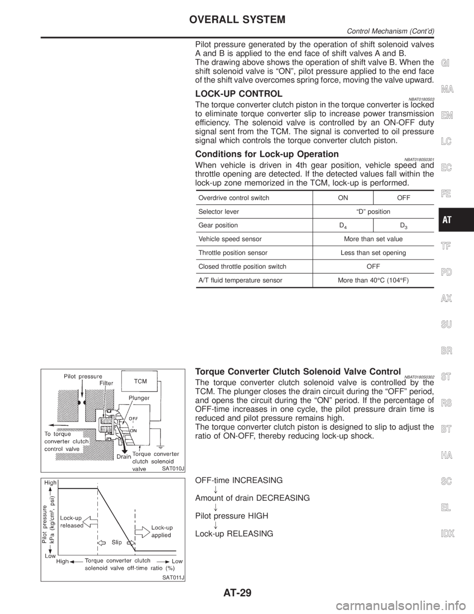
Pilot pressure generated by the operation of shift solenoid valves
A and B is applied to the end face of shift valves A and B.
The drawing above shows the operation of shift valve B. When the
shift solenoid valve is ªONº, pilot pressure applied to the end face
of the shift valve overcomes spring force, moving the valve upward.
LOCK-UP CONTROLNBAT0180S03The torque converter clutch piston in the torque converter is locked
to eliminate torque converter slip to increase power transmission
efficiency. The solenoid valve is controlled by an ON-OFF duty
signal sent from the TCM. The signal is converted to oil pressure
signal which controls the torque converter clutch piston.
Conditions for Lock-up OperationNBAT0180S0301When vehicle is driven in 4th gear position, vehicle speed and
throttle opening are detected. If the detected values fall within the
lock-up zone memorized in the TCM, lock-up is performed.
Overdrive control switch ON OFF
Selector lever ªDº position
Gear position D
4D3
Vehicle speed sensor More than set value
Throttle position sensor Less than set opening
Closed throttle position switch OFF
A/T fluid temperature sensor More than 40ÉC (104ÉF)
SAT010J
Torque Converter Clutch Solenoid Valve ControlNBAT0180S0302The torque converter clutch solenoid valve is controlled by the
TCM. The plunger closes the drain circuit during the ªOFFº period,
and opens the circuit during the ªONº period. If the percentage of
OFF-time increases in one cycle, the pilot pressure drain time is
reduced and pilot pressure remains high.
The torque converter clutch piston is designed to slip to adjust the
ratio of ON-OFF, thereby reducing lock-up shock.
SAT011J
OFF-time INCREASING
"
Amount of drain DECREASING
"
Pilot pressure HIGH
"
Lock-up RELEASING
GI
MA
EM
LC
EC
FE
TF
PD
AX
SU
BR
ST
RS
BT
HA
SC
EL
IDX
OVERALL SYSTEM
Control Mechanism (Cont'd)
AT-29
Page 36 of 2395
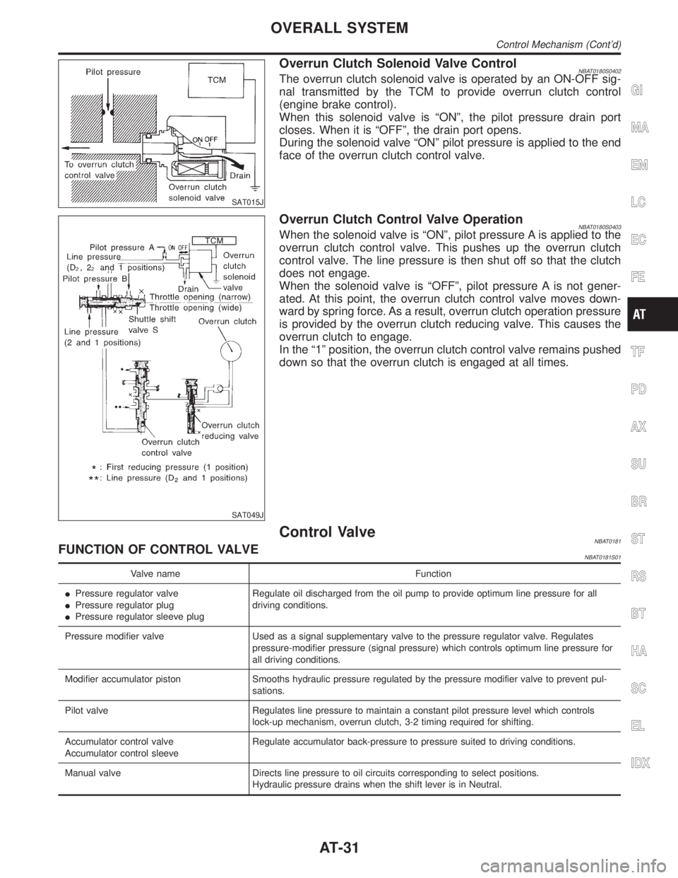
SAT015J
Overrun Clutch Solenoid Valve ControlNBAT0180S0402The overrun clutch solenoid valve is operated by an ON-OFF sig-
nal transmitted by the TCM to provide overrun clutch control
(engine brake control).
When this solenoid valve is ªONº, the pilot pressure drain port
closes. When it is ªOFFº, the drain port opens.
During the solenoid valve ªONº pilot pressure is applied to the end
face of the overrun clutch control valve.
SAT049J
Overrun Clutch Control Valve OperationNBAT0180S0403When the solenoid valve is ªONº, pilot pressure A is applied to the
overrun clutch control valve. This pushes up the overrun clutch
control valve. The line pressure is then shut off so that the clutch
does not engage.
When the solenoid valve is ªOFFº, pilot pressure A is not gener-
ated. At this point, the overrun clutch control valve moves down-
ward by spring force. As a result, overrun clutch operation pressure
is provided by the overrun clutch reducing valve. This causes the
overrun clutch to engage.
In the ª1º position, the overrun clutch control valve remains pushed
down so that the overrun clutch is engaged at all times.
Control ValveNBAT0181FUNCTION OF CONTROL VALVENBAT0181S01
Valve name Function
IPressure regulator valve
IPressure regulator plug
IPressure regulator sleeve plugRegulate oil discharged from the oil pump to provide optimum line pressure for all
driving conditions.
Pressure modifier valve Used as a signal supplementary valve to the pressure regulator valve. Regulates
pressure-modifier pressure (signal pressure) which controls optimum line pressure for
all driving conditions.
Modifier accumulator piston Smooths hydraulic pressure regulated by the pressure modifier valve to prevent pul-
sations.
Pilot valve Regulates line pressure to maintain a constant pilot pressure level which controls
lock-up mechanism, overrun clutch, 3-2 timing required for shifting.
Accumulator control valve
Accumulator control sleeveRegulate accumulator back-pressure to pressure suited to driving conditions.
Manual valve Directs line pressure to oil circuits corresponding to select positions.
Hydraulic pressure drains when the shift lever is in Neutral.
GI
MA
EM
LC
EC
FE
TF
PD
AX
SU
BR
ST
RS
BT
HA
SC
EL
IDX
OVERALL SYSTEM
Control Mechanism (Cont'd)
AT-31
Page 37 of 2395
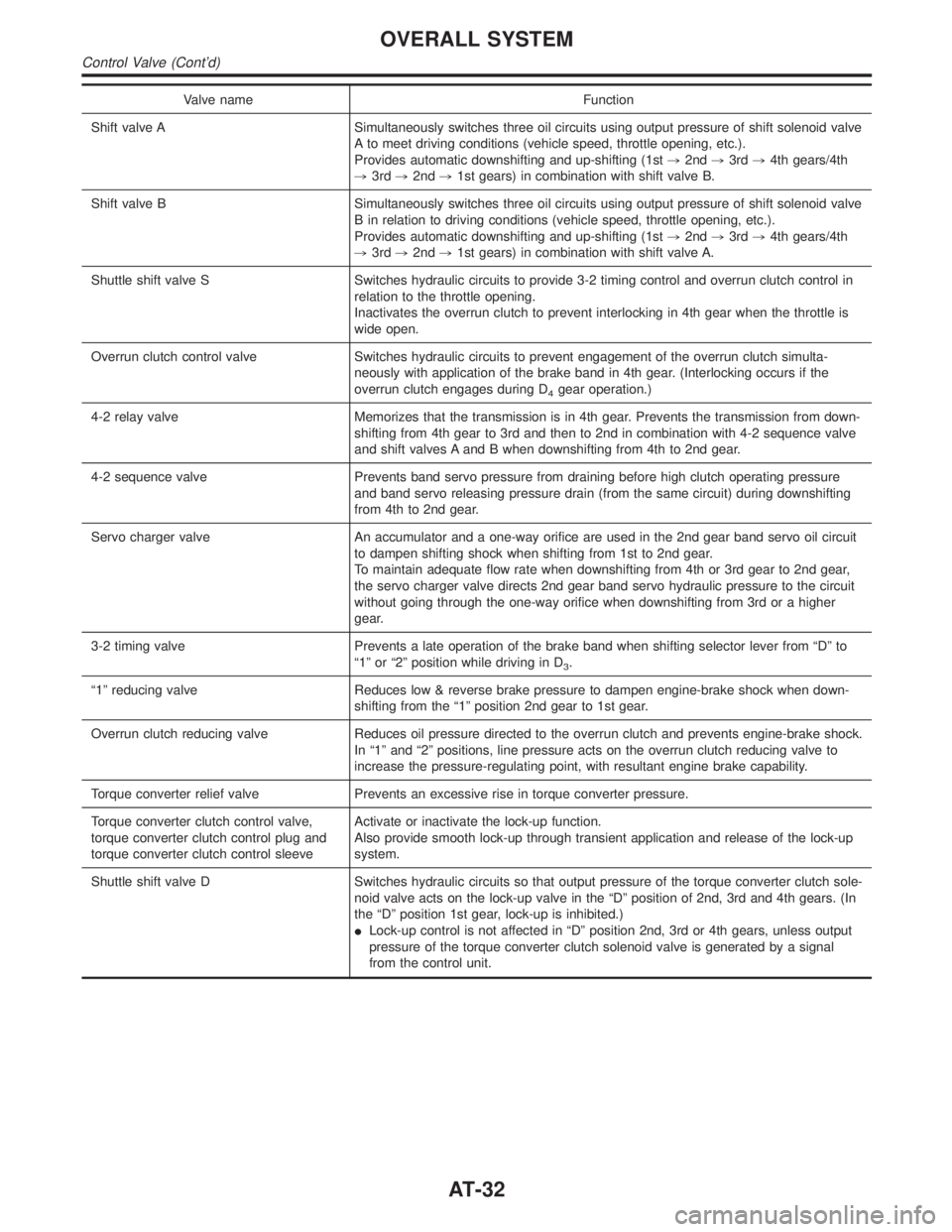
Valve name Function
Shift valve A Simultaneously switches three oil circuits using output pressure of shift solenoid valve
A to meet driving conditions (vehicle speed, throttle opening, etc.).
Provides automatic downshifting and up-shifting (1st,2nd,3rd,4th gears/4th
,3rd,2nd,1st gears) in combination with shift valve B.
Shift valve B Simultaneously switches three oil circuits using output pressure of shift solenoid valve
B in relation to driving conditions (vehicle speed, throttle opening, etc.).
Provides automatic downshifting and up-shifting (1st,2nd,3rd,4th gears/4th
,3rd,2nd,1st gears) in combination with shift valve A.
Shuttle shift valve S Switches hydraulic circuits to provide 3-2 timing control and overrun clutch control in
relation to the throttle opening.
Inactivates the overrun clutch to prevent interlocking in 4th gear when the throttle is
wide open.
Overrun clutch control valve Switches hydraulic circuits to prevent engagement of the overrun clutch simulta-
neously with application of the brake band in 4th gear. (Interlocking occurs if the
overrun clutch engages during D
4gear operation.)
4-2 relay valve Memorizes that the transmission is in 4th gear. Prevents the transmission from down-
shifting from 4th gear to 3rd and then to 2nd in combination with 4-2 sequence valve
and shift valves A and B when downshifting from 4th to 2nd gear.
4-2 sequence valve Prevents band servo pressure from draining before high clutch operating pressure
and band servo releasing pressure drain (from the same circuit) during downshifting
from 4th to 2nd gear.
Servo charger valve An accumulator and a one-way orifice are used in the 2nd gear band servo oil circuit
to dampen shifting shock when shifting from 1st to 2nd gear.
To maintain adequate flow rate when downshifting from 4th or 3rd gear to 2nd gear,
the servo charger valve directs 2nd gear band servo hydraulic pressure to the circuit
without going through the one-way orifice when downshifting from 3rd or a higher
gear.
3-2 timing valve Prevents a late operation of the brake band when shifting selector lever from ªDº to
ª1º or ª2º position while driving in D
3.
ª1º reducing valve Reduces low & reverse brake pressure to dampen engine-brake shock when down-
shifting from the ª1º position 2nd gear to 1st gear.
Overrun clutch reducing valve Reduces oil pressure directed to the overrun clutch and prevents engine-brake shock.
In ª1º and ª2º positions, line pressure acts on the overrun clutch reducing valve to
increase the pressure-regulating point, with resultant engine brake capability.
Torque converter relief valve Prevents an excessive rise in torque converter pressure.
Torque converter clutch control valve,
torque converter clutch control plug and
torque converter clutch control sleeveActivate or inactivate the lock-up function.
Also provide smooth lock-up through transient application and release of the lock-up
system.
Shuttle shift valve D Switches hydraulic circuits so that output pressure of the torque converter clutch sole-
noid valve acts on the lock-up valve in the ªDº position of 2nd, 3rd and 4th gears. (In
the ªDº position 1st gear, lock-up is inhibited.)
ILock-up control is not affected in ªDº position 2nd, 3rd or 4th gears, unless output
pressure of the torque converter clutch solenoid valve is generated by a signal
from the control unit.
OVERALL SYSTEM
Control Valve (Cont'd)
AT-32
Page 67 of 2395

SAT209GA
Line Pressure TestNBAT0023ILocation of line pressure test ports.
IAlways replace line pressure plugs as they are self-seal-
ing bolts.
SAT647B
LINE PRESSURE TEST PROCEDURENBAT0023S011. Check A/T fluid and engine oil levels. If necessary, add fluid
and oil.
2. Drive vehicle for approx. 10 minutes or until fluid and oil reach
operating temperature.
ATF operating temperature:
50 - 80ÉC (122 - 176ÉF)
SAT518GB
SAT519GB
3. Install pressure gauge to corresponding line pressure port.
SAT513G
4. Set parking brake and block wheels.
IContinue to depress brake pedal fully while line pressure
test is being performed at stall speed.
TROUBLE DIAGNOSIS Ð BASIC INSPECTION
Line Pressure Test
AT-62
Page 68 of 2395
SAT493G
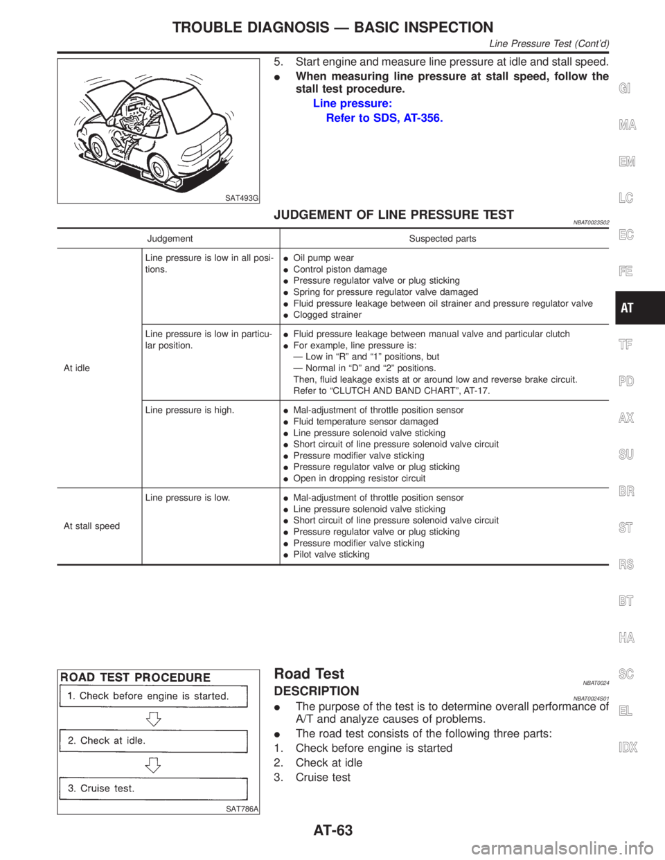
5. Start engine and measure line pressure at idle and stall speed.
IWhen measuring line pressure at stall speed, follow the
stall test procedure.
Line pressure:
Refer to SDS, AT-356.
JUDGEMENT OF LINE PRESSURE TESTNBAT0023S02
Judgement Suspected parts
At idleLine pressure is low in all posi-
tions.IOil pump wear
IControl piston damage
IPressure regulator valve or plug sticking
ISpring for pressure regulator valve damaged
IFluid pressure leakage between oil strainer and pressure regulator valve
IClogged strainer
Line pressure is low in particu-
lar position.IFluid pressure leakage between manual valve and particular clutch
IFor example, line pressure is:
Ð Low in ªRº and ª1º positions, but
Ð Normal in ªDº and ª2º positions.
Then, fluid leakage exists at or around low and reverse brake circuit.
Refer to ªCLUTCH AND BAND CHARTº, AT-17.
Line pressure is high.IMal-adjustment of throttle position sensor
IFluid temperature sensor damaged
ILine pressure solenoid valve sticking
IShort circuit of line pressure solenoid valve circuit
IPressure modifier valve sticking
IPressure regulator valve or plug sticking
IOpen in dropping resistor circuit
At stall speedLine pressure is low.IMal-adjustment of throttle position sensor
ILine pressure solenoid valve sticking
IShort circuit of line pressure solenoid valve circuit
IPressure regulator valve or plug sticking
IPressure modifier valve sticking
IPilot valve sticking
SAT786A
Road TestNBAT0024DESCRIPTIONNBAT0024S01IThe purpose of the test is to determine overall performance of
A/T and analyze causes of problems.
IThe road test consists of the following three parts:
1. Check before engine is started
2. Check at idle
3. Cruise test
GI
MA
EM
LC
EC
FE
TF
PD
AX
SU
BR
ST
RS
BT
HA
SC
EL
IDX
TROUBLE DIAGNOSIS Ð BASIC INSPECTION
Line Pressure Test (Cont'd)
AT-63
Page 91 of 2395

Items Symptom Condition Diagnostic Item Reference Page
Slips/Will Not
EngageVehicle will not
run in D, 1, 2
positions (but
runs in R posi-
tion). Clutch slips.
Very poor accel-
eration.
AT-230ON vehicle1. Fluid level AT-59
2. Line pressure test AT-62
3. Line pressure solenoid valve AT-162
4. Control valve assembly AT-273
5. Accumulator N-D AT-273
OFF vehicle6. Reverse clutch AT-314
7. High clutch AT-317
8. Forward clutch AT-320
9. Forward one-way clutch AT-330
10. Low one-way clutch AT-328
Clutches or
brakes slip some-
what in starting.ON vehicle1. Fluid level AT-59
2. Manual control linkage adjustment AT-276
3. Throttle position sensor (Adjustment) EC-174
4. Line pressure test AT-62
5. Line pressure solenoid valve AT-162
6. Control valve assembly AT-273
7. Accumulator N-D AT-273
OFF vehicle8. Forward clutch AT-320
9. Reverse clutch AT-314
10. Low & reverse brake AT-324
11. Oil pump AT-297
12. Torque converter AT-286
No creep at all.
AT-227, 230ON vehicle1. Fluid level AT-59
2. Line pressure test AT-62
3. Control valve assembly AT-273
OFF vehicle4. Forward clutch AT-320
5. Oil pump AT-297
6. Torque converter AT-286
Almost no shock
or clutches slip-
ping in change
from D
1to D2.ON vehicle1. Fluid level AT-59
2. Throttle position sensor (Adjustment) EC-174
3. Line pressure test AT-62
4. Accumulator servo release AT-273
5. Control valve assembly AT-273
OFF vehicle 6. Brake band AT-333
TROUBLE DIAGNOSIS Ð GENERAL DESCRIPTION
Symptom Chart (Cont'd)
AT-86
Page 93 of 2395

Items Symptom Condition Diagnostic Item Reference Page
Slips/Will Not
EngageRaces extremely
fast or slips in
changing from D
4or D3to D1when
depressing pedal.ON vehicle1. Fluid level AT-59
2. Throttle position sensor (Adjustment) EC-174
3. Line pressure test AT-62
4. Line pressure solenoid valve AT-162
5. Control valve assembly AT-273
OFF vehicle6. Forward clutch AT-320
7. Forward one-way clutch AT-330
8. Low one-way clutch AT-328
Vehicle will not
run in any posi-
tion.ON vehicle1. Fluid level AT-59
2. Manual control linkage adjustment AT-276
3. Line pressure test AT-62
4. Line pressure solenoid valve AT-162
OFF vehicle5. Oil pump AT-297
6. High clutch AT-317
7. Brake band AT-333
8. Low & reverse brake AT-324
9. Torque converter AT-286
10. Parking pawl components AT-337
NOT USEDEngine cannot be
started in P and N
positions.
AT-221ON vehicle1. Ignition switch and starter EL-9, and SC-10
2. Manual control linkage adjustment AT-276
3. Park/neutral position (PNP) switch
adjustmentAT-276
Engine starts in
positions other
than P and N.
AT-221ON vehicle1. Manual control linkage adjustment AT-276
2. Park/neutral position (PNP) switch
adjustmentAT-276
Transmission
noise in P and N
positions.ON vehicle1. Fluid level AT-59
2. Line pressure test AT-62
3. Throttle position sensor (Adjustment) EC-174
4. Vehicle speed sensor´A/T (Revolution
sensor) and vehicle speed sensor´MTRAT- 111 , 1 9 7
5. Engine speed signal AT-116
OFF vehicle6. Oil pump AT-297
7. Torque converter AT-286
Vehicle moves
when changing
into P position or
parking gear does
not disengage
when shifted out
of P position.
AT-222ON vehicle 1. Manual control linkage adjustment AT-276
OFF vehicle 2. Parking pawl components AT-337
TROUBLE DIAGNOSIS Ð GENERAL DESCRIPTION
Symptom Chart (Cont'd)
AT-88