weight INFINITI QX4 2001 Factory Service Manual
[x] Cancel search | Manufacturer: INFINITI, Model Year: 2001, Model line: QX4, Model: INFINITI QX4 2001Pages: 2395, PDF Size: 43.2 MB
Page 12 of 2395
SEF291H
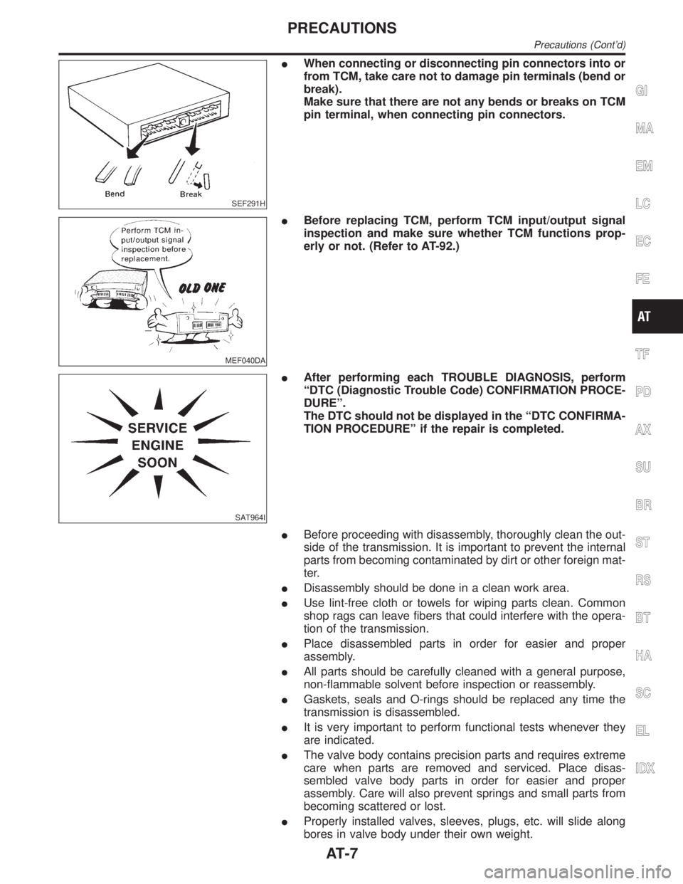
IWhen connecting or disconnecting pin connectors into or
from TCM, take care not to damage pin terminals (bend or
break).
Make sure that there are not any bends or breaks on TCM
pin terminal, when connecting pin connectors.
MEF040DA
IBefore replacing TCM, perform TCM input/output signal
inspection and make sure whether TCM functions prop-
erly or not. (Refer to AT-92.)
SAT964I
IAfter performing each TROUBLE DIAGNOSIS, perform
ªDTC (Diagnostic Trouble Code) CONFIRMATION PROCE-
DUREº.
The DTC should not be displayed in the ªDTC CONFIRMA-
TION PROCEDUREº if the repair is completed.
IBefore proceeding with disassembly, thoroughly clean the out-
side of the transmission. It is important to prevent the internal
parts from becoming contaminated by dirt or other foreign mat-
ter.
IDisassembly should be done in a clean work area.
IUse lint-free cloth or towels for wiping parts clean. Common
shop rags can leave fibers that could interfere with the opera-
tion of the transmission.
IPlace disassembled parts in order for easier and proper
assembly.
IAll parts should be carefully cleaned with a general purpose,
non-flammable solvent before inspection or reassembly.
IGaskets, seals and O-rings should be replaced any time the
transmission is disassembled.
IIt is very important to perform functional tests whenever they
are indicated.
IThe valve body contains precision parts and requires extreme
care when parts are removed and serviced. Place disas-
sembled valve body parts in order for easier and proper
assembly. Care will also prevent springs and small parts from
becoming scattered or lost.
IProperly installed valves, sleeves, plugs, etc. will slide along
bores in valve body under their own weight.
GI
MA
EM
LC
EC
FE
TF
PD
AX
SU
BR
ST
RS
BT
HA
SC
EL
IDX
PRECAUTIONS
Precautions (Cont'd)
AT-7
Page 21 of 2395
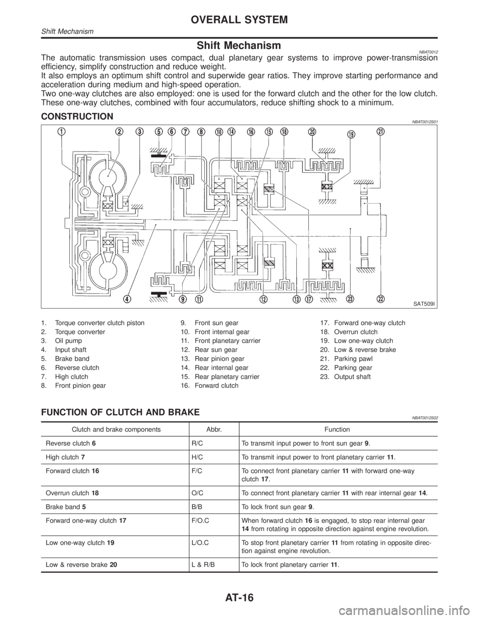
Shift MechanismNBAT0012The automatic transmission uses compact, dual planetary gear systems to improve power-transmission
efficiency, simplify construction and reduce weight.
It also employs an optimum shift control and superwide gear ratios. They improve starting performance and
acceleration during medium and high-speed operation.
Two one-way clutches are also employed: one is used for the forward clutch and the other for the low clutch.
These one-way clutches, combined with four accumulators, reduce shifting shock to a minimum.
CONSTRUCTIONNBAT0012S01
SAT509I
1. Torque converter clutch piston
2. Torque converter
3. Oil pump
4. Input shaft
5. Brake band
6. Reverse clutch
7. High clutch
8. Front pinion gear9. Front sun gear
10. Front internal gear
11. Front planetary carrier
12. Rear sun gear
13. Rear pinion gear
14. Rear internal gear
15. Rear planetary carrier
16. Forward clutch17. Forward one-way clutch
18. Overrun clutch
19. Low one-way clutch
20. Low & reverse brake
21. Parking pawl
22. Parking gear
23. Output shaft
FUNCTION OF CLUTCH AND BRAKENBAT0012S02
Clutch and brake components Abbr. Function
Reverse clutch6R/C To transmit input power to front sun gear9.
High clutch7H/C To transmit input power to front planetary carrier11.
Forward clutch16F/C To connect front planetary carrier11with forward one-way
clutch17.
Overrun clutch18O/C To connect front planetary carrier11with rear internal gear14.
Brake band5B/B To lock front sun gear9.
Forward one-way clutch17F/O.C When forward clutch16is engaged, to stop rear internal gear
14from rotating in opposite direction against engine revolution.
Low one-way clutch19L/O.C To stop front planetary carrier11from rotating in opposite direc-
tion against engine revolution.
Low & reverse brake20L & R/B To lock front planetary carrier11.
OVERALL SYSTEM
Shift Mechanism
AT-16
Page 129 of 2395
Diagnostic ProcedureNBAT0040
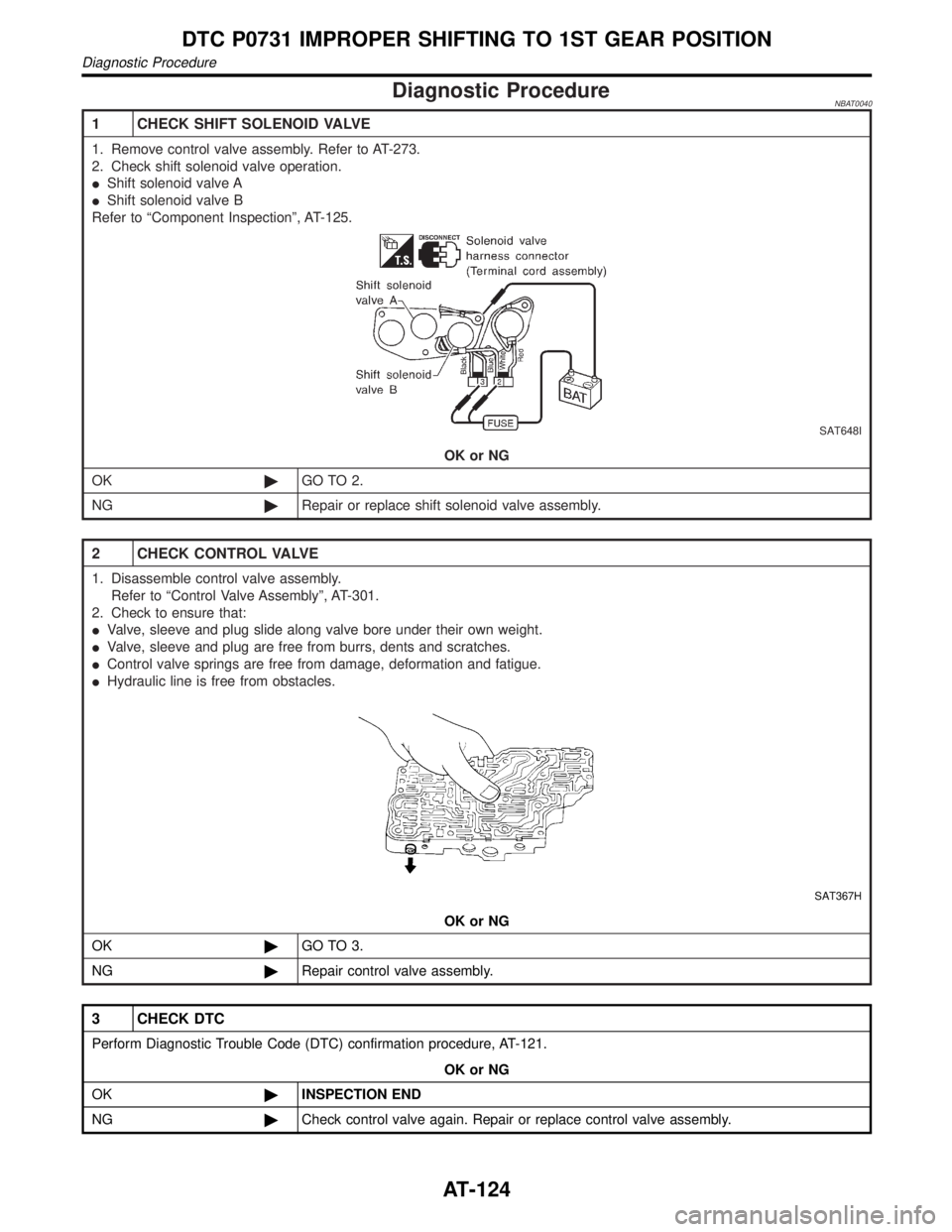
1 CHECK SHIFT SOLENOID VALVE
1. Remove control valve assembly. Refer to AT-273.
2. Check shift solenoid valve operation.
IShift solenoid valve A
IShift solenoid valve B
Refer to ªComponent Inspectionº, AT-125.
SAT648I
OK or NG
OK©GO TO 2.
NG©Repair or replace shift solenoid valve assembly.
2 CHECK CONTROL VALVE
1. Disassemble control valve assembly.
Refer to ªControl Valve Assemblyº, AT-301.
2. Check to ensure that:
IValve, sleeve and plug slide along valve bore under their own weight.
IValve, sleeve and plug are free from burrs, dents and scratches.
IControl valve springs are free from damage, deformation and fatigue.
IHydraulic line is free from obstacles.
SAT367H
OK or NG
OK©GO TO 3.
NG©Repair control valve assembly.
3 CHECK DTC
Perform Diagnostic Trouble Code (DTC) confirmation procedure, AT-121.
OK or NG
OK©INSPECTION END
NG©Check control valve again. Repair or replace control valve assembly.
DTC P0731 IMPROPER SHIFTING TO 1ST GEAR POSITION
Diagnostic Procedure
AT-124
Page 135 of 2395
Diagnostic ProcedureNBAT0043
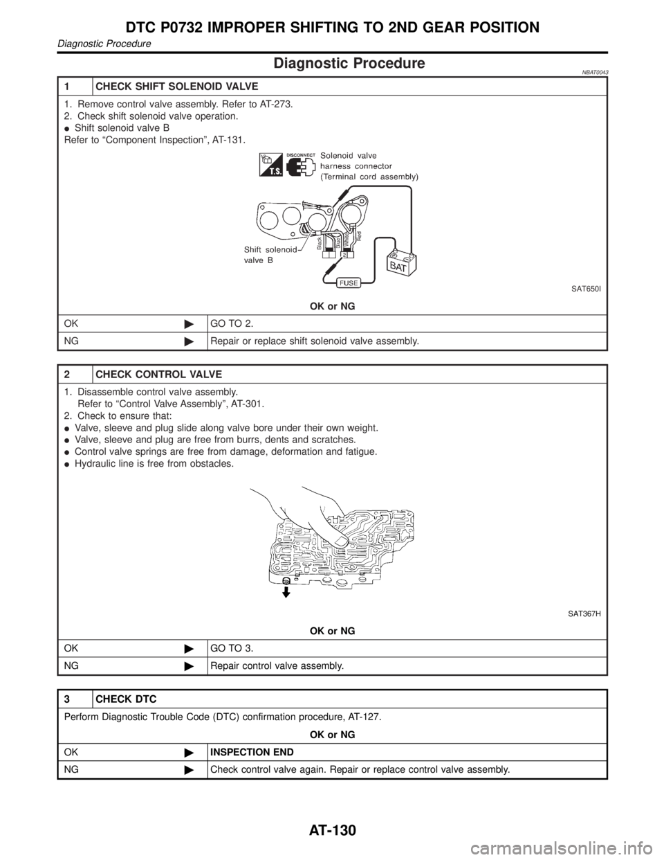
1 CHECK SHIFT SOLENOID VALVE
1. Remove control valve assembly. Refer to AT-273.
2. Check shift solenoid valve operation.
IShift solenoid valve B
Refer to ªComponent Inspectionº, AT-131.
SAT650I
OK or NG
OK©GO TO 2.
NG©Repair or replace shift solenoid valve assembly.
2 CHECK CONTROL VALVE
1. Disassemble control valve assembly.
Refer to ªControl Valve Assemblyº, AT-301.
2. Check to ensure that:
IValve, sleeve and plug slide along valve bore under their own weight.
IValve, sleeve and plug are free from burrs, dents and scratches.
IControl valve springs are free from damage, deformation and fatigue.
IHydraulic line is free from obstacles.
SAT367H
OK or NG
OK©GO TO 3.
NG©Repair control valve assembly.
3 CHECK DTC
Perform Diagnostic Trouble Code (DTC) confirmation procedure, AT-127.
OK or NG
OK©INSPECTION END
NG©Check control valve again. Repair or replace control valve assembly.
DTC P0732 IMPROPER SHIFTING TO 2ND GEAR POSITION
Diagnostic Procedure
AT-130
Page 141 of 2395
Diagnostic ProcedureNBAT0046
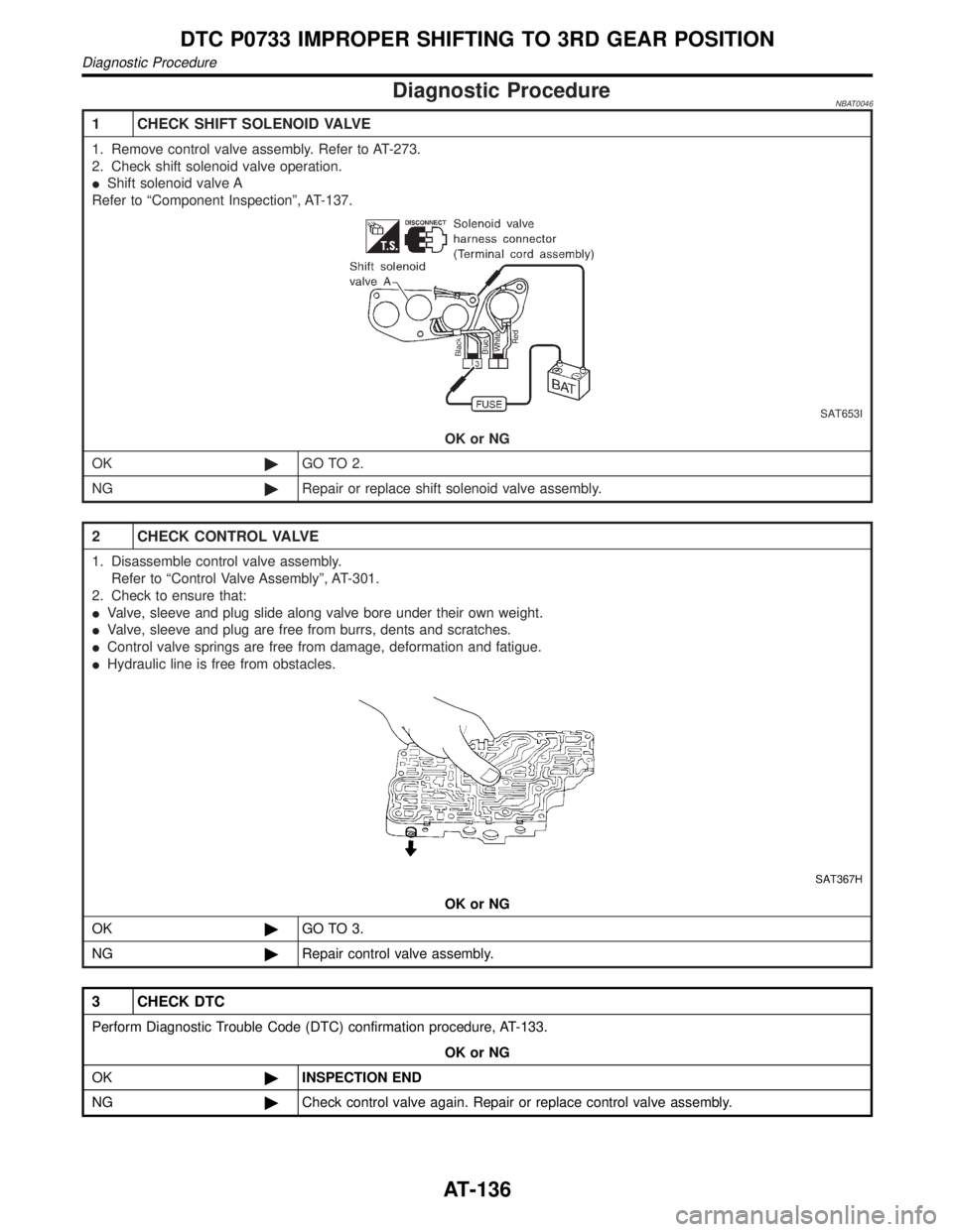
1 CHECK SHIFT SOLENOID VALVE
1. Remove control valve assembly. Refer to AT-273.
2. Check shift solenoid valve operation.
IShift solenoid valve A
Refer to ªComponent Inspectionº, AT-137.
SAT653I
OK or NG
OK©GO TO 2.
NG©Repair or replace shift solenoid valve assembly.
2 CHECK CONTROL VALVE
1. Disassemble control valve assembly.
Refer to ªControl Valve Assemblyº, AT-301.
2. Check to ensure that:
IValve, sleeve and plug slide along valve bore under their own weight.
IValve, sleeve and plug are free from burrs, dents and scratches.
IControl valve springs are free from damage, deformation and fatigue.
IHydraulic line is free from obstacles.
SAT367H
OK or NG
OK©GO TO 3.
NG©Repair control valve assembly.
3 CHECK DTC
Perform Diagnostic Trouble Code (DTC) confirmation procedure, AT-133.
OK or NG
OK©INSPECTION END
NG©Check control valve again. Repair or replace control valve assembly.
DTC P0733 IMPROPER SHIFTING TO 3RD GEAR POSITION
Diagnostic Procedure
AT-136
Page 149 of 2395
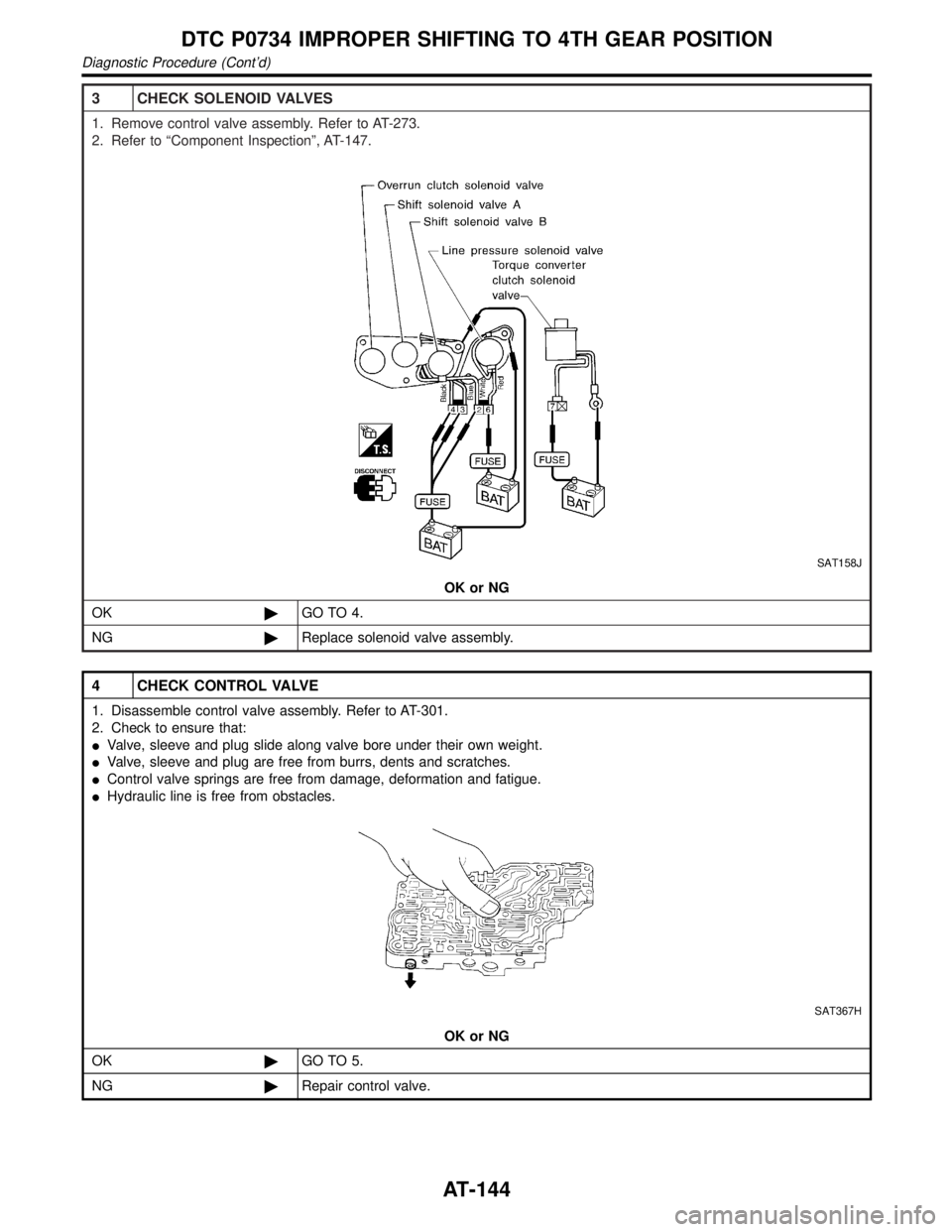
3 CHECK SOLENOID VALVES
1. Remove control valve assembly. Refer to AT-273.
2. Refer to ªComponent Inspectionº, AT-147.
SAT158J
OK or NG
OK©GO TO 4.
NG©Replace solenoid valve assembly.
4 CHECK CONTROL VALVE
1. Disassemble control valve assembly. Refer to AT-301.
2. Check to ensure that:
IValve, sleeve and plug slide along valve bore under their own weight.
IValve, sleeve and plug are free from burrs, dents and scratches.
IControl valve springs are free from damage, deformation and fatigue.
IHydraulic line is free from obstacles.
SAT367H
OK or NG
OK©GO TO 5.
NG©Repair control valve.
DTC P0734 IMPROPER SHIFTING TO 4TH GEAR POSITION
Diagnostic Procedure (Cont'd)
AT-144
Page 162 of 2395
Diagnostic Procedure=NBAT0055
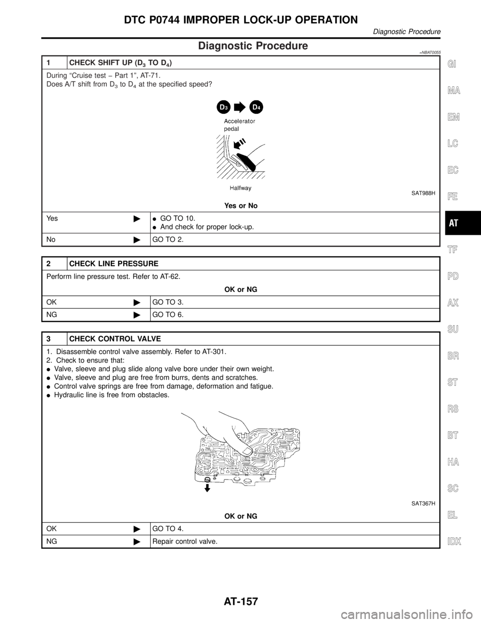
1 CHECK SHIFT UP (D3TO D4)
During ªCruise test þ Part 1º, AT-71.
Does A/T shift from D
3to D4at the specified speed?
SAT988H
YesorNo
Ye s©IGO TO 10.
IAnd check for proper lock-up.
No©GO TO 2.
2 CHECK LINE PRESSURE
Perform line pressure test. Refer to AT-62.
OK or NG
OK©GO TO 3.
NG©GO TO 6.
3 CHECK CONTROL VALVE
1. Disassemble control valve assembly. Refer to AT-301.
2. Check to ensure that:
IValve, sleeve and plug slide along valve bore under their own weight.
IValve, sleeve and plug are free from burrs, dents and scratches.
IControl valve springs are free from damage, deformation and fatigue.
IHydraulic line is free from obstacles.
SAT367H
OK or NG
OK©GO TO 4.
NG©Repair control valve.
GI
MA
EM
LC
EC
FE
TF
PD
AX
SU
BR
ST
RS
BT
HA
SC
EL
IDX
DTC P0744 IMPROPER LOCK-UP OPERATION
Diagnostic Procedure
AT-157
Page 423 of 2395
This component controls the hydraulic circuit and increases, holds
or decreases hydraulic pressure to all or individual wheels. The
ABS actuator and electric unit is serviced as an assembly.
ABS Actuator OperationNBBR0091S0301
Inlet solenoid
valveOutlet solenoid
valve
Normal brake operation OFF (Open) OFF (Closed)Master cylinder brake fluid pressure is directly
transmitted to caliper via the inlet solenoid valve.
ABS operationPressure hold ON (Closed) OFF (Closed)Hydraulic circuit is shut off to hold the caliper
brake fluid pressure.
Pressure
decreaseON (Closed) ON (Open)Caliper brake fluid is sent to reservoir via the out-
let solenoid valve. Then it is pushed up to the
master cylinder by pump.
Pressure increase OFF (Open) OFF (Closed)Master cylinder brake fluid pressure is transmitted
to caliper.
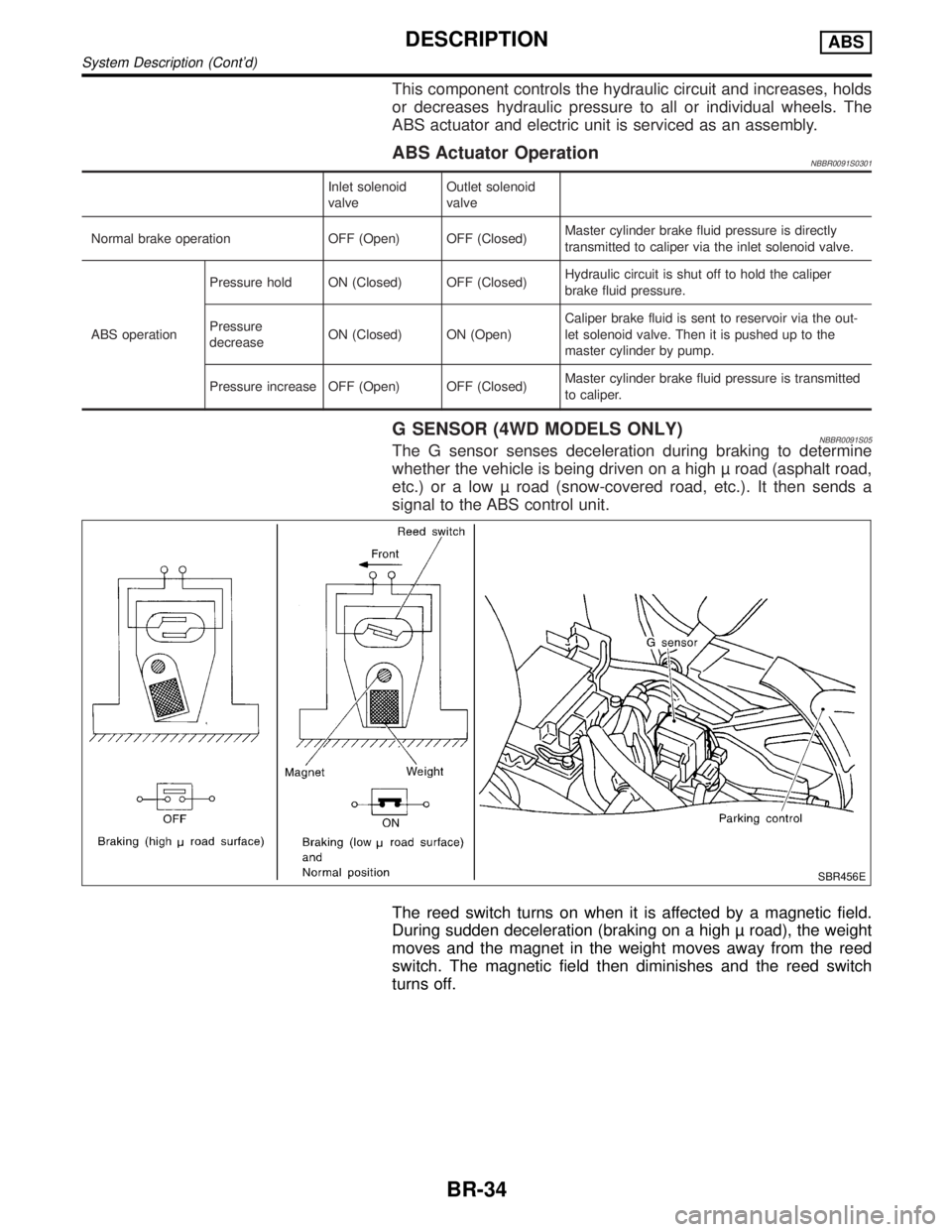
G SENSOR (4WD MODELS ONLY)NBBR0091S05The G sensor senses deceleration during braking to determine
whether the vehicle is being driven on a high road (asphalt road,
etc.) or a low road (snow-covered road, etc.). It then sends a
signal to the ABS control unit.
SBR456E
The reed switch turns on when it is affected by a magnetic field.
During sudden deceleration (braking on a high road), the weight
moves and the magnet in the weight moves away from the reed
switch. The magnetic field then diminishes and the reed switch
turns off.
DESCRIPTIONABS
System Description (Cont'd)
BR-34
Page 655 of 2395
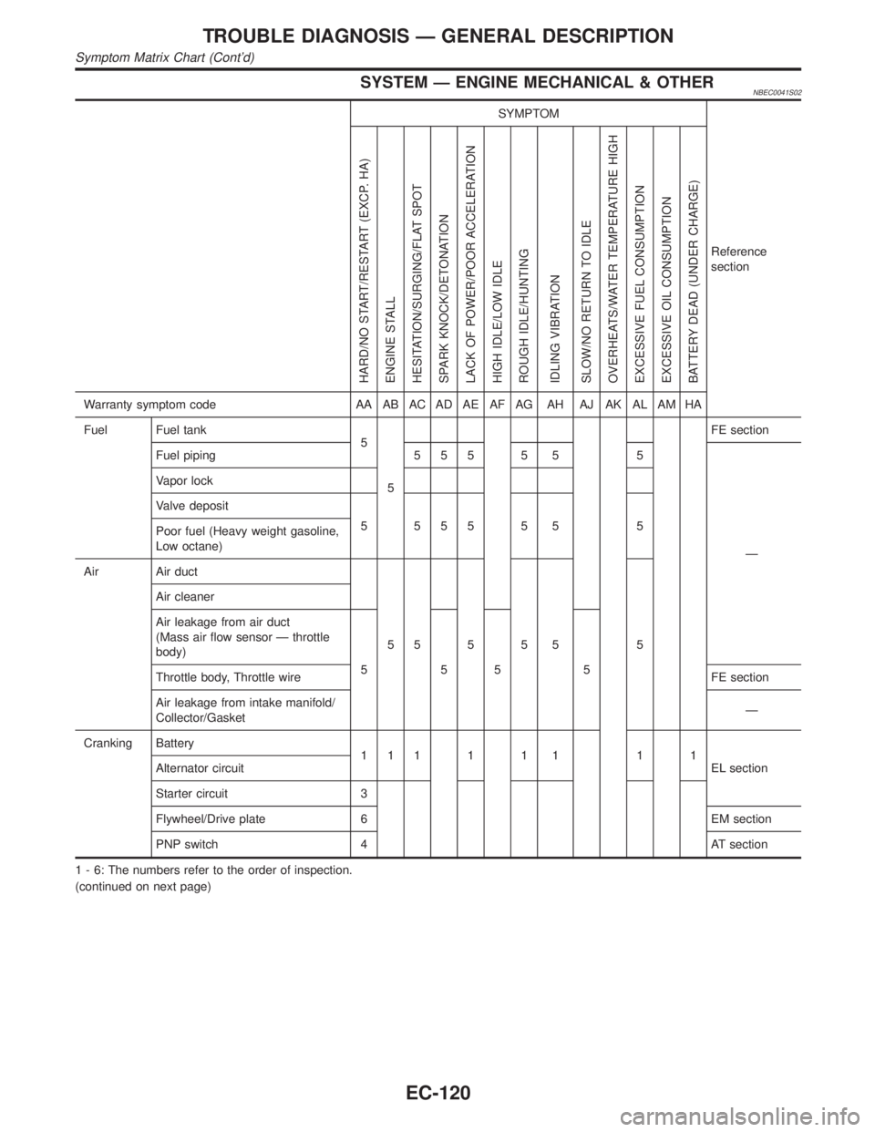
SYSTEM Ð ENGINE MECHANICAL & OTHERNBEC0041S02
SYMPTOM
Reference
section
HARD/NO START/RESTART (EXCP. HA)
ENGINE STALL
HESITATION/SURGING/FLAT SPOT
SPARK KNOCK/DETONATION
LACK OF POWER/POOR ACCELERATION
HIGH IDLE/LOW IDLE
ROUGH IDLE/HUNTING
IDLING VIBRATION
SLOW/NO RETURN TO IDLE
OVERHEATS/WATER TEMPERATURE HIGH
EXCESSIVE FUEL CONSUMPTION
EXCESSIVE OIL CONSUMPTION
BATTERY DEAD (UNDER CHARGE)
Warranty symptom code AA AB AC AD AE AF AG AH AJ AK AL AM HA
Fuel Fuel tank
5
5FE section
Fuel piping 5 5 5 5 5 5
Ð Vapor lock
Valve deposit
5 555 5 5 5
Poor fuel (Heavy weight gasoline,
Low octane)
Air Air duct
55555 5 Air cleaner
Air leakage from air duct
(Mass air flow sensor Ð throttle
body)
555 5
Throttle body, Throttle wireFE section
Air leakage from intake manifold/
Collector/GasketÐ
Cranking Battery
111111 11
EL section Alternator circuit
Starter circuit 3
Flywheel/Drive plate 6 EM section
PNP switch 4 AT section
1 - 6: The numbers refer to the order of inspection.
(continued on next page)
TROUBLE DIAGNOSIS Ð GENERAL DESCRIPTION
Symptom Matrix Chart (Cont'd)
EC-120
Page 896 of 2395
11 CHECK EVAP CANISTER
Weigh the EVAP canister with the EVAP canister vent control valve attached.
The weight should be less than 1.8 kg (4.0 lb).
OK or NG
OK (With CONSULT-II)©GO TO 13.
OK (Without CONSULT-
II)©GO TO 14.
NG©GO TO 12.
12 DETECT MALFUNCTIONING PART
Check the following.
IEVAP canister for damage
IEVAP hose between EVAP canister and water separator for clogging or poor connection
©Repair hose or replace EVAP canister.
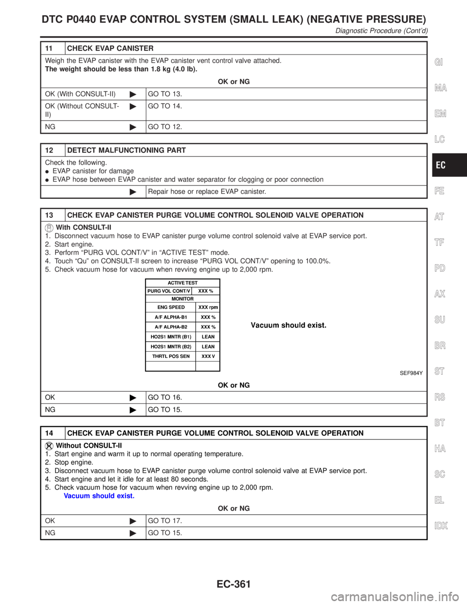
13 CHECK EVAP CANISTER PURGE VOLUME CONTROL SOLENOID VALVE OPERATION
With CONSULT-II
1. Disconnect vacuum hose to EVAP canister purge volume control solenoid valve at EVAP service port.
2. Start engine.
3. Perform ªPURG VOL CONT/Vº in ªACTIVE TESTº mode.
4. Touch ªQuº on CONSULT-II screen to increase ªPURG VOL CONT/Vº opening to 100.0%.
5. Check vacuum hose for vacuum when revving engine up to 2,000 rpm.
SEF984Y
OK or NG
OK©GO TO 16.
NG©GO TO 15.
14 CHECK EVAP CANISTER PURGE VOLUME CONTROL SOLENOID VALVE OPERATION
Without CONSULT-II
1. Start engine and warm it up to normal operating temperature.
2. Stop engine.
3. Disconnect vacuum hose to EVAP canister purge volume control solenoid valve at EVAP service port.
4. Start engine and let it idle for at least 80 seconds.
5. Check vacuum hose for vacuum when revving engine up to 2,000 rpm.
Vacuum should exist.
OK or NG
OK©GO TO 17.
NG©GO TO 15.
GI
MA
EM
LC
FE
AT
TF
PD
AX
SU
BR
ST
RS
BT
HA
SC
EL
IDX
DTC P0440 EVAP CONTROL SYSTEM (SMALL LEAK) (NEGATIVE PRESSURE)
Diagnostic Procedure (Cont'd)
EC-361