heater INFINITI QX4 2001 Factory Service Manual
[x] Cancel search | Manufacturer: INFINITI, Model Year: 2001, Model line: QX4, Model: INFINITI QX4 2001Pages: 2395, PDF Size: 43.2 MB
Page 5 of 2395

Attachment No.14
TID CID
P0420 01H 01H Max. X -
P0420 02H 81H Min. X -
P0430 03H 02H Max. X -
P0430 04H 82H Min. X -
P0440 05H 03H Max. X -
P1440
★1 05H 03H Max. X -
EVAP control system purge flow monitoring P1447 06H 83H Min. X mV
EVAP control system (Very small leak) P1441
★2 07H 03H Max. X -
P0133 09H 04H Max. X ms
P0131 0AH 84H Min. X mV
P0130 0BH 04H Max. X mV
P0132 0CH 04H Max. X mV
P0134 0DH 04H Max. X s
P0153 11H 05H Max. X ms
P0151 12H 85H Min. X mV
P0150 13H 05H Max. X mV
P0152 14H 05H Max. X mV
P0154 15H 05H Max. X s
P0139 19H 86H Min. X mV/500ms
P0137 1AH 86H Min. X mV
P0140 1BH 06H Max. X mV
P0138 1CH 06H Max. X mV
P0159 21H 87H Min. X mV/500ms
P0157 22H 87H Min. X mV
P0160 23H 07H Max. X mV
P0158 24H 07H Max. X mV
P0135 29H 08H Max. X mV
P0135 2AH 88H Min. X mV
P0155 2BH 09H Max. X mV
P0155 2CH 89H Min. X mV
P0141 2DH 0AH Max. X mV
P0141 2EH 8AH Min. X mV
P0161 2FH 0BH Max. X mV
P0161 30H 8BH Min. X mV
TEST VALUE AND TEST LIMIT (GST ONLY — NOT APPLICABLE TO CONSULT-II)
The following is the information specified in Mode 6 of SAE J1979.
The test value is a parameter used to determine whether a system/circuit diagnostic test is “OK” or “NG” while
being monitored by the ECM during self-diagnosis. The test limit is a reference value which is specified as the
maximum or minimum value and is compared with the test value being monitored.
Items for which these data (test value and test limit) are displayed are the same as SRT code items.
These data (test value and test limit) are specified by Test ID (TID) and Component ID (CID) and can be dis-
played on the GST screen.
: Applicable ・: Not applicable
SRT item Self-diagnostic test item DTCTest value
(GST display)Te s t limit Application Unit
CATALYSTThree way catalyst function (Bank 1)
Three way catalyst function (Bank 2)
EVAP SYSTEMEVAP control system (Small leak)
HO2SHeated oxygen sensor 1(Bank 1)
Heated oxygen sensor 1(Bank 2)
Heated oxygen sensor 2(Bank 1)
Heated oxygen sensor 2(Bank 2)
HO2S HTRHeated oxygen sensor 1 heater(Bank 1)
Heated oxygen sensor 2 heater(Bank 2)
Heated oxygen sensor 2 heater(Bank 1)
Heated oxygen sensor 2 heater(Bank 2)
★<021103d60225025802430245025002540200024d024f02440245024c0253020002240212021202000236022702130213022502000245024e02470249024e0245020c0200023702240212021202000236022702130213022502000245024e02470249024e02
45020c02000232021502100200023602310213021502240225> engine, JR50 VQ35DE engine 2001★<021203d60225025802430245025002540200024d024f02440245024c02530200022102130213020002360231021302100224022502000245024e02470249024e0245020c02000223022102130213020002360231021302100224022502000245024e024702
49024e024502000212021002100211022d0239020e>
Page 538 of 2395

CONSULT-II Reference Value in Data Monitor
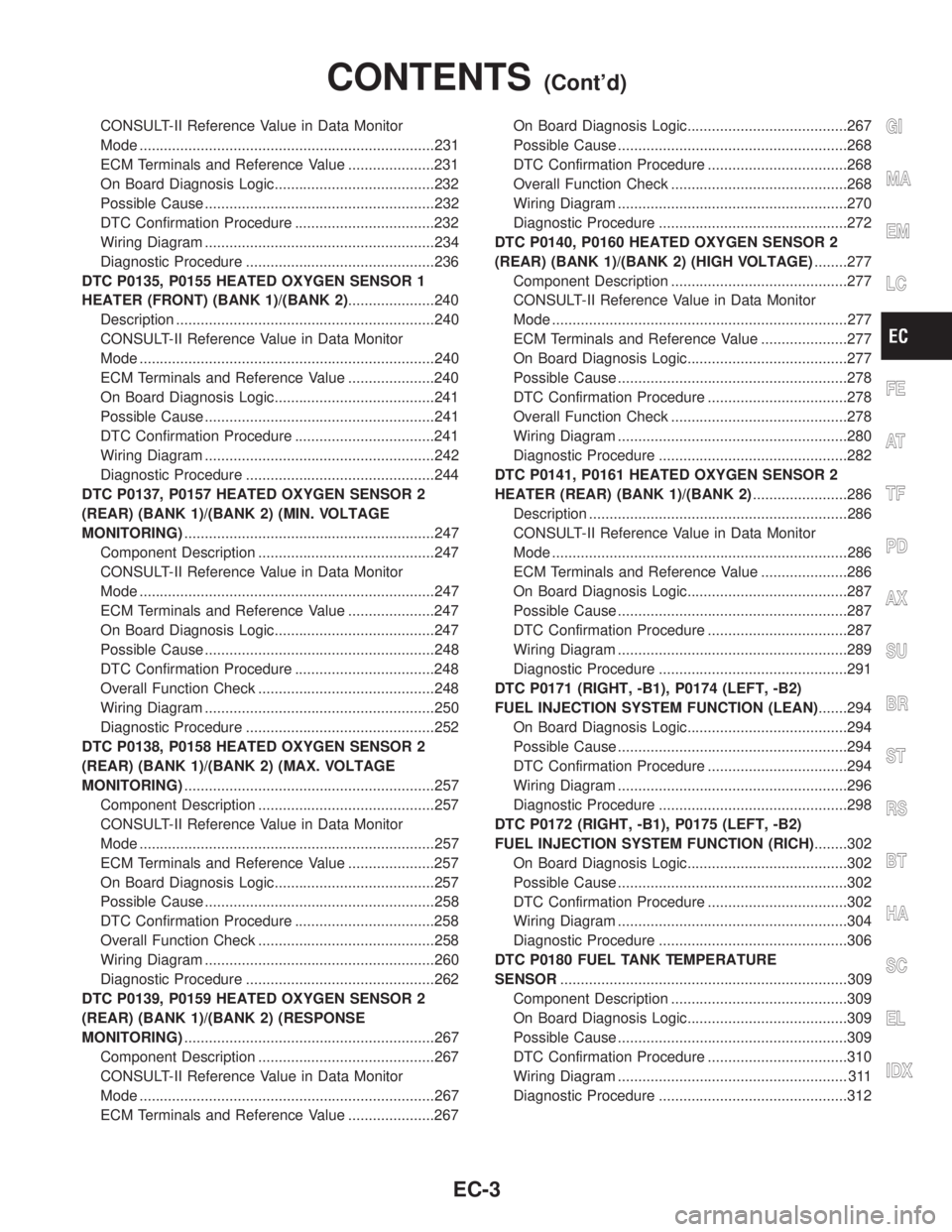
Mode ........................................................................231
ECM Terminals and Reference Value .....................231
On Board Diagnosis Logic.......................................232
Possible Cause ........................................................232
DTC Confirmation Procedure ..................................232
Wiring Diagram ........................................................234
Diagnostic Procedure ..............................................236
DTC P0135, P0155 HEATED OXYGEN SENSOR 1
HEATER (FRONT) (BANK 1)/(BANK 2).....................240
Description ...............................................................240
CONSULT-II Reference Value in Data Monitor
Mode ........................................................................240
ECM Terminals and Reference Value .....................240
On Board Diagnosis Logic.......................................241
Possible Cause ........................................................241
DTC Confirmation Procedure ..................................241
Wiring Diagram ........................................................242
Diagnostic Procedure ..............................................244
DTC P0137, P0157 HEATED OXYGEN SENSOR 2
(REAR) (BANK 1)/(BANK 2) (MIN. VOLTAGE
MONITORING).............................................................247
Component Description ...........................................247
CONSULT-II Reference Value in Data Monitor
Mode ........................................................................247
ECM Terminals and Reference Value .....................247
On Board Diagnosis Logic.......................................247
Possible Cause ........................................................248
DTC Confirmation Procedure ..................................248
Overall Function Check ...........................................248
Wiring Diagram ........................................................250
Diagnostic Procedure ..............................................252
DTC P0138, P0158 HEATED OXYGEN SENSOR 2
(REAR) (BANK 1)/(BANK 2) (MAX. VOLTAGE
MONITORING).............................................................257
Component Description ...........................................257
CONSULT-II Reference Value in Data Monitor
Mode ........................................................................257
ECM Terminals and Reference Value .....................257
On Board Diagnosis Logic.......................................257
Possible Cause ........................................................258
DTC Confirmation Procedure ..................................258
Overall Function Check ...........................................258
Wiring Diagram ........................................................260
Diagnostic Procedure ..............................................262
DTC P0139, P0159 HEATED OXYGEN SENSOR 2
(REAR) (BANK 1)/(BANK 2) (RESPONSE
MONITORING).............................................................267
Component Description ...........................................267
CONSULT-II Reference Value in Data Monitor
Mode ........................................................................267
ECM Terminals and Reference Value .....................267On Board Diagnosis Logic.......................................267
Possible Cause ........................................................268
DTC Confirmation Procedure ..................................268
Overall Function Check ...........................................268
Wiring Diagram ........................................................270
Diagnostic Procedure ..............................................272
DTC P0140, P0160 HEATED OXYGEN SENSOR 2
(REAR) (BANK 1)/(BANK 2) (HIGH VOLTAGE)........277
Component Description ...........................................277
CONSULT-II Reference Value in Data Monitor
Mode ........................................................................277
ECM Terminals and Reference Value .....................277
On Board Diagnosis Logic.......................................277
Possible Cause ........................................................278
DTC Confirmation Procedure ..................................278
Overall Function Check ...........................................278
Wiring Diagram ........................................................280
Diagnostic Procedure ..............................................282
DTC P0141, P0161 HEATED OXYGEN SENSOR 2
HEATER (REAR) (BANK 1)/(BANK 2).......................286
Description ...............................................................286
CONSULT-II Reference Value in Data Monitor
Mode ........................................................................286
ECM Terminals and Reference Value .....................286
On Board Diagnosis Logic.......................................287
Possible Cause ........................................................287
DTC Confirmation Procedure ..................................287
Wiring Diagram ........................................................289
Diagnostic Procedure ..............................................291
DTC P0171 (RIGHT, -B1), P0174 (LEFT, -B2)
FUEL INJECTION SYSTEM FUNCTION (LEAN).......294
On Board Diagnosis Logic.......................................294
Possible Cause ........................................................294
DTC Confirmation Procedure ..................................294
Wiring Diagram ........................................................296
Diagnostic Procedure ..............................................298
DTC P0172 (RIGHT, -B1), P0175 (LEFT, -B2)
FUEL INJECTION SYSTEM FUNCTION (RICH)........302
On Board Diagnosis Logic.......................................302
Possible Cause ........................................................302
DTC Confirmation Procedure ..................................302
Wiring Diagram ........................................................304
Diagnostic Procedure ..............................................306
DTC P0180 FUEL TANK TEMPERATURE
SENSOR......................................................................309
Component Description ...........................................309
On Board Diagnosis Logic.......................................309
Possible Cause ........................................................309
DTC Confirmation Procedure ..................................310
Wiring Diagram ........................................................ 311
Diagnostic Procedure ..............................................312GI
MA
EM
LC
FE
AT
TF
PD
AX
SU
BR
ST
RS
BT
HA
SC
EL
IDX
CONTENTS(Cont'd)
EC-3
Page 542 of 2395

CONSULT-II Reference Value in Data Monitor
Mode ........................................................................585
ECM Terminals and Reference Value .....................585
On Board Diagnosis Logic.......................................586
Possible Cause ........................................................586
DTC Confirmation Procedure ..................................586
Wiring Diagram ........................................................587
Diagnostic Procedure ..............................................588
DTC P1491 VACUUM CUT VALVE BYPASS
VALVE..........................................................................591
Description ...............................................................591
CONSULT-II Reference Value in Data Monitor
Mode ........................................................................591
ECM Terminals and Reference Value .....................591
On Board Diagnosis Logic.......................................592
Possible Cause ........................................................592
DTC Confirmation Procedure ..................................592
Overall Function Check ...........................................593
Wiring Diagram ........................................................594
Diagnostic Procedure ..............................................595
DTC P1605 A/T DIAGNOSIS COMMUNICATION
LINE.............................................................................603
Component Description ...........................................603
On Board Diagnosis Logic.......................................603
Possible Cause ........................................................603
DTC Confirmation Procedure ..................................603
DTC P1706 PARK/NEUTRAL POSITION (PNP)
SWITCH.......................................................................604
Component Description ...........................................604
CONSULT-II Reference Value in Data Monitor
Mode ........................................................................604
ECM Terminals and Reference Value .....................604
On Board Diagnosis Logic.......................................604
Possible Cause ........................................................604
DTC Confirmation Procedure ..................................605
Overall Function Check ...........................................606
Wiring Diagram ........................................................607
Diagnostic Procedure ..............................................608
VARIABLE INDUCTION AIR CONTROL SYSTEM
(VIAS)...........................................................................610
Description ...............................................................610
ECM Terminals and Reference Value ..................... 611
Wiring Diagram ........................................................612
Diagnostic Procedure ..............................................613
INJECTOR...................................................................616
Component Description ...........................................616
CONSULT-II Reference Value in Data Monitor
Mode ........................................................................616
ECM Terminals and Reference Value .....................616
Wiring Diagram ........................................................617Diagnostic Procedure ..............................................618
START SIGNAL...........................................................621
CONSULT-II Reference Value in Data Monitor
Mode ........................................................................621
ECM Terminals and Reference Value .....................621
Wiring Diagram ........................................................622
Diagnostic Procedure ..............................................623
FUEL PUMP.................................................................625
System Description ..................................................625
Component Description ...........................................625
CONSULT-II Reference Value in Data Monitor
Mode ........................................................................625
ECM Terminals and Reference Value .....................626
Wiring Diagram ........................................................627
Diagnostic Procedure ..............................................628
POWER STEERING OIL PRESSURE SWITCH.........634
Component Description ...........................................634
CONSULT-II Reference Value in Data Monitor
Mode ........................................................................634
ECM Terminals and Reference Value .....................634
Wiring Diagram ........................................................635
Diagnostic Procedure ..............................................636
REFRIGERANT PRESSURE SENSOR......................639
Description ...............................................................639
ECM Terminals and Reference Value .....................639
Wiring Diagram ........................................................640
Diagnostic Procedure ..............................................641
ELECTRICAL LOAD SIGNAL.....................................643
ECM Terminals and Reference Value .....................643
Wiring Diagram ........................................................644
Diagnostic Procedure ..............................................645
MIL & DATA LINK CONNECTORS............................648
Wiring Diagram ........................................................648
SERVICE DATA AND SPECIFICATIONS (SDS).......649
Fuel Pressure Regulator..........................................649
Idle Speed and Ignition Timing ................................649
Mass Air Flow Sensor..............................................649
Engine Coolant Temperature Sensor ......................649
Heated Oxygen Sensor 1 Heater (Front) ................649
Fuel Pump ...............................................................649
IACV-AAC Valve ......................................................649
Injector .....................................................................649
Resistor ....................................................................649
Throttle Position Sensor ..........................................650
Calculated Load Value.............................................650
Intake Air Temperature Sensor ................................650
Heated Oxygen Sensor 2 Heater (Rear).................650
Crankshaft Position Sensor (REF) ..........................650
Fuel Tank Temperature Sensor ...............................650
Camshaft Position Sensor (PHASE) .......................650GI
MA
EM
LC
FE
AT
TF
PD
AX
SU
BR
ST
RS
BT
HA
SC
EL
IDX
CONTENTS(Cont'd)
EC-7
Page 562 of 2395

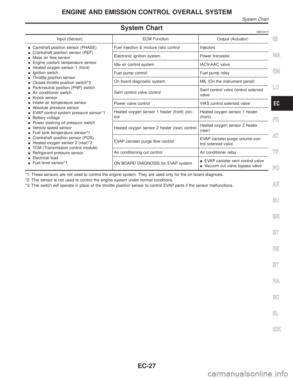
System ChartNBEC0013
Input (Sensor) ECM Function Output (Actuator)
ICamshaft position sensor (PHASE)
ICrankshaft position sensor (REF)
IMass air flow sensor
IEngine coolant temperature sensor
IHeated oxygen sensor 1 (front)
IIgnition switch
IThrottle position sensor
IClosed throttle position switch*3
IPark/neutral position (PNP) switch
IAir conditioner switch
IKnock sensor
IIntake air temperature sensor
IAbsolute pressure sensor
IEVAP control system pressure sensor*1
IBattery voltage
IPower steering oil pressure switch
IVehicle speed sensor
IFuel tank temperature sensor*1
ICrankshaft position sensor (POS)
IHeated oxygen sensor 2 (rear)*2
ITCM (Transmission control module)
IRefrigerant pressure sensor
IElectrical load
IFuel level sensor*1Fuel injection & mixture ratio control Injectors
Electronic ignition system Power transistor
Idle air control system IACV-AAC valve
Fuel pump control Fuel pump relay
On board diagnostic system MIL (On the instrument panel)
Swirl control valve controlSwirl control valve control solenoid
valve
Power valve control VIAS control solenoid valve
Heated oxygen sensor 1 heater (front) con-
trolHeated oxygen sensor 1 heater
(front)
Heated oxygen sensor 2 heater (rear) controlHeated oxygen sensor 2 heater
(rear)
EVAP canister purge flow controlEVAP canister purge volume con-
trol solenoid valve
Air conditioning cut control Air conditioner relay
ON BOARD DIAGNOSIS for EVAP systemIEVAP canister vent control valve
IVacuum cut valve bypass valve
*1: These sensors are not used to control the engine system. They are used only for the on board diagnosis.
*2: This sensor is not used to control the engine system under normal conditions.
*3: This switch will operate in place of the throttle position sensor to control EVAP parts if the sensor malfunctions.GI
MA
EM
LC
FE
AT
TF
PD
AX
SU
BR
ST
RS
BT
HA
SC
EL
IDX
ENGINE AND EMISSION CONTROL OVERALL SYSTEM
System Chart
EC-27
Page 579 of 2395

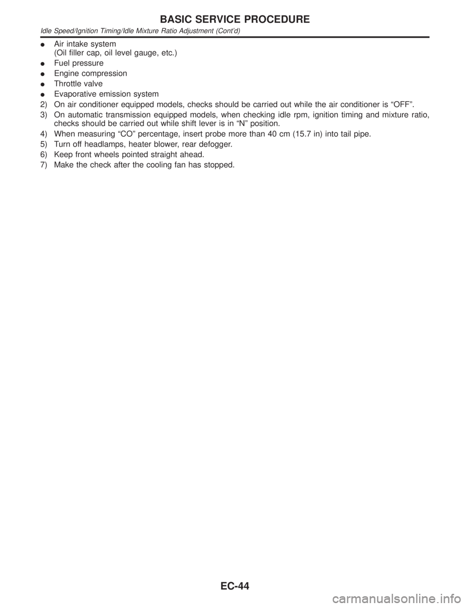
IAir intake system
(Oil filler cap, oil level gauge, etc.)
IFuel pressure
IEngine compression
IThrottle valve
IEvaporative emission system
2) On air conditioner equipped models, checks should be carried out while the air conditioner is ªOFFº.
3) On automatic transmission equipped models, when checking idle rpm, ignition timing and mixture ratio,
checks should be carried out while shift lever is in ªNº position.
4) When measuring ªCOº percentage, insert probe more than 40 cm (15.7 in) into tail pipe.
5) Turn off headlamps, heater blower, rear defogger.
6) Keep front wheels pointed straight ahead.
7) Make the check after the cooling fan has stopped.
BASIC SERVICE PROCEDURE
Idle Speed/Ignition Timing/Idle Mixture Ratio Adjustment (Cont'd)
EC-44
Page 597 of 2395

SRT Item=NBEC0031S0310The table below shows required self-diagnostic items to set the SRT to ªCMPLTº.
SRT item
(CONSULT-II indica-
tion)Perfor-
mance Pri-
ority*Required self-diagnostic items to set the SRT to ªCMPLTºCorresponding
DTC No.
CATALYST 3 Three way catalyst function P0420, P0430
EVAP SYSTEM 2 EVAP control system (small leak) (negative pressure) P0440
3 EVAP control system (very small leak) (negative pressure)/
(positive pressure)P1441
3 EVAP control system purge flow monitoring P1447
O2 SENSOR 3 Heated oxygen sensor 1 (front) (circuit) P0130, P0150
Heated oxygen sensor 1 (front) (lean shift monitoring) P0131, P0151
Heated oxygen sensor 1 (front) (rich shift monitoring) P0132, P0152
Heated oxygen sensor 1 (front) (response monitoring) P0133, P0153
Heated oxygen sensor 1 (front) (high voltage) P0134, P0154
Heated oxygen sensor 2 (rear) (min. voltage monitoring) P0137, P0157
Heated oxygen sensor 2 (rear) (max. voltage monitoring) P0138, P0158
Heated oxygen sensor 2 (rear) (response monitoring) P0139, P0159
Heated oxygen sensor 2 (rear) (high voltage) P0140, P0160
O2 SEN HEATER 3 Heated oxygen sensor 1 heater (front) P0135, P0155
Heated oxygen sensor 2 heater (rear) P0141, P0161
*: If completion of several SRTs is required, perform driving patterns (DTC confirmation procedure), one by one based on the priority
for models with CONSULT-II.
ON BOARD DIAGNOSTIC SYSTEM DESCRIPTION
Emission-related Diagnostic Information (Cont'd)
EC-62
Page 604 of 2395

SRT item Self-diagnostic test itemTest value (GST display)
Test limit Application
TID CID
O2 SENSORHeated oxygen sensor 1 (front)
(bank 1)09H 04H Max. X
0AH 84H Min. X
0BH 04H Max. X
0CH 04H Max. X
0DH 04H Max. X
Heated oxygen sensor 1 (front)
(bank 2)11H 05H Max. X
12H 85H Min. X
13H 05H Max. X
14H 05H Max. X
15H 05H Max. X
Heated oxygen sensor 2 (rear)
(bank 1)19H 86H Min. X
1AH 86H Min. X
1BH 06H Max. X
1CH 06H Max. X
Heated oxygen sensor 2 (rear)
(bank 2)21H 87H Min. X
22H 87H Min. X
23H 07H Max. X
24H 07H Max. X
O2 SENSOR HEATERHeated oxygen sensor 1 (front) heater
(bank 1)29H 08H Max. X
2AH 88H Min. X
Heated oxygen sensor 1 (front) heater
(bank 2)2BH 09H Max. X
2CH 89H Min. X
Heated oxygen sensor 2 (rear) heater
(bank 1)2DH 0AH Max. X
2EH 8AH Min. X
Heated oxygen sensor 2 (rear) heater
(bank 2)2FH 0BH Max. X
30H 8BH Min. X
EMISSION-RELATED DIAGNOSTIC INFORMATION ITEMSNBEC0031S05X: Applicable Ð: Not applicable
Items
(CONSULT-II screen terms)DTC*1 SRT codeTest value/ Test
limit
(GST only)1st trip DTC*1 Reference page
NO DTC IS DETECTED.
FURTHER TESTING
MAY BE REQUIRED.P0000ÐÐÐÐ
MAF SEN/CIRCUIT P0100 Ð Ð X EC-150
ABSL PRES SEN/CIRC P0105 Ð Ð X EC-158
AIR TEMP SEN/CIRC P0110 Ð Ð X EC-164
COOLANT T SEN/CIRC P0115 Ð Ð X EC-169
GI
MA
EM
LC
FE
AT
TF
PD
AX
SU
BR
ST
RS
BT
HA
SC
EL
IDX
ON BOARD DIAGNOSTIC SYSTEM DESCRIPTION
Emission-related Diagnostic Information (Cont'd)
EC-69
Page 618 of 2395

ItemDIAGNOSTIC TEST MODE
WORK
SUP-
PORTSELF-DIAGNOSTIC
RESULTS
D ATA
MONI-
TORD ATA
MONI-
TOR
(SPEC)ACTIVE
TESTDTC & SRT
CONFIRMATION
DTC*1FREEZE
FRAME
DATA*2SRT
STATUSDTC
WORK
SUP-
PORT
ENGINE CONTROL COMPONENT PARTS
OUTPUT
Injectors X X X
Power transistor (Ignition timing)X
(Ignition
signal)XXX
IACV-AAC valve X X X X
EVAP canister purge volume
control solenoid valveX XXX X
Air conditioner relay X X
Fuel pump relay X X X X
Heated oxygen sensor 1 (front)
heaterXXXX
Heated oxygen sensor 2 (rear)
heaterXXXX
EVAP canister vent control valve X X X X
Vacuum cut valve bypass valve X X X X X
Swirl control valve control sole-
noid valveX XXX
VIAS control solenoid valve X X X
Intake valve timing control sole-
noid valveX XXX
Calculated load value X X X
X: Applicable
*1: This item includes 1st trip DTCs.
*2: This mode includes 1st trip freeze frame data or freeze frame data. The items appear on CONSULT-II screen in freeze frame data
mode only if a 1st trip DTC or DTC is detected. For details, refer to EC-60.
GI
MA
EM
LC
FE
AT
TF
PD
AX
SU
BR
ST
RS
BT
HA
SC
EL
IDX
ON BOARD DIAGNOSTIC SYSTEM DESCRIPTION
CONSULT-II (Cont'd)
EC-83
Page 624 of 2395
![INFINITI QX4 2001 Factory Service Manual Monitored item [Unit]ECM
input
signalsMain
signalsDescription Remarks
IGN TIMING [BTDC]qIIndicates the ignition timing computed
by ECM according to the input signals.IWhen the engine is stopped, a cer INFINITI QX4 2001 Factory Service Manual Monitored item [Unit]ECM
input
signalsMain
signalsDescription Remarks
IGN TIMING [BTDC]qIIndicates the ignition timing computed
by ECM according to the input signals.IWhen the engine is stopped, a cer](/img/42/57027/w960_57027-623.png)
Monitored item [Unit]ECM
input
signalsMain
signalsDescription Remarks
IGN TIMING [BTDC]qIIndicates the ignition timing computed
by ECM according to the input signals.IWhen the engine is stopped, a certain
value is indicated.
IACV-AAC/V [step]qIIndicates the IACV-AAC valve control
value computed by ECM according to
the input signals.
PURG VOL C/V [%]IIndicates the EVAP canister purge vol-
ume control solenoid valve control
value computed by the ECM according
to the input signals.
IThe opening becomes larger as the
value increases.
A/F ALPHA-B1 [%]q
IThe mean value of the air-fuel ratio
feedback correction factor per cycle is
indicated.IWhen the engine is stopped, a certain
value is indicated.
IThis data also includes the data for the
air-fuel ratio learning control. A/F ALPHA-B2 [%]q
AIR COND RLY
[ON/OFF]qIThe air conditioner relay control condi-
tion (determined by ECM according to
the input signal) is indicated.
FUEL PUMP RLY
[ON/OFF]qIIndicates the fuel pump relay control
condition determined by ECM accord-
ing to the input signals.
VENT CONT/V
[ON/OFF]IThe control condition of the EVAP can-
ister vent control valve (determined by
ECM according to the input signal) is
indicated.
ION ... Closed
OFF ... Open
HO2S1 HTR (B1)
[ON/OFF]IIndicates [ON/OFF] condition of front
heated oxygen sensor heater deter-
mined by ECM according to the input
signals. HO2S1 HTR (B2)
[ON/OFF]
HO2S2 HTR (B1)
[ON/OFF]IIndicates [ON/OFF] condition of rear
heated oxygen sensor heater deter-
mined by ECM according to the input
signals. HO2S2 HTR (B2)
[ON/OFF]
VC/V BYPASS/V
[ON/OFF]IThe control condition of the vacuum cut
valve bypass valve (determined by
ECM according to the input signal) is
indicated.
ION ... Open
OFF ... Closed
CAL/LD VALUE [%]IªCalculated load valueº indicates the
value of the current airflow divided by
peak airflow.
ABSOL TH´P/S [%]IªAbsolute throttle position sensorº indi-
cates the throttle opening computed by
ECM according to the signal voltage of
the throttle position sensor.
MASS AIRFLOW
[g´m/s]IIndicates the mass airflow computed by
ECM according to the signal voltage of
the mass airflow sensor.GI
MA
EM
LC
FE
AT
TF
PD
AX
SU
BR
ST
RS
BT
HA
SC
EL
IDX
ON BOARD DIAGNOSTIC SYSTEM DESCRIPTION
CONSULT-II (Cont'd)
EC-89
Page 651 of 2395

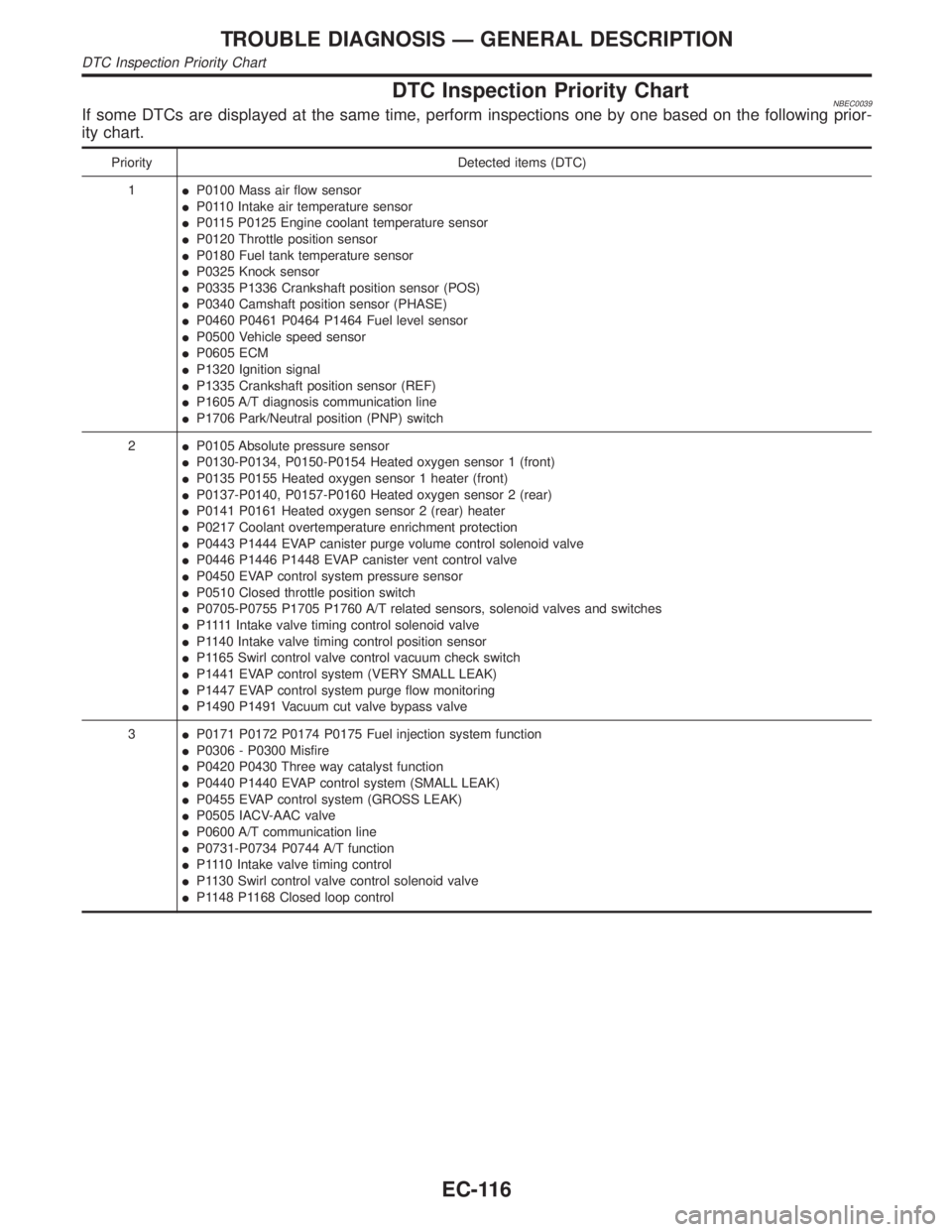
DTC Inspection Priority ChartNBEC0039If some DTCs are displayed at the same time, perform inspections one by one based on the following prior-
ity chart.
Priority Detected items (DTC)
1IP0100 Mass air flow sensor
IP0110 Intake air temperature sensor
IP0115 P0125 Engine coolant temperature sensor
IP0120 Throttle position sensor
IP0180 Fuel tank temperature sensor
IP0325 Knock sensor
IP0335 P1336 Crankshaft position sensor (POS)
IP0340 Camshaft position sensor (PHASE)
IP0460 P0461 P0464 P1464 Fuel level sensor
IP0500 Vehicle speed sensor
IP0605 ECM
IP1320 Ignition signal
IP1335 Crankshaft position sensor (REF)
IP1605 A/T diagnosis communication line
IP1706 Park/Neutral position (PNP) switch
2IP0105 Absolute pressure sensor
IP0130-P0134, P0150-P0154 Heated oxygen sensor 1 (front)
IP0135 P0155 Heated oxygen sensor 1 heater (front)
IP0137-P0140, P0157-P0160 Heated oxygen sensor 2 (rear)
IP0141 P0161 Heated oxygen sensor 2 (rear) heater
IP0217 Coolant overtemperature enrichment protection
IP0443 P1444 EVAP canister purge volume control solenoid valve
IP0446 P1446 P1448 EVAP canister vent control valve
IP0450 EVAP control system pressure sensor
IP0510 Closed throttle position switch
IP0705-P0755 P1705 P1760 A/T related sensors, solenoid valves and switches
IP 1111Intake valve timing control solenoid valve
IP1140 Intake valve timing control position sensor
IP1165 Swirl control valve control vacuum check switch
IP1441 EVAP control system (VERY SMALL LEAK)
IP1447 EVAP control system purge flow monitoring
IP1490 P1491 Vacuum cut valve bypass valve
3IP0171 P0172 P0174 P0175 Fuel injection system function
IP0306 - P0300 Misfire
IP0420 P0430 Three way catalyst function
IP0440 P1440 EVAP control system (SMALL LEAK)
IP0455 EVAP control system (GROSS LEAK)
IP0505 IACV-AAC valve
IP0600 A/T communication line
IP0731-P0734 P0744 A/T function
IP1110 Intake valve timing control
IP1130 Swirl control valve control solenoid valve
IP1148 P1168 Closed loop control
TROUBLE DIAGNOSIS Ð GENERAL DESCRIPTION
DTC Inspection Priority Chart
EC-116