INFINITI QX4 2005 Factory Manual Online
QX4 2005
INFINITI
INFINITI
https://www.carmanualsonline.info/img/42/57035/w960_57035-0.png
INFINITI QX4 2005 Factory Manual Online
Page 1305 of 3419
EC-114Revision: October 2005
TROUBLE DIAGNOSIS
2005 QX56
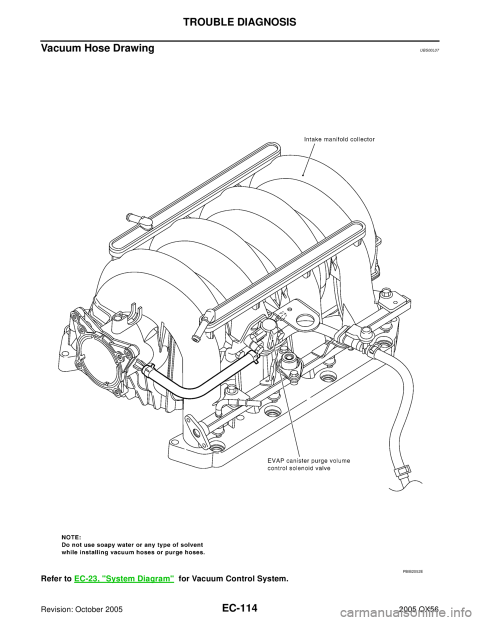
Vacuum Hose DrawingUBS00L07
Refer to EC-23, "System Diagram" for Vacuum Control System.
PBIB2052E
Page 1306 of 3419
TROUBLE DIAGNOSIS
EC-115
C
D
E
F
G
H
I
J
K
L
MA
EC
Revision: October 20052005 QX56
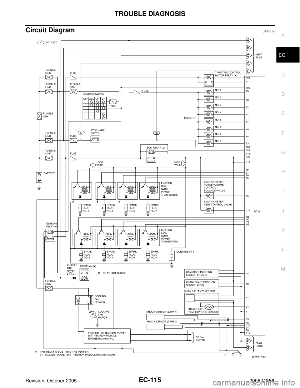
Circuit DiagramUBS00L08
BBWA1788E
Page 1348 of 3419
POWER SUPPLY AND GROUND CIRCUIT
EC-157
C
D
E
F
G
H
I
J
K
L
MA
EC
Revision: October 20052005 QX56
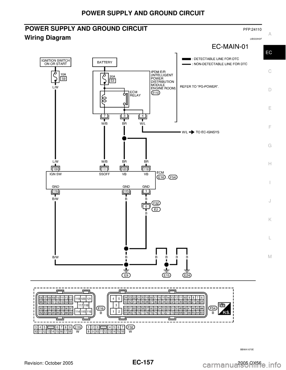
POWER SUPPLY AND GROUND CIRCUITPFP:24110
Wiring DiagramUBS00H0F
BBWA1670E
Page 1350 of 3419
POWER SUPPLY AND GROUND CIRCUIT
EC-159
C
D
E
F
G
H
I
J
K
L
MA
EC
Revision: October 20052005 QX56
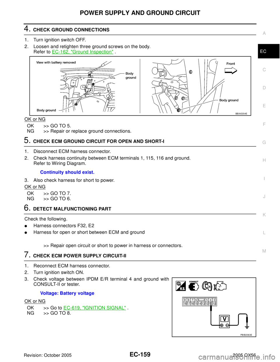
4. CHECK GROUND CONNECTIONS
1. Turn ignition switch OFF.
2. Loosen and retighten three ground screws on the body.
Refer to EC-162, "
Ground Inspection" .
OK or NG
OK >> GO TO 5.
NG >> Repair or replace ground connections.
5. CHECK ECM GROUND CIRCUIT FOR OPEN AND SHORT-I
1. Disconnect ECM harness connector.
2. Check harness continuity between ECM terminals 1, 115, 116 and ground.
Refer to Wiring Diagram.
3. Also check harness for short to power.
OK or NG
OK >> GO TO 7.
NG >> GO TO 6.
6. DETECT MALFUNCTIONING PART
Check the following.
�Harness connectors F32, E2
�Harness for open or short between ECM and ground
>> Repair open circuit or short to power in harness or connectors.
7. CHECK ECM POWER SUPPLY CIRCUIT-II
1. Reconnect ECM harness connector.
2. Turn ignition switch ON.
3. Check voltage between IPDM E/R terminal 4 and ground with
CONSULT-II or tester.
OK or NG
OK >> Go to EC-619, "IGNITION SIGNAL" .
NG >> GO TO 8.
BBIA0354E
Continuity should exist.
Voltage: Battery voltage
PBIB2063E
Page 1351 of 3419
EC-160Revision: October 2005
POWER SUPPLY AND GROUND CIRCUIT
2005 QX56
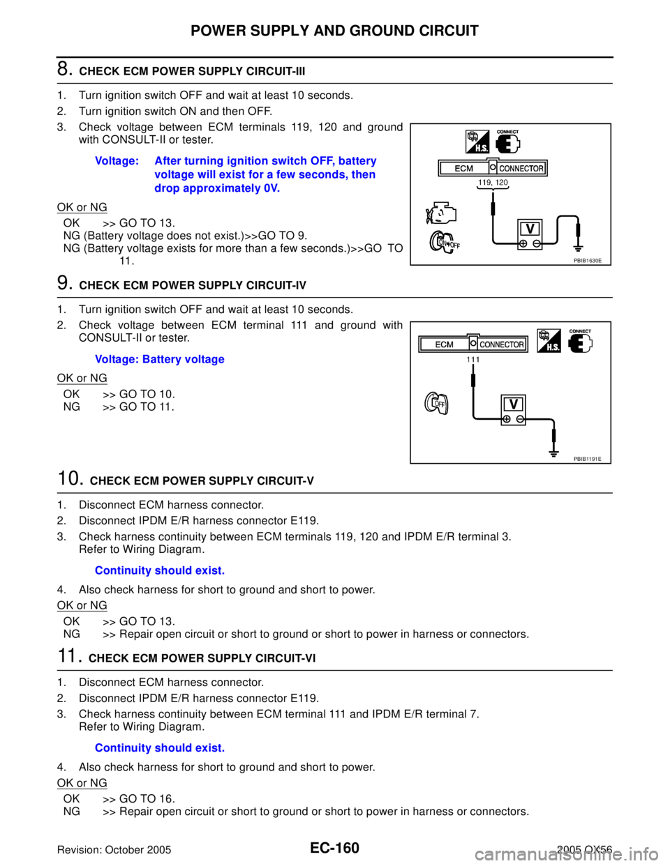
8. CHECK ECM POWER SUPPLY CIRCUIT-III
1. Turn ignition switch OFF and wait at least 10 seconds.
2. Turn ignition switch ON and then OFF.
3. Check voltage between ECM terminals 119, 120 and ground
with CONSULT-II or tester.
OK or NG
OK >> GO TO 13.
NG (Battery voltage does not exist.)>>GO TO 9.
NG (Battery voltage exists for more than a few seconds.)>>GO TO
11 .
9. CHECK ECM POWER SUPPLY CIRCUIT-IV
1. Turn ignition switch OFF and wait at least 10 seconds.
2. Check voltage between ECM terminal 111 and ground with
CONSULT-II or tester.
OK or NG
OK >> GO TO 10.
NG >> GO TO 11.
10. CHECK ECM POWER SUPPLY CIRCUIT-V
1. Disconnect ECM harness connector.
2. Disconnect IPDM E/R harness connector E119.
3. Check harness continuity between ECM terminals 119, 120 and IPDM E/R terminal 3.
Refer to Wiring Diagram.
4. Also check harness for short to ground and short to power.
OK or NG
OK >> GO TO 13.
NG >> Repair open circuit or short to ground or short to power in harness or connectors.
11 . CHECK ECM POWER SUPPLY CIRCUIT-VI
1. Disconnect ECM harness connector.
2. Disconnect IPDM E/R harness connector E119.
3. Check harness continuity between ECM terminal 111 and IPDM E/R terminal 7.
Refer to Wiring Diagram.
4. Also check harness for short to ground and short to power.
OK or NG
OK >> GO TO 16.
NG >> Repair open circuit or short to ground or short to power in harness or connectors.Voltage: After turning ignition switch OFF, battery
voltage will exist for a few seconds, then
drop approximately 0V.
PBIB1630E
Voltage: Battery voltage
PBIB11 91 E
Continuity should exist.
Continuity should exist.
Page 1352 of 3419

POWER SUPPLY AND GROUND CIRCUIT
EC-161
C
D
E
F
G
H
I
J
K
L
MA
EC
Revision: October 20052005 QX56
12. CHECK 20A FUSE
1. Disconnect 20A fuse from IPDM E/R.
2. Check 20A fuse.
OK or NG
OK >> GO TO 16.
NG >> Replace 20A fuse.
13. CHECK GROUND CONNECTIONS
1. Turn ignition switch OFF.
2. Loosen and retighten ground three screws on the body.
Refer to EC-162, "
Ground Inspection" .
OK or NG
OK >> GO TO 14.
NG >> Repair or replace ground connections.
14. CHECK ECM GROUND CIRCUIT FOR OPEN AND SHORT-II
1. Disconnect ECM harness connector.
2. Check harness continuity between ECM terminals 1, 115, 116 and ground.
Refer to Wiring Diagram.
3. Also check harness for short to power.
OK or NG
OK >> GO TO 16.
NG >> GO TO 15.
15. DETECT MALFUNCTIONING PART
Check the following.
�Harness connectors F32, E2
�Harness for open or short between ECM and ground
>> Repair open circuit or short to power in harness or connectors.
16. CHECK INTERMITTENT INCIDENT
Refer to EC-156, "
TROUBLE DIAGNOSIS FOR INTERMITTENT INCIDENT" .
OK or NG
OK >> Replace IPDM E/R.
NG >> Repair open circuit or short to power in harness or connectors.
BBIA0354E
Continuity should exist.
Page 1355 of 3419
EC-164Revision: October 2005
DTC U1000, U1001 CAN COMMUNICATION LINE
2005 QX56
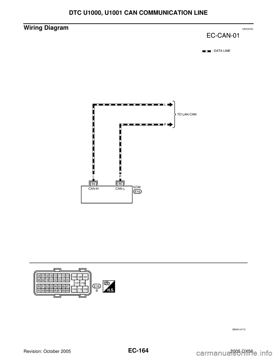
Wiring DiagramUBS00H0L
BBWA1671E
Page 1359 of 3419
EC-168Revision: October 2005
DTC P0037, P0038, P0057, P0058 HO2S2 HEATER
2005 QX56
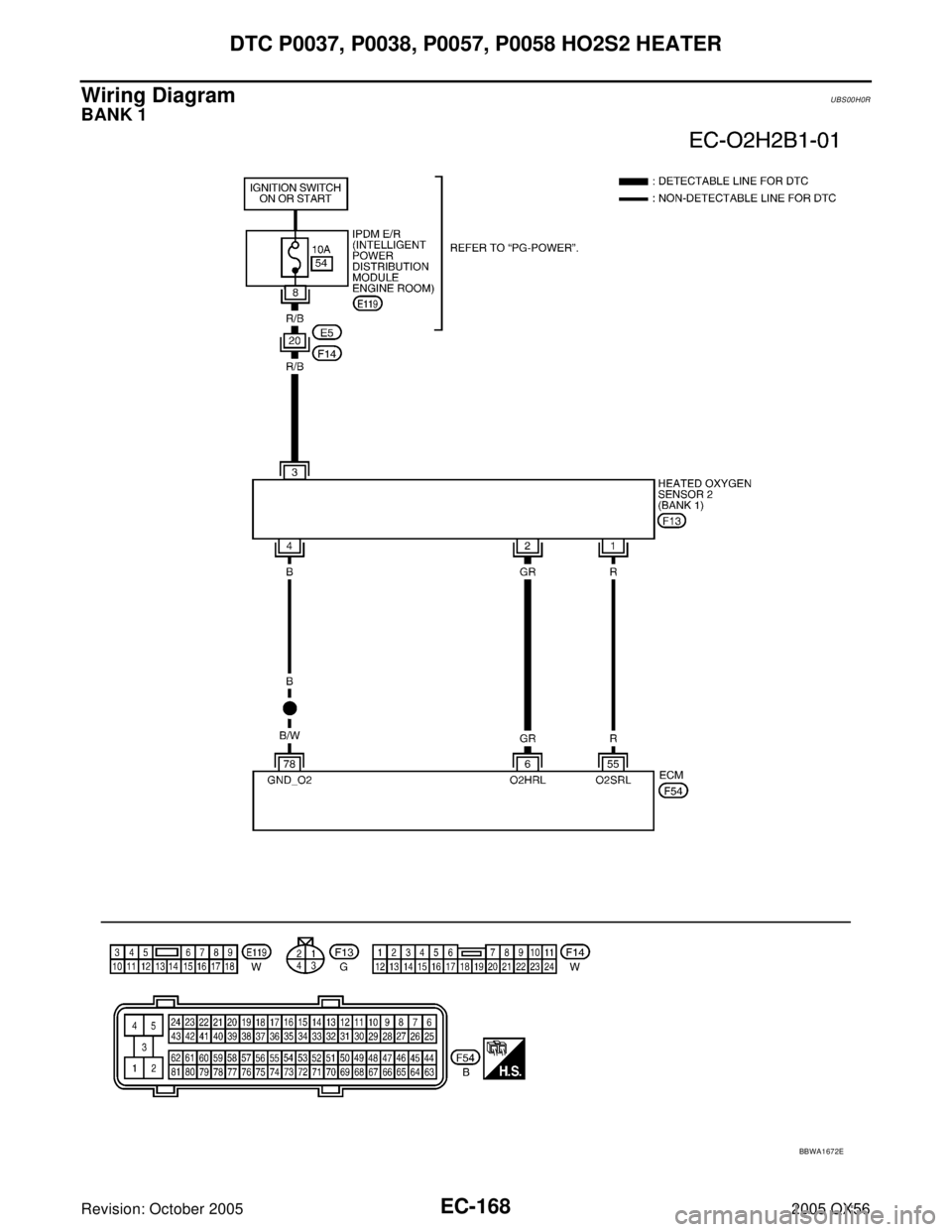
Wiring DiagramUBS00H0R
BANK 1
BBWA1672E
Page 1363 of 3419

EC-172Revision: October 2005
DTC P0037, P0038, P0057, P0058 HO2S2 HEATER
2005 QX56
2. CHECK HO2S2 POWER SUPPLY CIRCUIT
1. Disconnect heated oxygen sensor 2 harness connector.
2. Turn ignition switch ON.
3. Check voltage between HO2S2 terminal 3 and ground with
CONSULT-II or tester.
OK or NG
OK >> GO TO 4.
NG >> GO TO 3.
3. DETECT MALFUNCTIONING PART
Check the following.
�Harness connectors E5, F14
�IPDM E/R connector E119
�10A fuse
�Harness for open or short between heated oxygen sensor 2 and fuse
>> Repair harness or connectors.
4. CHECK HO2S2 OUTPUT SIGNAL CIRCUIT FOR OPEN AND SHORT
1. Turn ignition switch OFF.
2. Disconnect ECM harness connector.
3. Check harness continuity between ECM terminal and HO2S2 terminal as follows.
Refer to Wiring Diagram.
4. Also check harness for short to ground and short to power.
OK or NG
OK >> GO TO 5.
NG >> Repair open circuit or short to ground or short to power in harness or connectors.
BBIA0435E
Voltage: Battery voltage
PBIB0 112 E
DTCTe r m i n a l s
Bank
ECM Sensor
P0037, P0038 6 2 1
P0057, P0058 25 2 2
Continuity should exist.
Page 1368 of 3419
DTC P0101 MAF SENSOR
EC-177
C
D
E
F
G
H
I
J
K
L
MA
EC
Revision: October 20052005 QX56
Wiring DiagramUBS00H10
BBWA1674E
