audio visual INFINITI QX4 2005 Factory Service Manual
[x] Cancel search | Manufacturer: INFINITI, Model Year: 2005, Model line: QX4, Model: INFINITI QX4 2005Pages: 3419, PDF Size: 80.18 MB
Page 1 of 3419

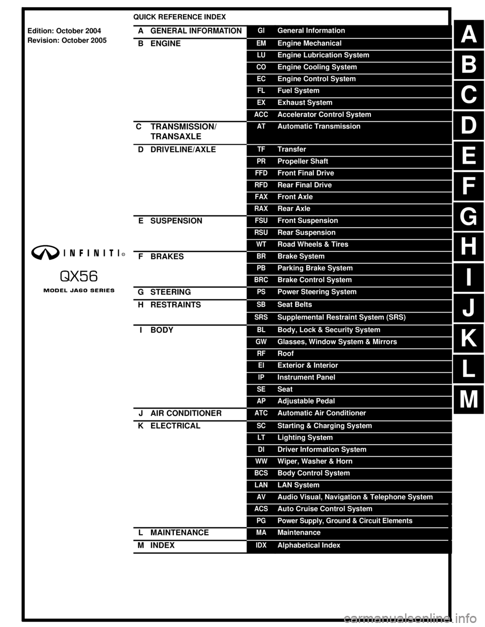
-1QUICK REFERENCE INDEX AGENERAL INFORMATIONGIGeneral InformationBENGINEEMEngine MechanicalLUEngine Lubrication SystemCOEngine Cooling SystemECEngine Control SystemFLFuel SystemEXExhaust SystemACCAccelerator Control SystemCTRANSMISSION/
TRANSAXLEATAutomatic TransmissionDDRIVELINE/AXLETFTransferPRPropeller ShaftFFDFront Final DriveRFDRear Final DriveFAXFront AxleRAXRear AxleESUSPENSIONFSUFront SuspensionRSURear SuspensionWTRoad Wheels & TiresFBRAKESBRBrake SystemPBParking Brake SystemBRCBrake Control SystemGSTEERINGPSPower Steering SystemHRESTRAINTSSBSeat BeltsSRSSupplemental Restraint System (SRS)IBODYBLBody, Lock & Security SystemGWGlasses, Window System & MirrorsRFRoofEIExterior & InteriorIPInstrument PanelSESeatAPAdjustable PedalJAIR CONDITIONERATCAutomatic Air ConditionerKELECTRICALSCStarting & Charging SystemLTLighting SystemDIDriver Information SystemWWWiper, Washer & HornBCSBody Control SystemLANLAN SystemAVAudio Visual, Navigation & Telephone SystemACSAuto Cruise Control SystemPGPower Supply, Ground & Circuit ElementsLMAINTENANCEMAMaintenanceMINDEXIDXAlphabetical IndexEdition: October 2004
Revision: October 2005BDACEFGHIJKLM
Page 590 of 3419

AV-1
AUDIO, VISUAL, NAVIGATION & TELEPHONE SYS-
TEM
K ELECTRICAL
CONTENTS
C
D
E
F
G
H
I
J
L
M
SECTION AV
A
B
AV
Revision: October 20052005 QX56 PRECAUTIONS .......................................................... 4
Precautions for Supplemental Restraint System
(SRS) “AIR BAG” and “SEAT BELT PRE-TEN-
SIONER” .................................................................. 4
Wiring Diagrams and Trouble Diagnosis .................. 4
PREPARATION ........................................................... 5
Commercial Service Tool ......................................... 5
AUDIO ......................................................................... 6
Component Parts and Harness Connector Location ..... 6
System Description .................................................. 7
REAR AUDIO REMOTE CONTROL UNIT ........... 7
SATELLITE RADIO TUNER (PRE-WIRING) ........ 8
SPEED SENSITIVE VOLUME SYSTEM .............. 8
Schematic ................................................................ 9
Wiring Diagram — AUDIO — ................................. 10
Terminals and Reference Value for Audio Unit ....... 19
Terminals and Reference Value for BOSE Speaker
Amp. ....................................................................... 22
Terminals and Reference Value for Rear Audio
Remote Control Unit ............................................... 24
Terminals and Reference Value for AV Switch ....... 25
AV Switch Self-Diagnosis Function ........................ 27
STARTING THE SELF-DIAGNOSIS MODE ....... 27
EXITING THE SELF-DIAGNOSIS MODE ........... 27
DIAGNOSIS FUNCTION ..................................... 27
Trouble Diagnosis .................................................. 28
MALFUNCTION WITH RADIO AND CD ............. 28
FOR RADIO ONLY .............................................. 28
FOR CD ONLY .................................................... 29
Noise Inspection ..................................................... 29
TYPE OF NOISE AND POSSIBLE CAUSE ........ 29
Power Supply Circuit Inspection ............................ 30
Steering Switch Check ........................................... 32
AV Switch Check .................................................... 33
Audio Communication Line Check ......................... 33
Sound Is Not Heard From Front Door Speaker or
Front Tweeter ......................................................... 34
Sound Is Not Heard From Rear Door Speaker or
Rear Door Tweeter ................................................. 38
Sound Is Not Heard From Center Speaker ............ 41Sound Is Not Heard From Subwoofer .................... 42
Removal and Installation for Audio Unit ................. 45
Removal and Installation for AV Switch .................. 45
Removal and Installation of Front Door Speaker .... 45
Removal and Installation of Rear Door Speaker .... 45
Removal and Installation of Front Tweeter ............. 46
Removal and Installation of Rear Door Tweeter ..... 46
Removal and Installation of Center Speaker .......... 46
Removal and Installation of Subwoofer .................. 46
Removal and Installation of BOSE Speaker Amp. ... 46
Removal and Installation of Rear Audio Remote
Control Unit ............................................................. 47
Removal and Installation of Steering Wheel Audio
Control Switches ..................................................... 47
AUDIO ANTENNA .................................................... 48
System Description ................................................. 48
Wiring Diagram — W/ANT — ................................. 49
Location of Antenna ................................................ 50
Window Antenna Repair ......................................... 50
ELEMENT CHECK .............................................. 50
ELEMENT REPAIR ............................................. 51
DVD ENTERTAINMENT SYSTEM ............................ 52
Component Parts and Harness Connector Location ... 52
System Description ................................................. 53
Schematic ............................................................... 54
Wiring Diagram — DVD — ..................................... 55
Trouble Diagnosis ................................................... 58
Power Supply Circuit Inspection ............................. 59
Removal and Installation of DVD Player ................ 60
Removal and Installation of Video Monitor ............. 60
NAVIGATION SYSTEM ............................................. 61
System Description ................................................. 61
TRAVEL DISTANCE ............................................ 61
TRAVEL DIRECTION .......................................... 61
MAP-MATCHING ................................................. 61
GPS (GLOBAL POSITIONING SYSTEM) .......... 62
COMPONENT DESCRIPTION ............................ 63
BIRDVIEW™ ....................................................... 63
MAP DISPLAY ..................................................... 64
FUNCTION OF CENTER SWITCH ..................... 65
Page 2735 of 3419

PG-60
HARNESS
Revision: October 20052005 QX56
Wiring Diagram Codes (Cell Codes)EKS00BNE
Use the chart below to find out what each wiring diagram code stands for.
Refer to the wiring diagram code in the alphabetical index to find the location (page number) of each wiring
diagram.
Code Section Wiring Diagram Name
A/C,A ATC Auto Air Conditioner
A/SUSP RSU Rear Air Suspension
AF1B1 EC Air Fuel Ratio Sensor 1 (Bank 1)
AF1B2 EC Air Fuel Ratio Sensor 1 (Bank 2)
AF1HB1 EC Air Fuel Ratio Sensor 1 (Bank 1)
AF1HB2 EC Air Fuel Ratio Sensor 1 (Bank 2)
APPS1 EC Accelerator Pedal Position Sensor
APPS2 EC Accelerator Pedal Position Sensor
APPS3 EC Accelerator Pedal Position Sensor
ASC/BS EC ASCD Brake Switch
ASC/SW EC ASCD Steering Switch
ASCBOF EC ASCD Brake Switch
ASCIND EC ASCD Indicator
A/T AT A/T Assembly
AT/IND DI A/T Indicator Lamp
AUDIO AV Audio
AUTO/DP SE Automatic Drive Positioner
AUTO/L LT Auto Light Control
B/CLOS BL Back Door Auto Closure System
BACK/L LT Back-up Lamp
BRK/SW EC Brake Switch
CAN EC CAN Communication Line
CAN LAN CAN System
CHARGE SC Charging System
CHIME DI Warning Chime
CLOCK DI Clock
COOL/F EC Cooling Fan Control
COMBSW LT Combination Switch
COMM AV Audio Visual Communication System
COMPAS DI Compass and Thermometer
D/LOCK BL Power Door Lock
DEF GW Rear Window Defogger
DTRL LT Headlamp - With Daytime Light System
DVD AV DVD Entertainment System
ECM/PW EC ECM Power Supply for Back-Up
ECTS EC Engine Coolant Temperature Sensor
ETC1 EC Electric Throttle Control Function
ETC2 EC Throttle Control Motor Relay
ETC3 EC Throttle Control Motor
F/FOG LT Front Fog Lamp
F/PUMP EC Fuel Pump
FTTS EC Fuel Tank Temperature Sensor
FUELB1 EC Fuel Injection System Bank 1
FUELB2 EC Fuel Injection System Bank 2
H/AIM LT Headlamp Aiming Control
H/LAMP LT Headlamp
HORN WW Horn