mirror INFINITI QX50 2019 Navigation Manual
[x] Cancel search | Manufacturer: INFINITI, Model Year: 2019, Model line: QX50, Model: INFINITI QX50 2019Pages: 288, PDF Size: 1.42 MB
Page 118 of 288
![INFINITI QX50 2019 Navigation Manual 7. Monitor system
is displayed for the first time after the
ignition switch is positioned in the “ON”
position.
. [Predictive Course Lines]:
When this item is turned on, the pre-
dictive course li INFINITI QX50 2019 Navigation Manual 7. Monitor system
is displayed for the first time after the
ignition switch is positioned in the “ON”
position.
. [Predictive Course Lines]:
When this item is turned on, the pre-
dictive course li](/img/42/34995/w960_34995-117.png)
7. Monitor system
is displayed for the first time after the
ignition switch is positioned in the “ON”
position.
. [Predictive Course Lines]:
When this item is turned on, the pre-
dictive course line is displayed in the
front, rear and bird’s-eye view screen.
. [Automatic Display with Sonar]:
The automatic sonar display can be
turned on/off.
“Camera aiding sonar function
(models with Around View® Moni-
tor)” (page 7-19)
AROUND VIEW® MONITOR SYS-
TEM LIMITATIONS
WARNING
Listed below are the system limitations
for Around View® Monitor. Failure to
operate the vehicle in accordance with
these system limitations could result in
serious injury or death.
. Do not use the Around View® Moni-
tor with the outside mirrors in the
stored position, and make sure that
the trunk is securely closed when
operating the vehicle using the Around View® Monitor.
. The apparent distance between ob-
jects viewed on the Around View®
Monitor differs from the actual dis-
tance.
. The cameras are installed on the front
grille, the outside mirrors and above
the rear license plate. Do not put
anything on the vehicle that covers
the cameras.
. When washing the vehicle with high
pressure water, be sure not to spray it
around the cameras. Otherwise,
water may enter the camera unit
causing water condensation on the
lens, a malfunction, fire or an electric
shock.
. Do not strike the cameras. They are
precision instruments. Doing so could
cause a malfunction or cause damage
resulting in a fire or an electric shock.
The following are operating limitations and
do not represent a system malfunction: . The screen displayed on the Around
View® Monitor will automatically return
to the previous screen 3 minutes after
has been pushed while the
shift lever is in a position other than the
“R” (Reverse) position.
. There may be a delay when switching
between views.
. When the temperature is extremely high
or low, the screen may not display
objects clearly.
. When strong light is directly shines on
the camera, objects may not be displayed
clearly.
. The screen may flicker under fluorescent
light.
. The colors of objects on the Around
View® Monitor may differ somewhat
from the actual color of objects.
. Objects on the monitor may not be clear
and the color of the object may differ in a
dark environment.
. There may be differences in sharpness
between each camera view of the bird’s-
eye view.
. When activating the Around View®
Monitor, the icons and the messages
may not be displayed for a while.
7-16
Page 125 of 288

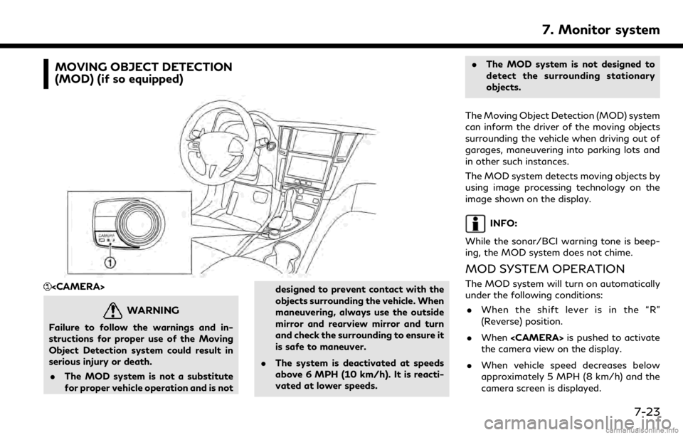
MOVING OBJECT DETECTION
(MOD) (if so equipped)
WARNING
Failure to follow the warnings and in-
structions for proper use of the Moving
Object Detection system could result in
serious injury or death.. The MOD system is not a substitute
for proper vehicle operation and is not designed to prevent contact with the
objects surrounding the vehicle. When
maneuvering, always use the outside
mirror and rearview mirror and turn
and check the surrounding to ensure it
is safe to maneuver.
. The system is deactivated at speeds
above 6 MPH (10 km/h). It is reacti-
vated at lower speeds. .
The MOD system is not designed to
detect the surrounding stationary
objects.
The Moving Object Detection (MOD) system
can inform the driver of the moving objects
surrounding the vehicle when driving out of
garages, maneuvering into parking lots and
in other such instances.
The MOD system detects moving objects by
using image processing technology on the
image shown on the display.
INFO:
While the sonar/BCI warning tone is beep-
ing, the MOD system does not chime.
MOD SYSTEM OPERATION
The MOD system will turn on automatically
under the following conditions: . When the shift lever is in the “R”
(Reverse) position.
. When
the camera view on the display.
. When vehicle speed decreases below
approximately 5 MPH (8 km/h) and the
camera screen is displayed.
7. Monitor system
7-23
Page 126 of 288

7. Monitor system
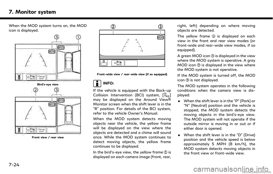
When the MOD system turns on, the MOD
icon is displayed.
Bird’s-eye view
Front view / rear view
Front-wide view / rear-wide view (if so equipped)
INFO:
If the vehicle is equipped with the Back-up
Collision Intervention (BCI) system, [
]
may be displayed on the Around View®
Monitor screen when the shift lever is in the
“R” position. For details of the BCI system,
refer to the vehicle Owner’s Manual.
When the MOD system detects moving
objects near the vehicle, the yellow frame
will be displayed on the view where the
objects are detected and a chime will sound
once. While the MOD system continues to
detect moving objects, the yellow frame
continues to be displayed.
In the bird’s-eye view, the yellow frame
is
displayed on each camera image (front, rear, right, left) depending on where moving
objects are detected.
The yellow frame
is displayed on each
view in the front and rear view modes (or
front-wide and rear-wide view modes, if so
equipped).
A green MOD icon
is displayed in the view
where the MOD system is operative. A gray
MOD icon
is displayed in the view where
the MOD system is not operative.
If the MOD system is turned off, the MOD
icon
is not displayed.
The MOD system operates in the following
conditions when the camera view is dis-
played: . When the shift lever is in the “P” (Park) or
“N” (Neutral) position and the vehicle is
stopped, the MOD system detects the
moving objects in the bird’s-eye view.
The MOD system will not operate if the
outside mirror is moving in or out or if
either door is opened.
. When the shift lever is in the “D” (Drive)
position and the vehicle speed is below
approximately 5 MPH (8 km/h), the
MOD system detects moving objects in
the front view or front-wide view.
7-24
Page 128 of 288

7. Monitor system
conditions and surrounding objects
such as:
— When there is low contrast between background and the moving objects.
— When there is blinking source of light.
— When strong light such as another vehicle’s headlight or sunlight is
present.
— When camera orientation is not in its usual position, such as when
mirror is folded.
— When there is dirt, water drops or snow on the camera lens.
— When the position of the moving objects in the display is not chan-
ged.
. The MOD system might detect flow-
ing water droplets on the camera lens,
white smoke from the muffler, moving
shadows, etc.
. The MOD system may not function
properly depending on the speed,
direction, distance or shape of the
moving objects. .
If your vehicle sustains damage to the
parts where the camera is installed,
leaving it misaligned or bent, the
sensing zone may be altered and the
MOD system may not detect objects
properly.
. When the temperature is extremely
high or low, the screen may not dis-
play objects clearly. This is not a
malfunction.
SYSTEM MAINTENANCE
CAUTION
.Do not use alcohol, benzine or thinner
to clean the camera. This will cause
discoloration. To clean the camera,
wipe with a cloth dampened with
diluted mild cleaning agent and then
wipe with a dry cloth.
. Do not damage the camera as the
monitor screen may be adversely
affected.
If dirt, rain or snow accumulates on any of
the cameras
, the MOD system may not
operate properly. Clean the camera by
wiping with a cloth dampened with a diluted
mild cleaning agent and then wiping with a
dry cloth.
7-26
Page 281 of 288

A
About route guidance .............................. 9-29
Adjusting the screen.................................... 7-6
Adjusting volume and settings.............. 2-10
Advanced Climate Control system.......... 3-7
Air conditioner
In-cabin microfilter...................................... 3-8
Air filter
In-cabin microfilter...................................... 3-8
App Garage screen ..................................... 6-2
App Garage Settings screen .................... 6-3
Around View® Monitor (AVM)............... 7-8
Around View® Monitor
system operation.......................................... 7-9
Audio operation precautions ................... 4-2
Audio operations....................................... 4-12
Audio Source bar setting ........................ 4-13
Audio system
Steering-wheel audio controls .............. 4-12
Automatic
Automatic climate control system.......... 3-6
Auxiliary (AUX) devices............................ 4-31B
Bluetooth® Hands-Free
Phone System .............................................. 5-2
Bluetooth® information .......................... 5-14
Bluetooth® streaming audio...... 4-10, 4-27
Building graphics ......................................... 9-6
C
Cabin air filter .............................................. 3-8
Camera aiding sonar function ............... 7-19
Canceling Route......................................... 9-34
CD/USB memory device care
and cleaning............................................... 4-34
Changing map view.................................... 9-9
Changing order of destination
and waypoints............................................ 9-37
Changing region......................................... 9-14
Changing scale of map .............................. 9-8
Clock settings............................................. 2-21
Command list.............................................. 10-7
Compact Disc (CD) player ............ 4-4, 4-19
Compressed Audio
Files (MP3/WMA/AAC)........................... 4-7
Connecting Bluetooth®
audio device................................................ 2-22
Connecting Bluetooth® device.............. 2-22Connecting Bluetooth®
Hands-free Phone....................................... 5-3
Connecting cellular phone ...................... 2-22
Connecting to Interactive
Voice Menu................................................. 8-17
Control buttons and functions................ 2-2
Current vehicle location........................... 9-59
Customer assistance ................................ 11-2D
Defroster switch
Rear window and outside mirror
defroster switch........................................... 3-9
Deleting stored item................................. 9-53
Destination screen .................................... 9-15
Display Settings......................................... 2-17
Display urgent traffic information ....... 9-46
Display View Bar....................................... 2-12
Displaying current vehicle location.......... 9-7
Download application................................ 6-2
Driver Assistance settings ...................... 8-33
Dual Display.................................................. 2-2
During a call.................................................. 5-5
Index
12-1
Page 283 of 288

Procedures after setting route.............. 9-27
R
Radio................................................... 4-2, 4-14
Rear window and outside mirror
defroster switch........................................... 3-9
RearView Monitor ....................................... 7-2
Recalculating route................................... 9-37
Receiving a call............................................. 5-4
Route calculation....................................... 9-63
Route guidance.............................. 9-29, 9-64
Route guidance settings.......................... 9-39
Route menu screen................................... 9-34
S
Safety information............................. 1-3, 9-3
Screen settings........................................... 2-17
Scrolling message or list.......................... 2-10
Searching for detour route using
traffic information..................................... 9-38
Searching from history ............................ 9-23
Searching from Stored Locations......... 9-24
Selecting item............................................. 2-10
Servicing heater and air conditioner...... 3-9
Setting at information on map.............. 9-13Setting by INFINITI
InTouch™ Services .................................... 9-25
Setting by phone number........................ 9-25
Setting city center..................................... 9-24
Setting detour route................................. 9-39
Setting freeway entrance/exit.............. 9-23
Setting from stored routes..................... 9-25
Setting home as destination .................. 9-21
Setting intersection .................................. 9-21
Setting point on map ............................... 9-27
Settings screen.......................................... 8-24
Shortcut menu............................................ 2-11
SiriusXM Traffic™ ....................................... 8-4
SiriusXM® Travel Link ............................... 8-4
Sonar system.............................................. 7-19
split screen .................................................. 9-10
Start-up screen............................................. 2-7
Steering
Steering-wheel-mounted controls for
audio ............................................................. 4-12
Steering-wheel switches........................... 2-6
Storing a location/route ........................ 9-48
Storing avoid area.................................... 9-50
Storing home location............................. 9-48
Storing location ........................................ 9-48
Storing route .............................................. 9-49
Subscription to INFINITI
InTouch™ Services .................................... 8-11
Switch
Rear window and outside mirror
defroster switch........................................... 3-9
T
Text message settings ............................. 5-10
Touch panel................................................... 2-8
Trademarks ................................................... 1-4
Traffic information on map.................... 9-47
Traffic information settings ................... 9-46
Transferring information to/from
address book .............................................. 9-55
U
Updating All Information Feeds .......... 8-19
Upper display.............................................. 2-11
Upper touch screen display
(upper display)............................................ 2-11
USB (Universal Serial Bus) connection
port ..................................................... 4-5, 4-21
USB/iPod® interface and Auxiliary
input jack ....................................................... 2-6
User edit screen......................................... 8-31
User registration....................................... 8-30
Index
12-3