light INFINITI QX50 2023 Owners Manual
[x] Cancel search | Manufacturer: INFINITI, Model Year: 2023, Model line: QX50, Model: INFINITI QX50 2023Pages: 548, PDF Size: 6.17 MB
Page 197 of 548
•Touch the one touch unlock sensor while
carrying the Intelligent Key with you. For
additional information, see “Unlocking
doors and fuel-filler door” (P. 3-12).
2. To open the fuel-filler door, push the right side of the fuel-filler door to release.
To lock, close the fuel-filler door securely and
lock the doors.
FUEL-FILLER CAP
WARNING
• Gasoline is extremely flammable and
highly explosive under certain condi-
tions. You could be burned or seriously
injured if it is misused or mishandled. Al-
ways stop the engine and do not smoke
or allow open flames or sparks near the
vehicle when refueling.
• Do not attempt to top off the fuel tank
after the fuel pump nozzle shuts off au-
tomatically. Continued refueling may
cause fuel overflow, resulting in fuel
spray and possibly a fire. •
Use only an original equipment type fuel-
filler cap as a replacement. It has a
built-in safety valve needed for proper
operation of the fuel system and emis-
sion control system. An incorrect cap can
result in a serious malfunction and pos-
sible injury. It could also cause the
Malfunction Indicator Light (MIL) to
come on.
• Never pour fuel into the throttle body to
attempt to start your vehicle.
• Do not fill a portable fuel container in the
vehicle or trailer. Static electricity can
cause an explosion of flammable liquid,
vapor or gas in any vehicle or trailer. To
reduce the risk of serious injury or death
when filling portable fuel containers:
– Always place the container on the
ground when filling.
– Do not use electronic devices when
filling.
– Keep the pump nozzle in contact with
the container while you are filling it.
– Use only approved portable fuel con-
tainers for flammable liquid.
CAUTION
• Do not use a fuel containing more than
15% ethanol in your vehicle. For addi-
tional information, see “Fuel recommen-
dation” (P. 10-4).
•
The Loose Fuel Cap warning message will
be displayed if the fuel-filler cap is not
properly tightened. It may take a few driv-
ing trips for the message to be displayed.
Failure to tighten the fuel-filler cap prop-
erly after the Loose Fuel Cap warning
is displayed may cause the Malfunction
Indicator Light (MIL) to illuminate.
• Failure to tighten the fuel-filler cap
properly may cause theMalfunc-
tion Indicator Light (MIL) to illuminate.
If the
light illuminates because the
fuel-filler cap is loose or missing, tighten
or install the cap and continue to drive
the vehicle. The
light should turn off
after a few driving trips. If thelight
does not turn off after a few driving
trips, have the vehicle inspected. It is rec-
ommended that you visit an INFINITI
retailer for this service.
Pre-driving checks and adjustments3-29
Page 198 of 548
•For additional information, see “Malfunc-
tion Indicator Light (MIL)” (P. 2-15).
• If fuel is spilled on the vehicle body, flush
it away with water to avoid paint
damage.
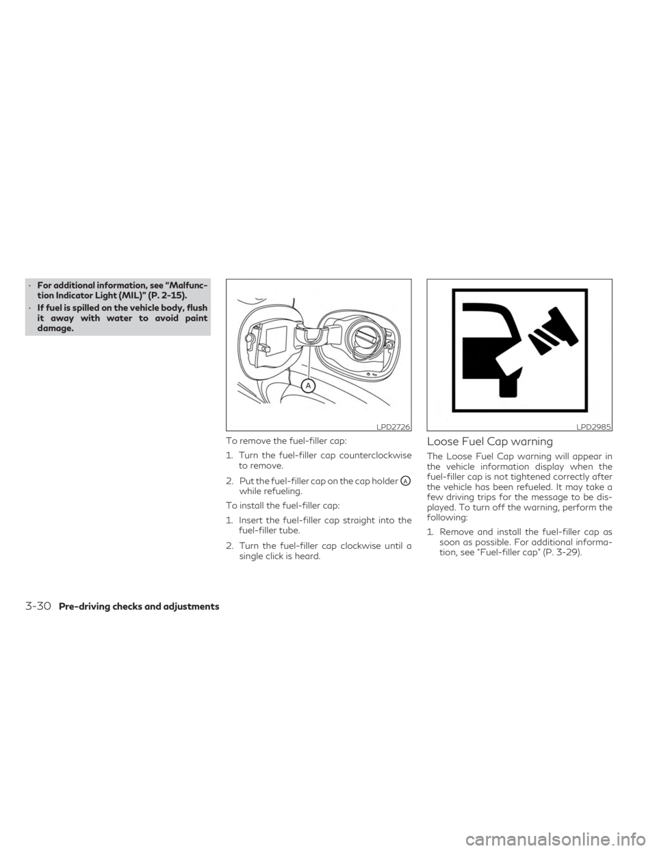
To remove the fuel-filler cap:
1. Turn the fuel-filler cap counterclockwiseto remove.
2. Put the fuel-filler cap on the cap holder
OAwhile refueling.
To install the fuel-filler cap:
1. Insert the fuel-filler cap straight into the fuel-filler tube.
2. Turn the fuel-filler cap clockwise until a single click is heard.
Loose Fuel Cap warning
The Loose Fuel Cap warning will appear in
the vehicle information display when the
fuel-filler cap is not tightened correctly after
the vehicle has been refueled. It may take a
few driving trips for the message to be dis-
played. To turn off the warning, perform the
following:
1. Remove and install the fuel-filler cap assoon as possible. For additional informa-
tion, see “Fuel-filler cap” (P. 3-29).
LPD2726LPD2985
3-30Pre-driving checks and adjustments
Page 202 of 548
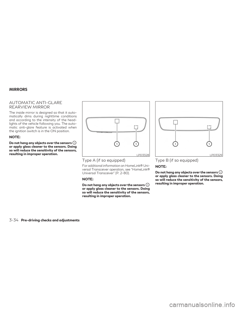
AUTOMATIC ANTI-GLARE
REARVIEW MIRROR
The inside mirror is designed so that it auto-
matically dims during nighttime conditions
and according to the intensity of the head-
lights of the vehicle following you. The auto-
matic anti-glare feature is activated when
the ignition switch is in the ON position.
NOTE:
Do not hang any objects over the sensorsO1
or apply glass cleaner to the sensors. Doing
so will reduce the sensitivity of the sensors,
resulting in improper operation.
Type A (if so equipped)
For additional information on HomeLink® Uni-
versal Transceiver operation, see “HomeLink®
Universal Transceiver” (P. 2-80).
NOTE:
Do not hang any objects over the sensorsO1
or apply glass cleaner to the sensors. Doing
so will reduce the sensitivity of the sensors,
resulting in improper operation.
Type B (if so equipped)
NOTE:
Do not hang any objects over the sensorsO1
or apply glass cleaner to the sensors. Doing
so will reduce the sensitivity of the sensors,
resulting in improper operation.
LPD3328LPD3329
MIRRORS
3-34Pre-driving checks and adjustments
Page 204 of 548

Power folding outside mirrors (if so
equipped)
CAUTION
• Do not touch the mirrors while they are
moving. Your hand may be pinched, and
the mirror may malfunction.
• Do not drive with the mirrors stored. You
will be unable to see behind the vehicle.
Push the switch
O2to open or the switchO1
to close the mirrors. If one of the mirrors are manually operated or
bumped, the mirror body can become loose
at the pivot point. To correct electronic mirror
operation, cycle the mirrors by pushing the
switch
O1until completely closed, then push
the switch
O2until the mirrors are in the open
position.
Automatic folding outside mirrors
(if so equipped)
The outside mirrors fold automatically when
the vehicle is locked with the Intelligent Key
or by using the request switch. The outside
mirrors unfold automatically when the igni-
tion switch is placed in the ON position and
the power folding mirror switch is in position
O2.
Automatic anti-glare outside mirror
(if so equipped)
The outside mirror will automatically dim dur-
ing nighttime conditions to reduce the glare
from the headlights of trailing vehicles. The
automatic anti-glare feature operates only
when the ignition switch is placed in the ON
position. The automatic anti-glare feature will be on
when starting the vehicle. The indicator light
on the automatic anti-glare rearview mirror
will illuminate when the automatic anti-glare
feature is operating.
For additional information, see “Automatic
anti-glare rearview mirror” (P. 3-34).
Heated mirrors
The electric control type outside mirrors can
be heated to defrost, defog, or de-ice for
improved visibility. For additional informa-
tion, see “Rear window defroster, outside
mirror defroster (if so equipped), and wiper
deicer (if so equipped) switch” (P. 2-39).
Reverse tilt-down feature (if so
equipped)
The reverse tilt-down feature will turn both
outside mirror surfaces downward to provide
better rear visibility close to the vehicle when
the mirror control switch is in either the L or R
position.
The mirrors automatically return to their origi-
nal position when you shift out of R (Reverse).
LPD2303
3-36Pre-driving checks and adjustments
Page 206 of 548

1. Adjust the driver's seat, steering column(if so equipped), and outside mirrors to the
desired positions by manually operating
each adjusting switch. For additional in-
formation, see “Seats” (P. 1-2), “Steering
wheel” (P. 3-31) and “Outside mirrors”
(P. 3-35).
2. Push the SET switch and, within 5 sec- onds, push the memory switch (1 or 2).
The indicator light for the pushed memory
switch will come on and stay on for ap-
proximately 5 seconds.
The chime will sound when the memory is
stored.
NOTE:
If a new memory position is stored in the
same memory switch, the previous memory
position will be overwritten by the new
stored position.
Confirming memory storage
• Push the SET switch.
• If a memory position has been stored in the switch (1 or 2) then the indicator light for
the respective switch will stay on for ap-
proximately 5 seconds.
Linking log-in function to a stored
memory position
The log-in function can be linked to a stored
memory position with the following
procedure.
1. Place the ignition switch in the ON posi- tion while carrying the Intelligent Key that
was registered to the vehicle with a log-in
function.
NOTE:Make sure the Intelligent Keys are far apart.
Otherwise, the vehicle may detect the
wrong Intelligent Key.
2. Adjust the position of the driver’s seat, steering column (if so equipped) and out-
side mirrors. For additional information,
see “Seats” (P. 1-2), “Steering wheel”
(P. 3-31) and “Outside mirrors” (P. 3-35).
3. Place the ignition switch in the OFF position.
The next time you log in (selecting the user on
the display) after placing the ignition switch in
the ON position while carrying the Intelligent
Key, the system will automatically adjust to
the memorized driving position. For additional information, see “Log-in func-
tion” (P. 3-18) and the separate INFINITI In-
Touch™ Owner’s Manual.
ENTRY/EXIT FUNCTION
This system is designed so that the driver's
seat and steering column (if so equipped) will
automatically move when the vehicle is en-
gaged in the P (Park) position. This allows the
driver to easily get in and out of the driver’s
seat.
The driver’s seat will slide backward and the
steering column (if so equipped) will move up
when the ignition is switched to OFF and the
driver’s door is opened.
The driver’s seat and steering wheel will re-
turn to the previous position when the igni-
tion is switched to ON.
The entry/exit function can be adjusted or
canceled through the “Comfort & Conve-
nience” options of the “Settings” menu in the
lower touch-screen display by performing the
following:
• Switch the Lift Steering upon Exit from ON
to OFF.
• Switch the Slide Driver Seat Back on Exit from ON to OFF.
3-38Pre-driving checks and adjustments
Page 217 of 548
3. Touch the “Display Settings” key. Select apreferred item, “Brightness”, “Contrast”,
Tint”, “Color”, and “Black Level” of the
RearView Monitor and adjust the value by
touching the “+” or “-” key.
You can also press the
button and either
turn or move the INFINITI controller to adjust
the day/night settings. Pressing the
button again will switch the screen to AUTO
mode. While the adjustment screen is shown
on the upper display you can also touch either
“+” or “-” key.
The upper and lower display screens can be
turned on or off by pressing and holding the
button.
NOTE:
Do not adjust the Brightness, Contrast, Tint,
Color, and Black Level of the RearView
Monitor while the vehicle is moving. Make
sure the parking brake is firmly applied.
HOW TO TURN ON AND OFF
PREDICTED COURSE LINES
To toggle on and off the predicted course
lines while in the P (Park) position:
1. Press the MENU button.
2. Touch the “Settings” key. 3. Touch the “Camera” key.
4. Touch the “Predicted Course Lines” key to
turn the feature on or off.
When the predicted course lines are
turned on, the indicator light is on.
REARVIEW MONITOR SYSTEM
LIMITATIONS
WARNING
Listed below are the system limitations for
RearView Monitor. Failure to operate the
vehicle in accordance with these system
limitations could result in serious injury or
death.
• The system cannot completely eliminate
blind spots and may not show every
object.
• Underneath the bumper and the corner
areas of the bumper cannot be viewed on
the RearView Monitor because of its
monitoring range limitation. The system
will not show small objects below the
bumper, and may not show objects close
to the bumper or on the ground.
• Objects viewed in the RearView Monitor
differ from actual distance because a
wide-angle lens is used. •
Objects in the RearView Monitor will ap-
pear visually opposite compared to when
viewed in the rearview and outside
mirrors.
• Use the displayed lines as a reference.
The lines are highly affected by the num-
ber of occupants, fuel level, vehicle posi-
tion, road conditions and road grade.
• Make sure that the liftgate is securely
closed when backing up.
• Do not put anything on the rearview
camera. The rearview camera is installed
above the license plate.
• When washing the vehicle with high
pressure water, be sure not to spray it
around the camera. Otherwise, water
may enter the camera unit causing water
condensation on the lens, a malfunction,
fire or an electric shock.
• Do not strike the camera. It is a precision
instrument. Otherwise, it may malfunc-
tion or cause damage resulting in a fire or
an electric shock.
Monitor, climate, audio, phone and voice recognition systems4-9
Page 218 of 548
The following are operating limitations and
do not represent a system malfunction:
• When the temperature is extremely high orlow, the screen may not clearly display
objects.
• When strong light directly shines on the camera, objects may not be displayed
clearly.
• Vertical lines may be seen in objects on the screen. This is due to strong reflected light
from the bumper.
• The screen may flicker under fluorescent light.
• The colors of objects on the RearView Monitor may differ somewhat from the ac-
tual color of objects.
• Objects on the monitor may not be clear in a dark environment.
• There may be a delay when switching be- tween views.
• If dirt, rain or snow accumulate on the cam- era, the RearView Monitor may not display
objects clearly. Clean the camera.
• Do not use wax on the camera lens. Wipe off any wax with a clean cloth dampened
with a diluted mild cleaning agent, then
wipe with a dry cloth.
SYSTEM MAINTENANCE
CAUTION
• Do not use alcohol, benzine or thinner
to clean the camera. This will cause
discoloration.
• Do not damage the camera as the moni-
tor screen may be adversely affected. If dirt, rain or snow accumulates on the cam-
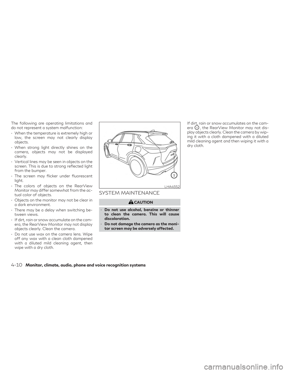
era
O1, the RearView Monitor may not dis-
play objects clearly. Clean the camera by wip-
ing it with a cloth dampened with a diluted
mild cleaning agent and then wiping it with a
dry cloth.
LHA4552
4-10Monitor, climate, audio, phone and voice recognition systems
Page 221 of 548
AROUND VIEW® MONITOR
SYSTEM OPERATION
With the engine running, move the shift lever
to the R (Reverse) position or press the
CAMERA button to operate the Around
View® Monitor. When activating the Around
View® Monitor, the guide lines, the icons
and the messages may not be displayed
immediately.
When the camera is first activated with the
bird’s-eye view in the display, a red icon will
flash on the upper display. This indicates that
the sonar system is activated. For additional
information on the front and rear sonar sys-
tem, see “Front and rear sonar system”
(P. 5-147).
Available views
WARNING
• The distance guide lines and the vehicle
width lines should be used as a reference
only when the vehicle is on a paved, level
surface. The apparent distance viewed
on the monitor may be different than the
actual distance between the vehicle and
displayed objects.
• Use the displayed lines and the bird’s-
eye view as a reference. The lines and the
bird’s-eye view are greatly affected by
the number of occupants, cargo, fuel
level, vehicle position, road condition
and road grade.
• If the tires are replaced with different
sized tires, the predicted course lines and
the bird's-eye view may be displayed
incorrectly.
• When driving the vehicle up a hill, objects
viewed in the monitor are further than
they appear. When driving the vehicle
down a hill, objects viewed in the monitor
are closer than they appear. •
Objects in the rear view will appear visu-
ally opposite compared to when viewed
in the monitor and outside mirrors.
• Use the mirrors or actually look to prop-
erly judge distances to other objects.
• On a snow-covered or slippery road,
there may be a difference between the
predicted course lines and the actual
course line.
• The vehicle width and predicted course
lines are wider than the actual width and
course.
• The displayed lines will appear slightly
off to the right, because the rearview
camera is not installed in the rear center
of the vehicle.
Monitor, climate, audio, phone and voice recognition systems4-13
Page 223 of 548
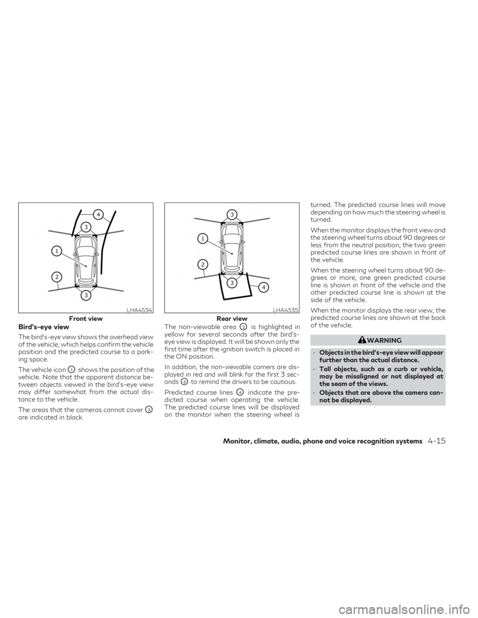
Bird’s-eye view
The bird's-eye view shows the overhead view
of the vehicle, which helps confirm the vehicle
position and the predicted course to a park-
ing space.
The vehicle icon
O1shows the position of the
vehicle. Note that the apparent distance be-
tween objects viewed in the bird's-eye view
may differ somewhat from the actual dis-
tance to the vehicle.
The areas that the cameras cannot cover
O2
are indicated in black. The non-viewable area
O2is highlighted in
yellow for several seconds after the bird’s-
eye view is displayed. It will be shown only the
first time after the ignition switch is placed in
the ON position.
In addition, the non-viewable corners are dis-
played in red and will blink for the first 3 sec-
onds
O3to remind the drivers to be cautious.
Predicted course linesO4indicate the pre-
dicted course when operating the vehicle.
The predicted course lines will be displayed
on the monitor when the steering wheel is turned. The predicted course lines will move
depending on how much the steering wheel is
turned.
When the monitor displays the front view and
the steering wheel turns about 90 degrees or
less from the neutral position, the two green
predicted course lines are shown in front of
the vehicle.
When the steering wheel turns about 90 de-
grees or more, one green predicted course
line is shown in front of the vehicle and the
other predicted course line is shown at the
side of the vehicle.
When the monitor displays the rear view, the
predicted course lines are shown at the back
of the vehicle.
WARNING
• Objects in the bird's-eye view will appear
further than the actual distance.
• Tall objects, such as a curb or vehicle,
may be misaligned or not displayed at
the seam of the views.
• Objects that are above the camera can-
not be displayed.
LHA4534
Front view
LHA4535
Rear view
Monitor, climate, audio, phone and voice recognition systems4-15
Page 229 of 548
Designs and items displayed on the screen
may vary depending on model.
Moving Object Detection:
When this item is turned on, the MOD is
activated. When this item is turned off
(indicator turns off), the MOD system is
deactivated.
MOD Volume:
Adjusts the MOD volume between “High”,
“Medium” or “Low” by touching the key on the
display screen.
Unviewable Area Reminder:
With this item turned on, the non-viewable
area is highlighted in yellow for three seconds
after the bird's-eye view is displayed. It will
only be shown the first time after the ignition
switch is placed in the ON position.
Predicted Course Lines:
When this item is turned on, the predicted
course lines are displayed in the front view,
rear view and bird's-eye view.
Auto Show Sonar Image:
When the sonar detects an object while this
item is turned on, the Around View® Monitor
will interrupt the current view in the display to
show the surrounding area of the vehicle.
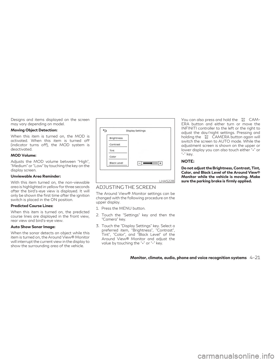
ADJUSTING THE SCREEN
The Around View® Monitor settings can be
changed with the following procedure on the
upper display.
1. Press the MENU button.
2. Touch the “Settings” key and then the“Camera” key.
3. Touch the “Display Settings” key. Select a preferred item, “Brightness”, ”Contrast”,
Tint”, “Color”, and “Black Level” of the
Around View® Monitor and adjust the
value by touching the “+” or “-” key. You can also press and hold the
CAM-
ERA button and either turn or move the
INFINITI controller to the left or the right to
adjust the day/night settings. Pressing and
holding the
CAMERA button again will
switch the screen to AUTO mode. While the
adjustment screen is shown on the upper or
lower display you can also touch either “+” or
“-” key.
NOTE:
Do not adjust the Brightness, Contrast, Tint,
Color, and Black Level of the Around View®
Monitor while the vehicle is moving. Make
sure the parking brake is firmly applied.
LHA5228
Monitor, climate, audio, phone and voice recognition systems4-21