mirror INFINITI QX56 2006 Factory Owner's Manual
[x] Cancel search | Manufacturer: INFINITI, Model Year: 2006, Model line: QX56, Model: INFINITI QX56 2006Pages: 3383, PDF Size: 51.76 MB
Page 2233 of 3383

GW-88
REAR WINDOW DEFOGGER
Revision: November 20092006 QX56
2. CHECK DOOR MIRROR DEFOGGER POWER SUPPLY CIRCUIT 2
Check voltage between IPDM E/R connector and ground.
OK or NG
OK >> GO TO 3.
NG >> Replace IPDM E/R. Refer to PG-30, "
Removal and
Installation of IPDM E/R" .
3. CHECK DOOR MIRROR DEFOGGER CIRCUIT
1. Turn ignition switch OFF.
2. Disconnect IPDM E/R and door mirror LH or RH.
3. Check continuity between IPDM E/R connector E120 terminal 23 and door mirror connector D4 (LH) or D107 (RH) terminal 10.
OK or NG
OK >> GO TO 4.
NG >> Repair or replace harness.
4. CHECK DOOR MIRROR DEFOGGER GROUND CIRCUIT
Check continuity between each door mirror connector D4 (LH) or
D107 (RH) terminal 11 and ground.
OK or NG
OK >> GO TO 5.
NG >> Repair or replace harness.
5. CHECK DOOR MIRROR DEFOGGER
Check continuity between each door mirror LH or RH terminals 10
and 11.
OK or NG
OK >> Check the condition of the harness and the connector.
NG >> Replace malfunctioning door mirror LH or RH. Refer to GW-94, "
Door Mirror Assembly" .
Connector Terminals
ConditionVoltage (V)
(Approx.)
(+) (-)
E120 23 Ground Rear window defogger
switch ON
Battery voltage
Rear window defogger
switch OFF 0
LIIA0977E
23 - 10
: Continuity should exist.
WIIA0529E
11 - Ground: Continuity should exist.
LIIA1454E
10 - 11 : Continuity should exist.
LIIA2725E
Page 2234 of 3383

REAR WINDOW DEFOGGERGW-89
C
DE
F
G H
J
K L
M A
B
GW
Revision: November 2009 2006 QX56
Door Mirror LH (Door Mirror Defogger) Circuit CheckEIS005Z1
1. CHECK DOOR MIRROR DEFOGGER POWER SUPPLY CIRCUIT
1. Turn ignition switch OFF.
2. Disconnect door mirror LH.
3. Turn ignition switch ON.
4. Check voltage between door mirror LH connector and ground.
OK or NG
OK >> GO TO 2.
NG >> Repair or replace harness.
2. CHECK DOOR MIRROR DEFOGGER GROUND CIRCUIT
1. Turn ignition switch OFF.
2. Check continuity between door mirror LH connector D4 terminal 11 and ground.
OK or NG
OK >> GO TO 3.
NG >> Repair or replace harness.
3. CHECK DOOR MIRROR DEFOGGER
Check continuity between door mirror LH terminals 10 and 11.
OK or NG
OK >> Repair or replace harness.
NG >> Replace door mirror LH. Refer to GW-94, "
Door Mirror
Assembly" .
ConnectorTe r m i n a l s
ConditionVoltage (V)
(Approx.)
(+) (-)
D4 10 Ground Rear window defogger
switch ON
Battery voltage
Rear window defogger
switch OFF 0
LIIA1456E
11 - Ground
: Continuity should exist.
LIIA1458E
10 - 11 : Continuity should exist.
LIIA2725E
Page 2235 of 3383

GW-90
REAR WINDOW DEFOGGER
Revision: November 20092006 QX56
Door Mirror RH (Door Mirror Defogger) Circuit CheckEIS005Z2
1. CHECK DOOR MIRROR DEFOGGER POWER SUPPLY CIRCUIT
1. Turn ignition switch OFF.
2. Disconnect door mirror RH.
3. Turn ignition switch ON.
4. Check voltage between door mirror RH connector and ground.
OK or NG
OK >> GO TO 2.
NG >> Repair or replace harness.
2. CHECK DOOR MIRROR DEFOGGER GROUND CIRCUIT
1. Turn ignition switch OFF.
2. Check continuity between door mirror RH connector D107 termi- nal 11 and ground.
OK or NG
OK >> GO TO 3.
NG >> Repair or replace harness.
3. CHECK DOOR MIRROR DEFOGGER
Check continuity between each door mirror RH terminals 10 and 11.
OK or NG
OK >> Repair or replace harness.
NG >> Replace door mirror RH. Refer to GW-94, "
Door Mirror
Assembly" .
Rear Window Defogger Signal CheckEIS005Z3
1. CHECK AV COMMUNICATION LINE
AV communication line check is executed. Refer to AV- 4 4 , "
Audio Communication Line Check" .
OK or NG
OK >> GO TO 2.
NG >> Replace display control unit. Refer to AV- 1 6 7 , "
DISPLAY CONTROL UNIT" .
ConnectorTerminals
ConditionVoltage (V)
(Approx.)
(+) (-)
D107 10 Ground Rear window defogger
switch ON
Battery voltage
Rear window defogger
switch OFF 0
LIIA1456E
11 - Ground
: Continuity should exist.
LIIA1458E
10 - 11 : Continuity should exist.
LIIA2725E
Is rear window defogger displayed on the display?
Page 2238 of 3383

DOOR MIRRORGW-93
C
DE
F
G H
J
K L
M A
B
GW
Revision: November 2009 2006 QX56
DOOR MIRRORPFP:96301
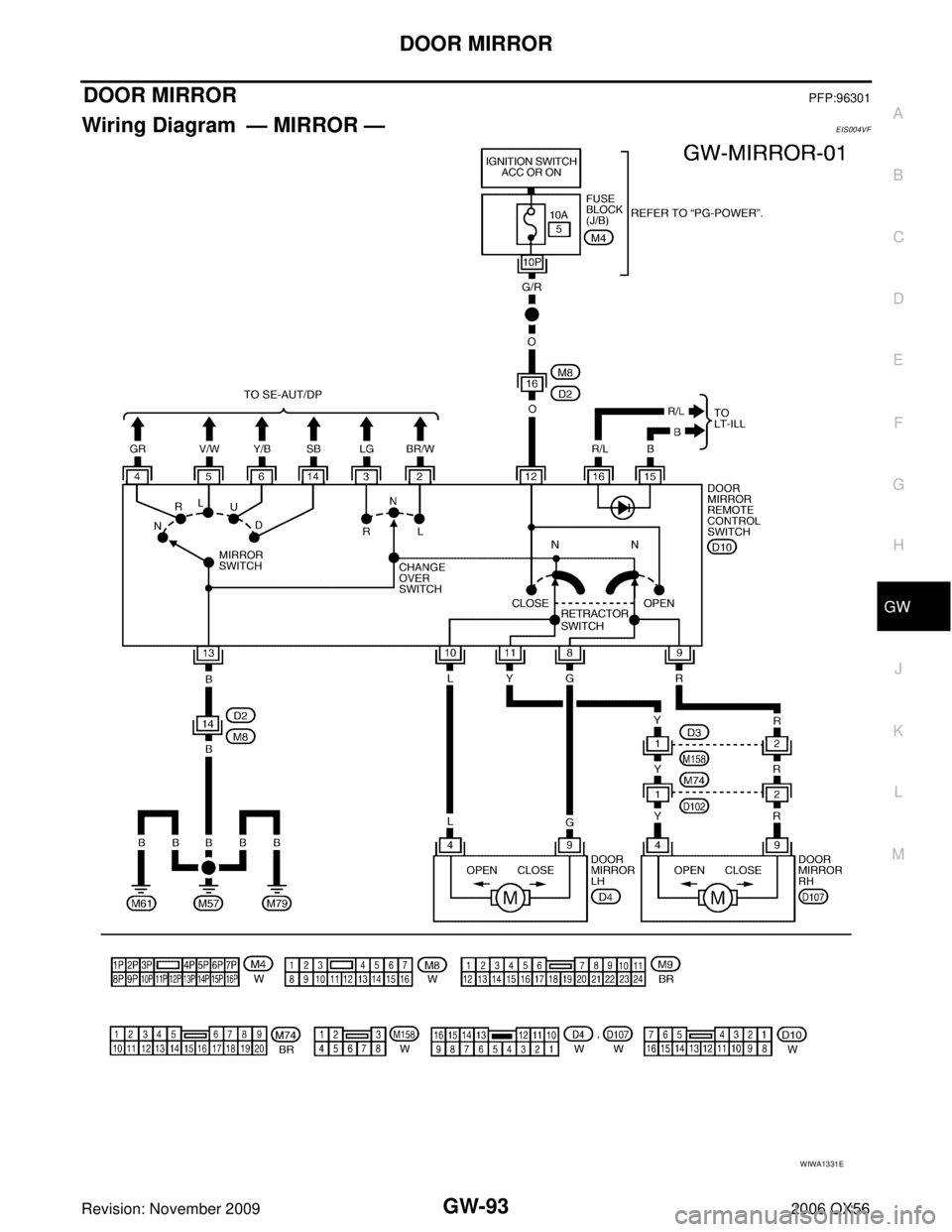
Wiring Diagram — MIRROR —EIS004VF
WIWA1331E
Page 2239 of 3383

GW-94
DOOR MIRROR
Revision: November 20092006 QX56
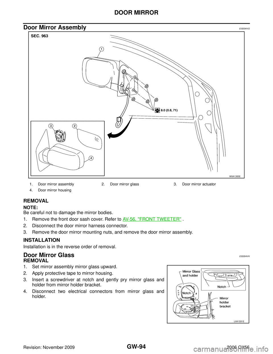
Door Mirror AssemblyEIS004VG
REMOVAL
NOTE:
Be careful not to damage the mirror bodies.
1. Remove the front door sash cover. Refer to AV- 5 6 , "
FRONT TWEETER" .
2. Disconnect the door mirror harness connector.
3. Remove the door mirror mounting nuts, and remove the door mirror assembly.
INSTALLATION
Installation is in the reverse order of removal.
Door Mirror GlassEIS004VH
REMOVAL
1. Set mirror assembly mirror glass upward.
2. Apply protective tape to mirror housing.
3. Insert a screwdriver at notch and gently pry mirror glass and holder from mirror holder bracket.
4. Disconnect two electrical connectors from mirror glass and holder.
WIIA1365E
1. Door mirror assembly 2. Door mirror glass 3. Door mirror actuator
4. Door mirror housing
LIIA1591E
Page 2240 of 3383

DOOR MIRRORGW-95
C
DE
F
G H
J
K L
M A
B
GW
Revision: November 2009 2006 QX56
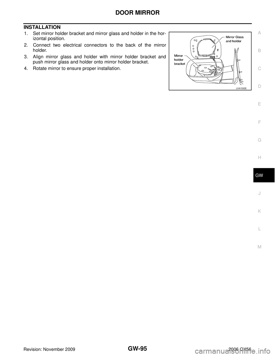
INSTALLATION
1. Set mirror holder bracket and mirror glass and holder in the hor-
izontal position.
2. Connect two electrical connectors to the back of the mirror holder.
3. Align mirror glass and holder with mirror holder bracket and push mirror glass and holder onto mirror holder bracket.
4. Rotate mirror to ensure proper installation.
LIIA1592E
Page 2241 of 3383

GW-96
DOOR MIRROR
Revision: November 20092006 QX56
Page 2243 of 3383

IDX-2
ALPHABETICAL INDEX
Numerics
2-4WD shift solenoid valve ..... TF-94
, TF-154, TF-167
4WD - Wiring diagram ....................................... TF-24
4WD shift switch ................................................ TF-66
4WD solenoid valve ................ TF-90, TF-154, TF-167
4WD system description .................................... TF-15
4WD system diagram ........................................ TF-19
A
A/C air flow ...................................................... ATC-30
A/C compressor clutch removal and installation .. ATC-
176
A/C compressor mounting ............................. ATC-175
A/C compressor precaution ............................. ATC-11
A/C compressor special service tool ................ ATC-14
A/C control operation (auto A/C) ...................... ATC-27
A/C diagnostic work flow (auto A/C) .............. ATC-130
A/C evaporator ............................................... ATC-184
A/C HFC134a (R134a) system identification ..... ATC-6
A/C HFC134a (R134a) system precaution ........ ATC-5
A/C HFC134a (R134a) system service procedure ATC-
171
A/C HFC134a (R134a) system service tools ... ATC-14
A/C HFC134a system service equipment precaution ...
ATC-11
A/C lubricant (R134a) ...................................... ATC-22
A/C lubrication oil ............................................. ATC-22
A/C operational check ....................... ATC-58, ATC-60
A/C self-diagnoses (auto A/C) ........ ATC-56, ATC-130
A/C service data specification ........................ ATC-191
A/C trouble diagnoses (auto A/C) .................... ATC-34
A/C, A - Wiring diagram ................................... ATC-44
A/T fluid checking ...................... AT-12, AT-51, MA-22
A/T fluid cooler cleaning .................................... AT-14
A/T fluid replacement ............................. AT-12, MA-24
A/T fluid temperature sensor ........................... AT-127
A/T IND - Wiring diagram .................................... DI-41
A/T indicator ........................................................ DI-41
A/T shift lock system ........................................ AT-221
A/T trouble diagnoses ........................................ AT-42
ABS - Wiring diagram ..................................... BRC-16
ABS (anti-lock brake system) ........................... BRC-7
Accelerator control system ............................... ACC-3
Accelerator pedal position (APP) sensor . EC-547, EC-
553, EC-567
Accelerator pedal released position learning ..... EC-78
AF1B1-Wiring diagram EC-216, EC-225, EC-234, EC-
244, EC-577
AF1B2-Wiring diagram EC-218, EC-227, EC-236, EC-
246, EC-579
AF1HB1-Wiring diagram .................................. EC-157
AF1HB2-Wiring diagram .................................. EC-159
Aiming adjustment .................................. LT-29, LT-78
Air bag .............................................................. SRS-3
Air bag precautions .............................................. AV-4
Air cleaner and air duct ..................................... EM-15
Air cleaner filter replacement ................ EM-16, MA-16
Air conditioner cut control ................................. EC-28
Air flow meter - See Mass air flow sensor EC-171, EC-
180
Air fuel ratio sensor 1 .. EC-213, EC-223, EC-232, EC-
241, EC-575
Air fuel ratio sensor 1 heater ........................... EC-156
Air mix. door motor .......................................... ATC-70
Ambient sensor ............................. ATC-134, ATC-145
Angular tightening application ............................. EM-4
Antenna .............................................................. AV-60
APPS1 - Wiring diagram ................................. EC-549
APPS2 - Wiring diagram ................................. EC-555
APPS3 - Wiring diagram ................................. EC-569
ASC/BS - Wiring diagram ............................... EC-513
ASC/SW - Wiring diagram .............................. EC-496
ASCBOF - Wiring diagram .............................. EC-587
ASCD ................................................................ EC-29
ASCD (automatic speed control device) ........... ACS-3
ASCD brake switch ........................... EC-511, EC-586
ASCD indicator lamp ....................................... EC-593
ASCD steering switch ..................................... EC-494
ASCIND - Wiring diagram ............................... EC-594
ATP switch ............................ TF-107, TF-110, TF-115
Audio .................................................................... AV-6
AUDIO - Wiring diagram .................................... AV-11
AUT/DP - Wiring diagram .................................. SE-16
Auto air conditioner - Wiring diagram .............. ATC-44
Auto anti-dazzling inside mirror ........... GW-72, GW-73
Autolamp ............................................................ LT-47
Automatic amplifier ......................................... ATC-61
Automatic drive positioner .................................. SE-11
Automatic transmission number .......................... GI-49
B
Back door ........................................................... BL-99
Back door trim ..................................................... EI-32
Back sonar .......................................................... DI-60
BACK/L - Wiring diagram ................................. LT-109
Back-up lamp ................................................... LT-109
Ball joint (front) ................................................ FSU-15
Basic inspection ................................................ EC-71
Battery ................................................................. SC-4
Battery/Starting/Charging System Tester SC-6, SC-12,
SC-19
BCM (Body control module) ................ BCS-3, AV-109
Block heater ...................................................... EM-78
Blower motor ................................... ATC-93, ATC-149
Body alignment ................................................ BL-172
Body component parts ..................................... BL-161
Body construction ............................................ BL-171
Body exterior paint color .................................. BL-160
Body mounting ................................................. BL-159
Body repair ....................................................... BL-160
Body sealing .................................................... BL-168
Bose speaker amp. .............................................. AV-8
Brake booster .................................................... BR-17
Brake fluid level ................................................. MA-28
Brake hydraulic line ........................................... BR-12
Page 2244 of 3383

IDX-3
A
C
D E
F
G H
I
J
K L
B
IDX
ALPHABETICAL INDEX
Brake inspection ................................................
MA-28
Brake lines and cables inspection ..................... MA-28
Brake master cylinder ....................................... BR-15
Brake switch ...................................... EC-511, EC-523
BRK/SW - Wiring diagram ............................... EC-524
Bulb specifications ........................................... LT-175
Bumper, front ...................................................... EI-13
Bumper, rear ....................................................... EI-15
C
Cabin air filter .................................................... MA-21
Camshaft ........................................................... EM-46
Camshaft inspection .......................................... EM-50
Camshaft position sensor (PHASE) ................ EC-347
CAN - Wiring diagram EC-152, AT-96, AT-97, LAN-28,
LAN-39
, LAN-57, LAN-79, LAN-98
CAN communication EC-31, EC-151, EC-154, TF-113,
RSU-6
Canister-See EVAP canister ............................. EC-35
Center case (Transfer) ....................... TF-154, TF-167
CHARGE - Wiring diagram ............................... SC-18
Charging system ............................................... SC-17
Chassis and body maintenance ........................ MA-21
Chassis and body maintenanceSchedule 1 ........ MA-8
Chassis and body maintenanceSchedule 2 ...... MA-10
CHIME - Wiring diagram ..................................... DI-46
Circuit breaker ................................................... PG-17
Clock ................................................................... DI-71
CLOCK - Wiring diagram .................................... DI-71
Closed loop control ............................. EC-25, EC-470
Closed loop control (Bank 1) ........................... EC-470
Closed loop control (Bank 2) ........................... EC-470
Clutch drum (Transfer) ....................... TF-154, TF-167
Clutch pressure switch (Transfer) ...... TF-154, TF-167
Coil spring (front) ............................................. FSU-10
Collision diagnosis .......................................... SRS-60
Combination lamp, front, removal and installation . LT-
31
Combination lamp, rear, removal and installation .. LT-
125
Combination meter ................................................ DI-5
Combination switch .......................................... LT-100
COMBSW - Wiring diagram ............................. LT-100
COMM - Wiring diagram ................................... AV-97
COMPAS - Wiring diagram ................................. DI-27
Compass ............................................................. DI-26
Component Location (auto A/C) ...................... ATC-40
Compressor clutch removal and installation . ATC-176
Compressor mounting ................................... ATC-175
Compressor precaution ................................... ATC-11
Compressor special service tool ..................... ATC-14
Condenser ..................................................... ATC-182
Connecting rod .................................................. EM-96
Connecting rod bearing clearance .................... EM-96
Connecting rod bushing clearance .................... EM-96
Console box - See Instrument panel ................... IP-10
CONSULT for VDC ......................................... BRC-28
CONSULT-II for engine ................................... EC-114
Control units (terminal arrangement) ................. PG-71
Control valve (A/T) ............................................. AT-36
Control valve (Transfer) ...................... TF-154, TF-167
Converter housing installation ............ AT-245, AT-249
COOL/F - Wiring diagram ................................ EC-476
Coolant mixture ratio ......................................... MA-12
Coolant replacement ............................ CO-10, MA-13
Cooling circuit (engine) ........................................ CO-8
Cooling fan ........................................................ CO-17
Cooling fan control ........................................... EC-473
Cooling fan motor ............................................ EC-482
Cooling unit (A/C evaporator) ....... ATC-153, ATC-184
Corrosion protection ......................................... BL-165
Crankcase ventilation system - See Positive crankcase
ventilation .......................................................... EC-45
Crankshaft ......................................................... EM-79
Crankshaft position sensor (POS) ................... EC-340
Crash zone sensor .......................................... SRS-55
Cylinder block .................................................... EM-78
Cylinder block boring ......................................... EM-99
D
D/LOCK - Wiring diagram ................................... BL-19
Data link connector for Consult ......... EC-116, EC-128
Daytime light system .......................................... LT-33
Daytime running light - See Daytime light system .. LT-
33
DEF - Wiring diagram ....................................... GW-77
Diagnosis sensor unit ...................................... SRS-58
Diagnostic trouble code (DTC) for OBD system . EC-8,
EC-52
Diagnostic trouble code (DTC) inspection priority chart
EC-89
Differential carrier assembly ............................ RFD-15
Differential gear oil replacement ........................ MA-26
Dimensions ......................................................... GI-50
Direct clutch solenoid valve ................ AT-147, AT-149
Display and amp.assembly .............................. ATC-61
Display Control Unit ........................................... AV-86
Display Unit ....................................................... AV-86
Dome light - See Interior lamp .......................... LT-134
Door glass .......................................... GW-65, GW-68
Door lock .......................................................... BL-131
Door mirror lamp ............................................... LT-134
Door trim .............................................................. EI-32
Door, front ........................................... BL-128, GW-65
Door, rear ........................................... BL-128, GW-68
Drive belt ........................................................... EM-13
Drive chain (Transfer) ......................... TF-149, TF-176
Drive pinion diff. inspection .............................. RFD-18
Drive shaft (rear) ................................................ RAX-7
Driver air bag ................................................... SRS-46
DTC work support ............................................ EC-124
DTRL - Wiring diagram ....................................... LT-37
Duct and grilles .............................................. ATC-166
DVD - Wiring Diagram ....................................... AV-78
DVD Entertainment System ............................... AV-75
DVD Player ........................................................ AV-76
Page 2247 of 3383

IDX-6
ALPHABETICAL INDEX
Magnet clutch ............................... ATC-115, ATC-176
MAIN - Wiring diagram ...................... EC-145, AT-167
Main oil pump (Transfer) ..................... TF-154, TF-167
Mainshaft (Transfer) ........................... TF-154, TF-167
Maintenance (engine)Schedule 1 ....................... MA-7
Maintenance (engine)Schedule 2 ....................... MA-9
Major overhaul (Final drive) ............................. FFD-14
Major overhaul (Transfer) ................................ TF-146
Malfunction indicator lamp (MIL) ........................ EC-63
Map lamp .......................................................... LT-135
Mass air flow sensor (MAFS) ............. EC-171, EC-180
Meter ..................................................................... DI-5
METER - Wiring diagram .................................... DI-10
MIL data link connectors circuit ....................... EC-635
MIL/DL - Wiring diagram .................................. EC-635
MIRROR - Wiring diagram ................................ GW-93
Misfire .............................................................. EC-327
Mode door control linkage adjustment ............. ATC-66
Mode door motor ............................ ATC-64, ATC-161
Model variation ................................................... GI-47
Multiport fuel injection (MFI) system .................. EC-24
Multiport fuel injection precautions ....................... GI-6
Multi-remote control system - See Remote keyless entry
system ............................................................... BL-44
N
NATS - Wiring diagram .................................... BL-140
NAVI - Wiring diagram ....................................... AV-89
NAVI Control Unit .............................................. AV-86
Navigation system ............................................. AV-84
Neutral-4LO switch ............................................ TF-62
NONDTC - Wiring diagram .............................. AT-176
NVH troubleshooting (AX) ................................. FAX-4
NVH troubleshooting (EM) ................................ EM-10
NVH troubleshooting (Final drive) ..................... RFD-7
NVH troubleshooting (Propeller shaft) ................. PR-3
NVH troubleshooting (RAX) .............................. RAX-4
NVH troubleshooting (RSU) .............................. RSU-5
NVH troubleshooting (ST) .................................... PS-5
NVH troubleshooting (Transfer) ......................... TF-10
NVH troubleshooting (WT)NVH troubleshooting (WT) .
WT-4
NVIS (Nissan vehicle immobilizer system) precautions
GI-3
O
O2H2B1 - Wiring diagram ................................ EC-165
O2H2B2 - Wiring diagram ................................ EC-167
O2S2B1 - Wiring diagram ... EC-256, EC-267, EC-280
O2S2B2 - Wiring diagram ... EC-258, EC-269, EC-282
Oil cooler (engine) ............................................. LU-11
Oil filter ............................................................... LU-10
Oil filter (Transfer) ............................................ TF-143
Oil pan (engine) ................................................ EM-24
Oil pressure (engine) ........................................... LU-7
Oil pressure relief valve (engine) ......................... LU-5
Oil pump (engine) .............................................. LU-13
Oil seal replacement (engine) ........................... EM-60
Oil seal replacement (front of final drive) FFD-8, RFD-9
Oil seal replacement (side of final drive) ......... RFD-11
On board diagnostic system ............................. EC-48
ORVR (On-board Refueling Vapor Recovery) .. EC-39
Overheat ......................................................... EC-473
P
P/SCKT - Wiring diagram ................................. WW-53
Pantograph jack .................................................. GI-41
Park/Neutral position switch ............................ EC-465
Parking brake control ........................................... PB-4
PCV (positive crankcase ventilation) ................ EC-45
Periodic maintenance ......................................... MA-7
Personal lamp .................................................. LT-135
PGC/V - Wiring diagram ................... EC-375, EC-383
PHASE - Wiring diagram ................................ EC-349
PHONE - Wiring diagram ................................... AV-67
Pinion bearing preload diff. ............................. RFD-26
Piston pin inspection ......................................... EM-94
Piston ring inspection ........................................ EM-95
Piston to bore clearance ................................... EM-99
Planetary carrier (Transfer) ................. TF-149, TF-176
PNP/SW - Wiring diagram ... EC-467, AT-105, AT-106
POS - Wiring diagram ..................................... EC-342
POWER - Wiring diagram ................................... PG-6
Power door lock ................................................. BL-16
Power seat ......................................................... SE-83
Power steering fluid level .................................. MA-29
Power steering gear ........................................... PS-15
Power steering oil pump .................................... PS-21
Power steering pressure (PSP) sensor ........... EC-448
Power steering system bleeding .......................... PS-6
Power supply routing .......................................... PG-4
Power window .................................................. GW-15
PRE/SE - Wiring diagram ................. EC-407, EC-413
Precautions (General) ........................................... GI-4
Precautions in repairing high strength steel ..... BL-190
Pressure switch 1 ............................... AT-145, AT-159
Pressure switch 2 ............................................. AT-157
Pressure switch 3 ............................... AT-141, AT-161
Pressure switch 5 ............................... AT-149, AT-163
Pressure switch 6 ............................... AT-153, AT-165
Pressure test (A/T) ............................................. AT-52
Propeller shaft ........................................... PR-4, PR-8
Propeller shaft inspection .................................. MA-25
Propeller shaft on vehicle service ....................... PR-8
Propeller shaft vibration ............................ PR-4, PR-8
PS/SEN - Wiring diagram ............................... EC-449
R
R/VIEW - Wiring diagram .................................... DI-76
Radiator ............................................................ CO-14
Rear Audio Remote Control Unit ......................... AV-8
Rear axle ........................................................... RAX-5
Rear bumper ....................................................... EI-15
Rear case (Transfer) ........................... TF-148, TF-181