fluids INFINITI QX56 2007 Factory Service Manual
[x] Cancel search | Manufacturer: INFINITI, Model Year: 2007, Model line: QX56, Model: INFINITI QX56 2007Pages: 3061, PDF Size: 64.56 MB
Page 83 of 3061
A/T FLUID
AT-13
< SERVICE INFORMATION >
D
E
F
G
H
I
J
K
L
MA
B
AT
N
O
P
A/T FLUID
Changing Automatic Transmission Fluid (ATF)INFOID:0000000003532224
1. Drive the vehicle to warm up the ATF to 80° C (176° F).
2. Stop the engine.
3. Remove the ATF level gauge bolt.
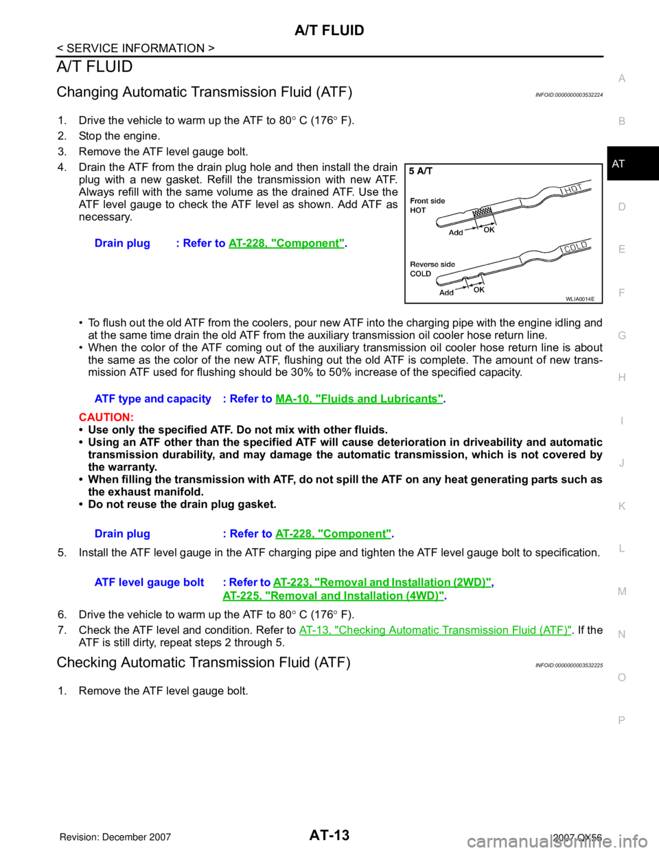
4. Drain the ATF from the drain plug hole and then install the drain
plug with a new gasket. Refill the transmission with new ATF.
Always refill with the same volume as the drained ATF. Use the
ATF level gauge to check the ATF level as shown. Add ATF as
necessary.
• To flush out the old ATF from the coolers, pour new ATF into the charging pipe with the engine idling and
at the same time drain the old ATF from the auxiliary transmission oil cooler hose return line.
• When the color of the ATF coming out of the auxiliary transmission oil cooler hose return line is about
the same as the color of the new ATF, flushing out the old ATF is complete. The amount of new trans-
mission ATF used for flushing should be 30% to 50% increase of the specified capacity.
CAUTION:
• Use only the specified ATF. Do not mix with other fluids.
• Using an ATF other than the specified ATF will cause deterioration in driveability and automatic
transmission durability, and may damage the automatic transmission, which is not covered by
the warranty.
• When filling the transmission with ATF, do not spill the ATF on any heat generating parts such as
the exhaust manifold.
• Do not reuse the drain plug gasket.
5. Install the ATF level gauge in the ATF charging pipe and tighten the ATF level gauge bolt to specification.
6. Drive the vehicle to warm up the ATF to 80° C (176° F).
7. Check the ATF level and condition. Refer to AT-13, "
Checking Automatic Transmission Fluid (ATF)". If the
ATF is still dirty, repeat steps 2 through 5.
Checking Automatic Transmission Fluid (ATF)INFOID:0000000003532225
1. Remove the ATF level gauge bolt.Drain plug : Refer to AT-228, "
Component".
WLIA0014E
ATF type and capacity : Refer to MA-10, "Fluids and Lubricants".
Drain plug : Refer to AT-228, "
Component".
ATF level gauge bolt : Refer to AT-223, "
Removal and Installation (2WD)",
AT-225, "
Removal and Installation (4WD)".
Page 368 of 3061
AT-298
< SERVICE INFORMATION >
SERVICE DATA AND SPECIFICATIONS (SDS)
SERVICE DATA AND SPECIFICATIONS (SDS)
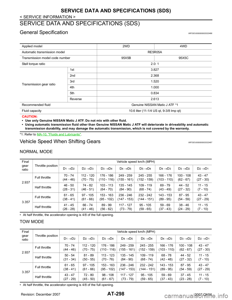
General SpecificationINFOID:0000000003532496
*1: Refer to MA-10, "Fluids and Lubricants".
Vehicle Speed When Shifting GearsINFOID:0000000003532497
NORMAL MODE
• At half throttle, the accelerator opening is 4/8 of the full opening.
TOW MODE
• At half throttle, the accelerator opening is 4/8 of the full opening.Applied model 2WD 4WD
Automatic transmission model RE5R05A
Transmission model code number 95X5B 95X5C
Stall torque ratio2.0: 1
Transmission gear ratio1st 3.827
2nd 2.368
3rd 1.520
4th 1.000
5th 0.834
Reverse 2.613
Recommended fluid Genuine NISSAN Matic J ATF *1
Fluid capacity 10.6 liter (11-1/4 US qt, 9-3/8 Imp qt)
CAUTION:
• Use only Genuine NISSAN Matic J ATF. Do not mix with other fluid.
• Using automatic transmission fluid other than Genuine NISSAN Matic J ATF will deteriorate in driveability and automatic
transmission durability, and may damage the automatic transmission, which is not covered by the warranty.
Final
gear
ratioThrottle positionVehicle speed km/h (MPH)
D
1 →D2D2 →D3D3 →D4D4 →D5D5 →D4D4 →D3D3 →D2D2 →D1
2.937Full throttle 70 - 74
(44 - 46)112 - 120
(70 - 75)176 - 186
(110 - 116)249 - 259
(155 - 161)245 - 255
(152 - 159)166 - 176
(103 - 110)100 - 108
(62 - 67)43 - 47
(27 - 30)
Half throttle 46 - 50
(28 - 31)74 - 82
(46 - 51)103 - 113
(64 - 70)135 - 145
(84 - 90)109 - 119
(68 - 74)69 - 79
(43 - 49)44 - 52
(27 - 32)11 - 1 5
(7 - 10)
3.357Full throttle 61 - 65
(38 - 41)97 - 105
(61 - 66)153 - 163
(95 - 102)236 - 246
(147 - 153)232 - 242
(144 - 151)143 - 153
(89 - 95)87 - 95
(54 - 59)43 - 47
(27 - 29)
Half throttle 41 - 45
(26 - 28)66 - 74
(41 - 46)89 - 99
(56 - 62)117 - 127
(73 - 79)95 - 105
(59 - 65)59 - 69
(37 - 43)38 - 46
(24 - 29)11 - 1 5
(7 - 10)
Final
gear
ratioThrottle positionVehicle speed km/h (MPH)
D
1 →D2D2 →D3D3 →D4D4 →D5D5 →D4D4 →D3D3 →D2D2 →D1
2.937Full throttle 70 - 74
(44 - 46)112 - 120
(70 - 75)176 - 186
(110 - 116)249 - 259
(155 - 161)245 - 255
(152 - 159)166 - 176
(103 - 110)100 - 108
(62 - 67)43 - 47
(27 - 30)
Half throttle 50 - 54
(31 - 34)81 - 89
(50 - 55)113 - 123
(70 - 76)135 - 145
(84 - 90)109 - 119
(68 - 74)68 - 78
(42 - 48)44 - 52
(27 - 32)11 - 1 5
(7 - 10)
3.357Full throttle 61 - 65
(38 - 41)97 - 105
(61 - 66)153 - 163
(95 - 102)236 - 246
(147 - 153)232 - 242
(144 - 151)143 - 153
(89 - 95)87 - 95
(54 - 59)43 - 47
(27 - 29)
Half throttle 43 - 47
(27 - 29)72 - 80
(45 - 50)98 - 108
(61 - 67)117 - 127
(73 - 79)95 - 105
(59 - 65)59 - 69
(37 - 43)37 - 45
(23 - 28)11 - 1 5
(7 - 10)
Page 1000 of 3061
ENGINE COOLANT
CO-11
< SERVICE INFORMATION >
C
D
E
F
G
H
I
J
K
L
MA
CO
N
P O
3. Remove the vented reservoir cap and replace it with a non-vented reservoir cap before filling the cooling
system.
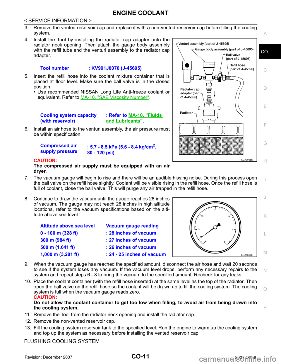
4. Install the Tool by installing the radiator cap adapter onto the
radiator neck opening. Then attach the gauge body assembly
with the refill tube and the venturi assembly to the radiator cap
adapter.
5. Insert the refill hose into the coolant mixture container that is
placed at floor level. Make sure the ball valve is in the closed
position.
• Use recommended NISSAN Long Life Anti-freeze coolant or
equivalent. Refer to MA-10, "
SAE Viscosity Number".
6. Install an air hose to the venturi assembly, the air pressure must
be within specification.
CAUTION:
The compressed air supply must be equipped with an air
dryer.
7. The vacuum gauge will begin to rise and there will be an audible hissing noise. During this process open
the ball valve on the refill hose slightly. Coolant will be visible rising in the refill hose. Once the refill hose is
full of coolant, close the ball valve. This will purge any air trapped in the refill hose.
8. Continue to draw the vacuum until the gauge reaches 28 inches
of vacuum. The gauge may not reach 28 inches in high altitude
locations, refer to the vacuum specifications based on the alti-
tude above sea level.
9. When the vacuum gauge has reached the specified amount, disconnect the air hose and wait 20 seconds
to see if the system loses any vacuum. If the vacuum level drops, perform any necessary repairs to the
system and repeat steps 6 - 8 to bring the vacuum to the specified amount. Recheck for any leaks.
10. Place the coolant container (with the refill hose inserted) at the same level as the top of the radiator. Then
open the ball valve on the refill hose so the coolant will be drawn up to fill the cooling system. The cooling
system is full when the vacuum gauge reads zero.
CAUTION:
Do not allow the coolant container to get too low when filling, to avoid air from being drawn into
the cooling system.
11. Remove the Tool from the radiator neck opening and install the radiator cap.
12. Remove the non-vented reservoir cap.
13. Fill the cooling system reservoir tank to the specified level. Run the engine to warm up the cooling system
and top up the system as necessary before installing the vented reservoir cap.
FLUSHING COOLING SYSTEM
Tool number : KV991J0070 (J-45695)
Cooling system capacity
(with reservoir): Refer to MA-10, "
Fluids
and Lubricants".
Compressed air
supply pressure: 5.7 - 8.5 kPa (5.6 - 8.4 kg/cm
2,
80 - 120 psi)
LLIA0058E
Altitude above sea level Vacuum gauge reading
0 - 100 m (328 ft) : 28 inches of vacuum
300 m (984 ft) : 27 inches of vacuum
500 m (1,641 ft) : 26 inches of vacuum
1,000 m (3,281 ft) : 24 - 25 inches of vacuum
LLIA0057E
Page 1846 of 3061
EM-76
< SERVICE INFORMATION >
ENGINE ASSEMBLY
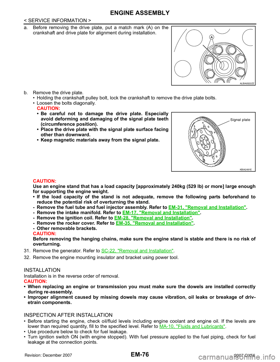
a. Before removing the drive plate, put a match mark (A) on the
crankshaft and drive plate for alignment during installation.
b. Remove the drive plate.
• Holding the crankshaft pulley bolt, lock the crankshaft to remove the drive plate bolts.
• Loosen the bolts diagonally.
CAUTION:
• Be careful not to damage the drive plate. Especially
avoid deforming and damaging of the signal plate teeth
(circumference position).
• Place the drive plate with the signal plate surface facing
other than downward.
• Keep magnetic materials away from the signal plate.
CAUTION:
Use an engine stand that has a load capacity [approximately 240kg (529 lb) or more] large enough
for supporting the engine weight.
• If the load capacity of the stand is not adequate, remove the following parts beforehand to
reduce the potential risk of overturning the stand.
- Remove the fuel tube and fuel injector assembly. Refer to EM-31, "
Removal and Installation".
- Remove the intake manifold. Refer to EM-17, "
Removal and Installation".
- Remove the ignition coil. Refer to EM-28, "
Removal and Installation".
- Remove the rocker cover. Refer to EM-35, "
Removal and Installation".
- Other removable brackets.
CAUTION:
Before removing the hanging chains, make sure the engine stand is stable and there is no risk of
overturning.
31. Remove the generator. Refer to SC-22, "
Removal and Installation".
32. Remove the engine mounting insulator and bracket using power tool.
INSTALLATION
Installation is in the reverse order of removal.
CAUTION:
• When replacing an engine or transmission you must make sure the dowels are installed correctly
during re-assembly.
• Improper alignment caused by missing dowels may cause vibration, oil leaks or breakage of driv-
etrain components.
INSPECTION AFTER INSTALLATION
• Before starting the engine, check oil/fluid levels including engine coolant and engine oil. If the levels are
lower than required quantity, fill to the specified level. Refer to MA-10, "
Fluids and Lubricants".
• Use procedure below to check for fuel leakage.
• Turn ignition switch ON (with engine stopped). With fuel pressure applied to the fuel piping, check for fuel
leakage at the connection points.
ALBIA0522ZZ
KBIA2491E
Page 1847 of 3061
ENGINE ASSEMBLY
EM-77
< SERVICE INFORMATION >
C
D
E
F
G
H
I
J
K
L
MA
EM
N
P O
• Start engine. With engine speed increased, check again for fuel leakage at connection points.
• Run engine to check for unusual noise and vibration.
• Warm up engine thoroughly to make sure there is no leakage of fuel, exhaust gas, or any oils/fluids including
engine oil and engine coolant.
• Bleed air from passages in lines and hoses, such as in cooling system.
• After cooling down the engine, again check oil/fluid levels including engine oil and engine coolant. Refill to
specified level if necessary.
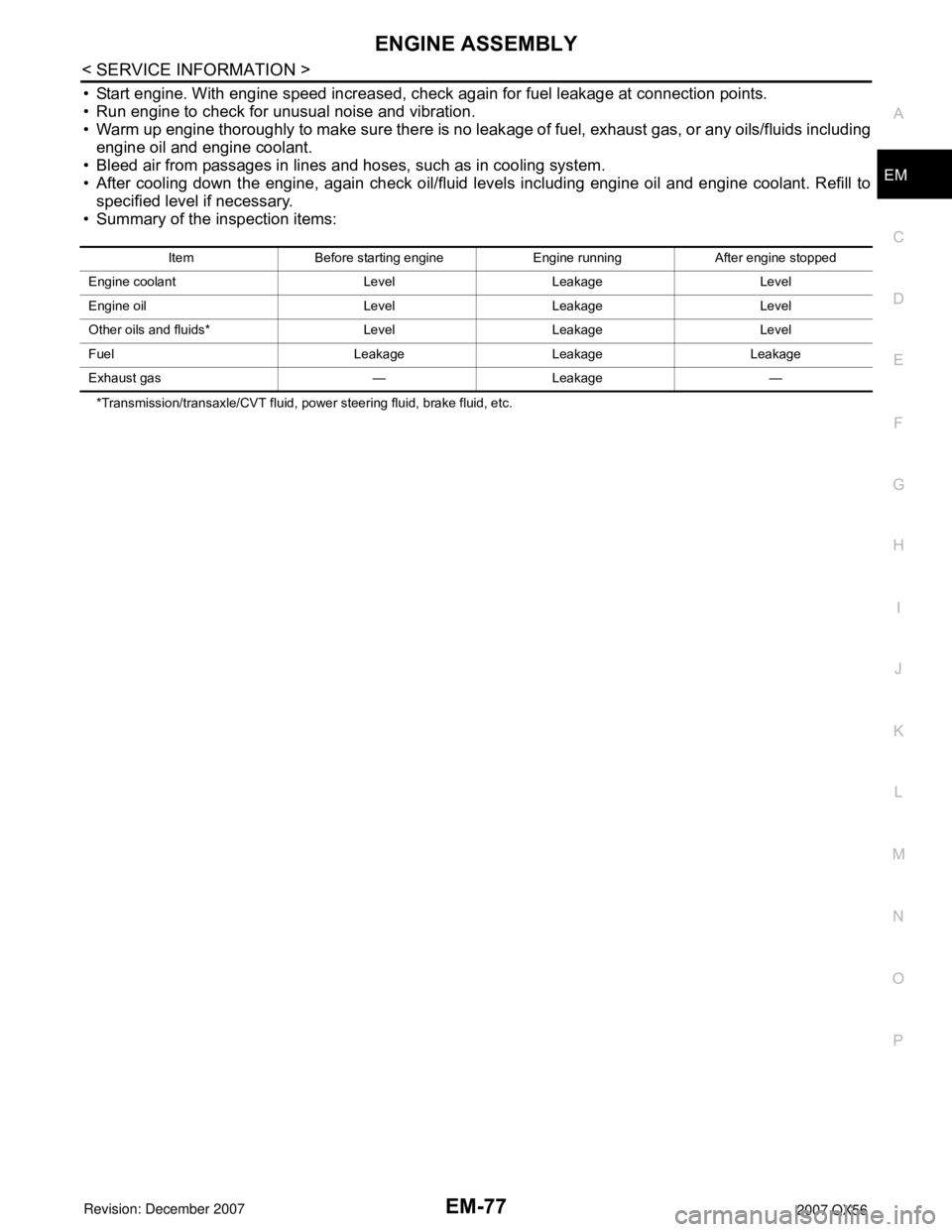
• Summary of the inspection items:
*Transmission/transaxle/CVT fluid, power steering fluid, brake fluid, etc.Item Before starting engine Engine running After engine stopped
Engine coolant Level Leakage Level
Engine oil Level Leakage Level
Other oils and fluids* Level Leakage Level
Fuel Leakage Leakage Leakage
Exhaust gas — Leakage —
Page 1906 of 3061
DIFFERENTIAL GEAR OIL
FFD-7
< SERVICE INFORMATION >
C
E
F
G
H
I
J
K
L
MA
B
FFD
N
O
P
DIFFERENTIAL GEAR OIL
Changing Differential Gear OilINFOID:0000000003532588
DRAINING
1. Stop the engine.
2. Remove the drain plug from the front final drive assembly to drain the differential gear oil.
3. Install the drain plug with sealant applied on the threads to the front final drive assembly. Tighten to the
specified torque. Refer to FFD-13, "
Disassembly and Assembly".
• Use High Performance Thread Sealant or equivalent. Refer to GI-45, "
Recommended Chemical Product
and Sealant".
FILLING
1. Remove the filler plug from the front final drive assembly.
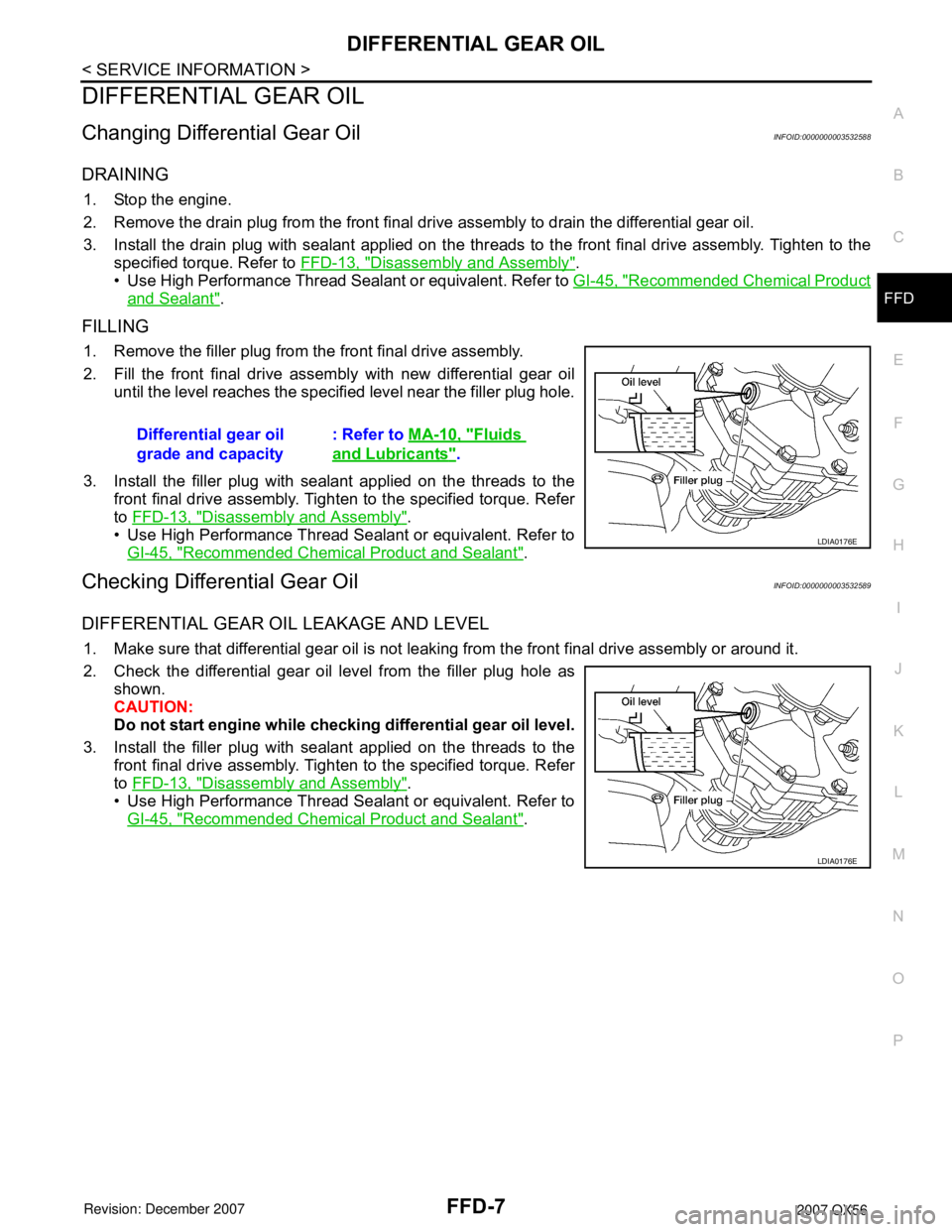
2. Fill the front final drive assembly with new differential gear oil
until the level reaches the specified level near the filler plug hole.
3. Install the filler plug with sealant applied on the threads to the
front final drive assembly. Tighten to the specified torque. Refer
to FFD-13, "
Disassembly and Assembly".
• Use High Performance Thread Sealant or equivalent. Refer to
GI-45, "
Recommended Chemical Product and Sealant".
Checking Differential Gear OilINFOID:0000000003532589
DIFFERENTIAL GEAR OIL LEAKAGE AND LEVEL
1. Make sure that differential gear oil is not leaking from the front final drive assembly or around it.
2. Check the differential gear oil level from the filler plug hole as
shown.
CAUTION:
Do not start engine while checking differential gear oil level.
3. Install the filler plug with sealant applied on the threads to the
front final drive assembly. Tighten to the specified torque. Refer
to FFD-13, "
Disassembly and Assembly".
• Use High Performance Thread Sealant or equivalent. Refer to
GI-45, "
Recommended Chemical Product and Sealant". Differential gear oil
grade and capacity: Refer to MA-10, "
Fluids
and Lubricants".
LDIA0176E
LDIA0176E
Page 1969 of 3061
PRECAUTIONS
GI-3
< SERVICE INFORMATION >
C
D
E
F
G
H
I
J
K
L
MB
GI
N
O
P
General PrecautionINFOID:0000000003531471
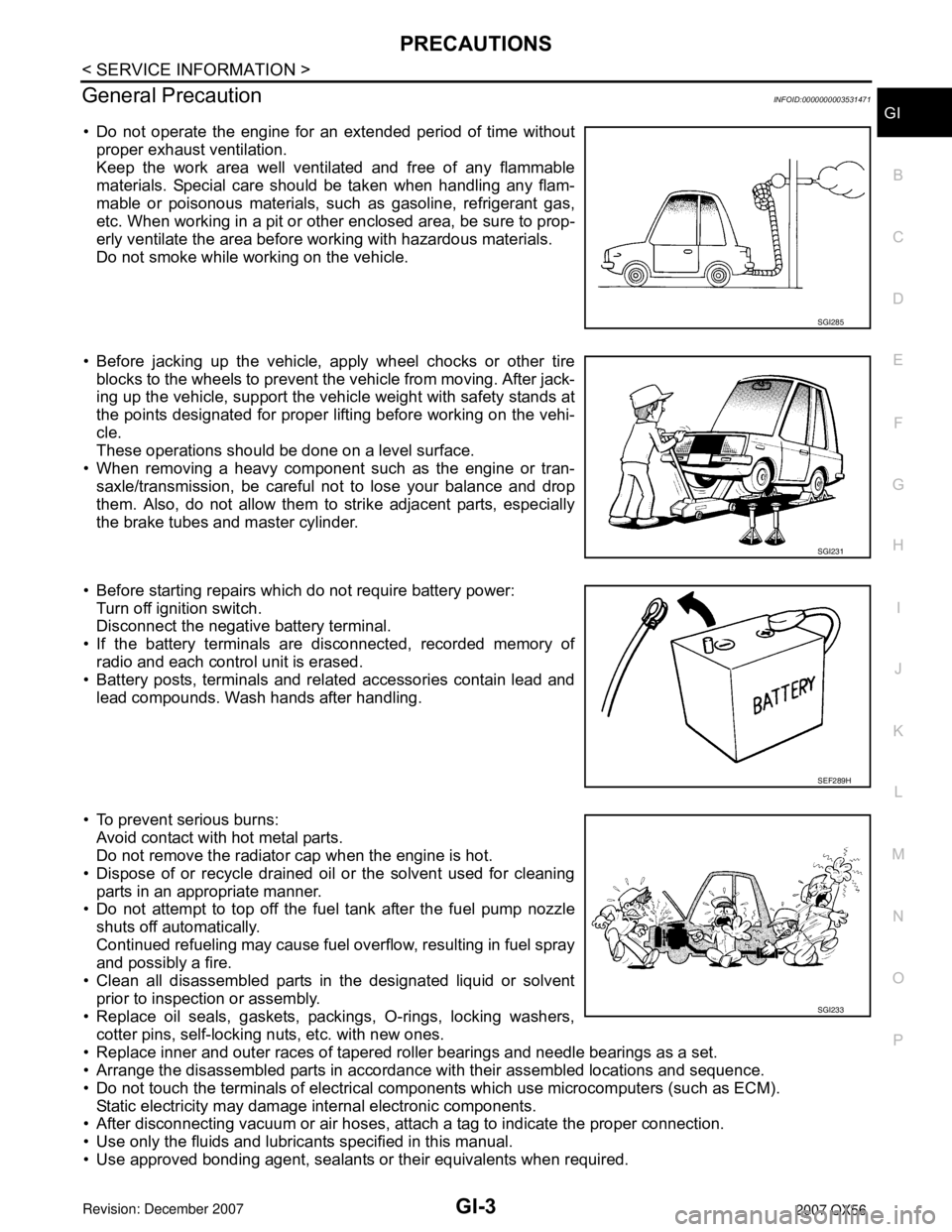
• Do not operate the engine for an extended period of time without
proper exhaust ventilation.
Keep the work area well ventilated and free of any flammable
materials. Special care should be taken when handling any flam-
mable or poisonous materials, such as gasoline, refrigerant gas,
etc. When working in a pit or other enclosed area, be sure to prop-
erly ventilate the area before working with hazardous materials.
Do not smoke while working on the vehicle.
• Before jacking up the vehicle, apply wheel chocks or other tire
blocks to the wheels to prevent the vehicle from moving. After jack-
ing up the vehicle, support the vehicle weight with safety stands at
the points designated for proper lifting before working on the vehi-
cle.
These operations should be done on a level surface.
• When removing a heavy component such as the engine or tran-
saxle/transmission, be careful not to lose your balance and drop
them. Also, do not allow them to strike adjacent parts, especially
the brake tubes and master cylinder.
• Before starting repairs which do not require battery power:
Turn off ignition switch.
Disconnect the negative battery terminal.
• If the battery terminals are disconnected, recorded memory of
radio and each control unit is erased.
• Battery posts, terminals and related accessories contain lead and
lead compounds. Wash hands after handling.
• To prevent serious burns:
Avoid contact with hot metal parts.
Do not remove the radiator cap when the engine is hot.
• Dispose of or recycle drained oil or the solvent used for cleaning
parts in an appropriate manner.
• Do not attempt to top off the fuel tank after the fuel pump nozzle
shuts off automatically.
Continued refueling may cause fuel overflow, resulting in fuel spray
and possibly a fire.
• Clean all disassembled parts in the designated liquid or solvent
prior to inspection or assembly.
• Replace oil seals, gaskets, packings, O-rings, locking washers,
cotter pins, self-locking nuts, etc. with new ones.
• Replace inner and outer races of tapered roller bearings and needle bearings as a set.
• Arrange the disassembled parts in accordance with their assembled locations and sequence.
• Do not touch the terminals of electrical components which use microcomputers (such as ECM).
Static electricity may damage internal electronic components.
• After disconnecting vacuum or air hoses, attach a tag to indicate the proper connection.
• Use only the fluids and lubricants specified in this manual.
• Use approved bonding agent, sealants or their equivalents when required.
SGI285
SGI231
SEF289H
SGI233
Page 2108 of 3061
IDX-4
ALPHABETICAL INDEX
Duct and grilles .............................................. ATC-170
DVD - Wiring Diagram ....................................... AV-75
DVD Entertainment System ............................... AV-72
DVD Player ........................................................ AV-73
E
ECM input/output signal ..................... EC-109
, EC-133
ECM power supply ............................. EC-150, EC-475
ECM relay ........................................................ EC-150
ECM/PW - Wiring diagram ............................... EC-476
ECTS - Wiring diagram .................................... EC-220
Electric sunroof .................................................. RF-10
Electric throttle control actuator ......... EC-595, EC-606
Electrical load signal circuit .............................. EC-657
Electrical units location ...................................... PG-65
Electronic ignition (EI) system ........................... EC-27
Engine control circuit diagram ......................... EC-107
Engine control component parts location ........... EC-98
Engine control module (ECM) .......................... EC-479
Engine control system diagram ......................... EC-24
Engine coolant .................................................. CO-10
Engine coolant temperature sensor (ECTS) ... EC-218,
EC-231
Engine fail-safe system ...................................... EC-93
Engine oil ............................................................. LU-8
Engine oil filter replacement ............................. MA-17
Engine oil precautions .......................................... GI-7
Engine oil replacement ..................................... MA-17
Engine removal ................................................. EM-74
Engine room cover ............................................ EM-12
Engine serial number .......................................... GI-50
ETC1 - Wiring diagram .................................... EC-596
ETC2 - Wiring diagram .................................... EC-591
ETC3 - Wiring diagram .................................... EC-602
EVAP canister .................................................... EC-36
EVAP canister purge volume control solenoid valve ....
EC-395
, EC-403
EVAP canister vent control valve ....... EC-410, EC-417
EVAP control system (small leak) diagnosis .. EC-387,
EC-441
, EC-449
EVAP control system pressure sensor .... EC-424, EC-
427, EC-433
EVAP control system purge flow monitoring diagnosis
EC-382
EVAP vapor lines inspection ............................. MA-20
Evaporative emission (EVAP) system ............... EC-33
Evaporator ..................................................... ATC-186
Exhaust manifold .............................................. EM-21
Exhaust system ................................................... EX-3
Exhaust system inspection .................................. EX-3
Expansion valve ............................................. ATC-188
F
F/FOG - Wiring diagram ..................................... LT-56
F/PUMP - Wiring diagram ................................ EC-666
Final drive pre-inspection ................................. FFD-15
Final drive removal and installation .. FFD-12, RFD-13
Flow charts .......................................................... GI-27
Fluid temperature sensor (A/T) ........................ AT-123
Fluids ................................................................ MA-11
Fluorescent leak detector .............................. ATC-189
Fog lamp, front ................................................... LT-54
Fog lamp, front, removal and installation ........... LT-62
Foot lamp ......................................................... LT-111
Freeze frame data ............................... EC-55, EC-121
Front brake solenoid valve ................. AT-139, AT-141
Front bumper ...................................................... EI-13
Front case (Transfer) .......................... TF-149, TF-176
Front combination lamp removal and installation LT-25
Front door ............................. BL-117, BL-121, GW-62
Front Door Trim ................................................... EI-32
Front drive shaft (Transfer) ................. TF-149, TF-176
Front fog lamp .................................................... LT-54
Front fog lamp removal and installation ............. LT-62
Front passenger air bag .................................. SRS-43
Front seat ........................................................... SE-89
Front seat belt ...................................................... SB-3
Front seat belt pre-tensioner ............... SRS-3, SRS-50
Front washer ...................................................... WW-4
Front wiper ......................................................... WW-4
FTS - Wiring diagram ....................................... AT-124
FTTS - Wiring diagram ...................... EC-334, EC-339
Fuel cut control (at no load high engine speed) EC-28
Fuel filter replacement ......................................... FL-5
Fuel gauge ............................................................ DI-5
Fuel injection system (Bank 1) .......... EC-311, EC-322
Fuel injection system (Bank 2) .......... EC-311, EC-322
Fuel injector .................................................... EC-659
Fuel injector and fuel tube ................................. EM-31
Fuel level sensor ................. EC-458, EC-460, EC-462
Fuel line inspection .............................................. FL-4
Fuel precautions ................................................... GI-5
Fuel pressure check .......................................... EC-82
Fuel pressure release ....................................... EC-82
Fuel pump ....................................................... EC-665
Fuel pump and gauge .......................................... FL-5
Fuel system .......................................................... FL-4
Fuel tank ............................................................ FL-10
Fuel tank temperature sensor ........... EC-332, EC-338
Fuel tank vacuum relief valve ........................... EC-36
FUELB1 - Wiring diagram ................. EC-313, EC-324
FUELB2 - Wiring diagram ................. EC-315, EC-326
Fuse ...................................................... PG-17, PG-77
Fuse and fusible link box .................................. PG-77
Fuse block ......................................................... PG-76
Fusible link ............................................ PG-17, PG-77
G
Garage jack and safety stand ............................. GI-42
Gauges ................................................................. DI-5
Generator .......................................................... SC-17
Generic scan tool (GST) ................................. EC-131
Glass ...................................... GW-11, GW-62, GW-65
Glove box lamp ................................................ LT-131
GPS antenna ..................................................... AV-82
Page 2354 of 3061
ENGINE OIL
LU-9
< SERVICE INFORMATION >
C
D
E
F
G
H
I
J
K
L
MA
LU
N
P O
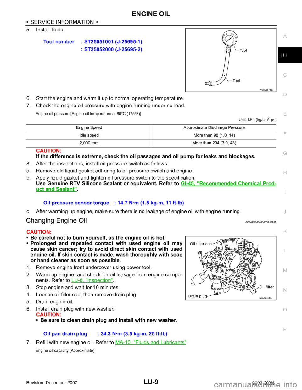
5. Install Tools.
6. Start the engine and warm it up to normal operating temperature.
7. Check the engine oil pressure with engine running under no-load.
Engine oil pressure [Engine oil temperature at 80°C (175°F)]
Unit: kPa (kg/cm2
, psi)
CAUTION:
If the difference is extreme, check the oil passages and oil pump for leaks and blockages.
8. After the inspections, install oil pressure switch as follows:
a. Remove old liquid gasket adhering to oil pressure switch and engine.
b. Apply liquid gasket and tighten oil pressure switch to the specification.
Use Genuine RTV Silicone Sealant or equivalent. Refer to GI-45, "
Recommended Chemical Prod-
uct and Sealant".
c. After warming up engine, make sure there is no leakage of engine oil with engine running.
Changing Engine OilINFOID:0000000003531556
CAUTION:
• Be careful not to burn yourself, as the engine oil is hot.
• Prolonged and repeated contact with used engine oil may
cause skin cancer; try to avoid direct skin contact with used
engine oil. If skin contact is made, wash thoroughly with soap
or hand cleaner as soon as possible.
1. Remove engine front undercover using power tool.
2. Warm up engine, and check for oil leakage from engine compo-
nents. Refer to LU-8, "
Inspection".
3. Stop engine and wait for 10 minutes.
4. Loosen oil filler cap, then remove drain plug.
5. Drain engine oil.
6. Install drain plug with new washer.
CAUTION:
• Be sure to clean drain plug and install with new washer.
7. Refill with new engine oil. Refer to MA-10, "
Fluids and Lubricants".
Engine oil capacity (Approximate):
Tool number : ST25051001 (J-25695-1)
: ST25052000 (J-25695-2)
WBIA0571E
Engine Speed Approximate Discharge Pressure
Idle speed More than 98 (1.0, 14)
2,000 rpm More than 294 (3.0, 43)
Oil pressure sensor torque : 14.7 N·m (1.5 kg-m, 11 ft-lb)
Oil pan drain plug : 34.3 N·m (3.5 kg-m, 25 ft-lb)
KBIA2498E
Page 2363 of 3061
MA-1
MAINTENANCE
C
D
E
F
G
H
I
J
K
M
SECTION MA
A
B
MA
N
O
P
CONTENTS
MAINTENANCE
SERVICE INFORMATION ............................2
PRECAUTIONS ...................................................2
Precaution for Supplemental Restraint System
(SRS) "AIR BAG" and "SEAT BELT PRE-TEN-
SIONER" ...................................................................
2
PREPARATION ...................................................3
Special Service Tool .................................................3
Commercial Service Tool ..........................................3
GENERAL MAINTENANCE ................................4
General Maintenance ................................................4
PERIODIC MAINTENANCE ................................6
Introduction of Periodic Maintenance ........................6
Maintenance for Off-road Driving (4WD only) ...........6
Schedule 1 ................................................................6
Schedule 2 ................................................................8
RECOMMENDED FLUIDS AND LUBRI-
CANTS ................................................................
10
Fluids and Lubricants ..............................................10
SAE Viscosity Number ............................................10
ENGINE MAINTENANCE ...................................12
Checking Drive Belts ...............................................12
Changing Engine Coolant .......................................12
Checking Fuel Line .................................................15
Changing Fuel Filter ................................................15
Changing Engine Air Cleaner Filter .........................15
Changing Engine Oil ................................................16
Changing Oil Filter ...................................................16
Changing Spark Plugs .............................................18
Checking EVAP Vapor Line .....................................19
CHASSIS AND BODY MAINTENANCE ...........20
Changing In-cabin Microfilter ...................................20
Checking Exhaust System .......................................21
Checking Automatic Transmission Fluid (ATF) .......21
Changing Automatic Transmission Fluid (ATF) .......23
Changing Transfer Fluid ..........................................23
Checking Transfer Fluid ..........................................24
Checking Propeller Shaft .........................................24
Checking Final Drive Oil ..........................................24
Changing Final Drive Oil ..........................................25
Balancing Wheels ....................................................25
Tire Rotation ............................................................27
Checking Brake Fluid Level and Leaks ...................27
CheckingBrake Line and Cables .............................27
Checking Disc Brake ...............................................27
Checking Steering Gear and Linkage ......................28
Checking Power Steering Fluid and Line ................28
Checking Axle and Suspension Parts .....................29
Lubricating Locks, Hinges and Hood Latches .........30
Checking Seat Belts, Buckles, Retractors, An-
chors and Adjusters .................................................
30