ESP INFINITI QX56 2007 Factory Owners Manual
[x] Cancel search | Manufacturer: INFINITI, Model Year: 2007, Model line: QX56, Model: INFINITI QX56 2007Pages: 3061, PDF Size: 64.56 MB
Page 2116 of 3061

IP-4
< SERVICE INFORMATION >
SQUEAK AND RATTLE TROUBLE DIAGNOSIS
SQUEAK AND RATTLE TROUBLE DIAGNOSIS
Work FlowINFOID:0000000003533144
CUSTOMER INTERVIEW
Interview the customer, if possible, to determine the conditions that exist when the noise occurs. Use the Diag-
nostic Worksheet during the interview to document the facts and conditions when the noise occurs and any
customer's comments; refer to IP-8, "
Diagnostic Worksheet". This information is necessary to duplicate the
conditions that exist when the noise occurs.
• The customer may not be able to provide a detailed description or the location of the noise. Attempt to obtain
all the facts and conditions that exist when the noise occurs (or does not occur).
• If there is more than one noise in the vehicle, be sure to diagnose and repair the noise that the customer is
concerned about. This can be accomplished by test driving the vehicle with the customer.
• After identifying the type of noise, isolate the noise in terms of its characteristics. The noise characteristics
are provided so the customer, service adviser and technician are all speaking the same language when
defining the noise.
- Squeak — (Like tennis shoes on a clean floor)
Squeak characteristics include the light contact/fast movement/brought on by road conditions/hard surfaces
= higher pitch noise/softer surfaces = lower pitch noises/edge to surface = chirping.
- Creak — (Like walking on an old wooden floor)
Creak characteristics include firm contact/slow movement/twisting with a rotational movement/pitch depen-
dent on materials/often brought on by activity.
- Rattle — (Like shaking a baby rattle)
Rattle characteristics include the fast repeated contact/vibration or similar movement/loose parts/missing
clip or fastener/incorrect clearance.
- Knock — (Like a knock on a door)
Knock characteristics include hollow sounding/sometimes repeating/often brought on by driver action.
- Tick — (Like a clock second hand)
Tick characteristics include gentle contacting of light materials/loose components/can be caused by driver
action or road conditions.
- Thump — (Heavy, muffled knock noise)
Thump characteristics include softer knock/dead sound often brought on by activity.
- Buzz — (Like a bumblebee)
Buzz characteristics include high frequency rattle/firm contact.
• Often the degree of acceptable noise level will vary depending upon the person. A noise that you may judge
as acceptable may be very irritating to the customer.
• Weather conditions, especially humidity and temperature, may have a great effect on noise level.
DUPLICATE THE NOISE AND TEST DRIVE
If possible, drive the vehicle with the customer until the noise is duplicated. Note any additional information on
the Diagnostic Worksheet regarding the conditions or location of the noise. This information can be used to
duplicate the same conditions when you confirm the repair.
SBT842
Page 2212 of 3061

HEADLAMP (FOR USA)
LT-5
< SERVICE INFORMATION >
C
D
E
F
G
H
I
J
L
MA
B
LT
N
O
P
HEADLAMP (FOR USA)
Component Parts and Harness Connector LocationINFOID:0000000003533332
System DescriptionINFOID:0000000003533333
Control of the headlamp system operation is dependent upon the position of the combination switch (lighting
switch). When the lighting switch is placed in the 2ND position, the BCM (body control module) receives input
requesting the headlamps (and tail lamps) illuminate. This input is communicated to the IPDM E/R (intelligent
power distribution module engine room) across the CAN communication lines. The CPU (central processing
unit) of the IPDM E/R controls the headlamp high and headlamp low relay coils. When energized, these relays
direct power to the respective headlamps, which then illuminate.
OUTLINE
Power is supplied at all times
• to ignition relay, located in the IPDM E/R,
• to headlamp high relay, located in the IPDM E/R,
• to headlamp low relay, located in the IPDM E/R,
• through 20A fuse (No. 53, located in the IPDM E/R)
• to CPU of the IPDM E/R, and
• through 50A fusible link (letter f , located in the fuse and fusible link box)
• to BCM terminal 70.
With the ignition switch in the ON or START position, power is supplied
• to ignition relay, located in the IPDM E/R, and
• through 10A fuse (No. 59, located in the fuse and relay box)
WKIA3463E
Page 2281 of 3061

LT-74
< SERVICE INFORMATION >
COMBINATION SWITCH
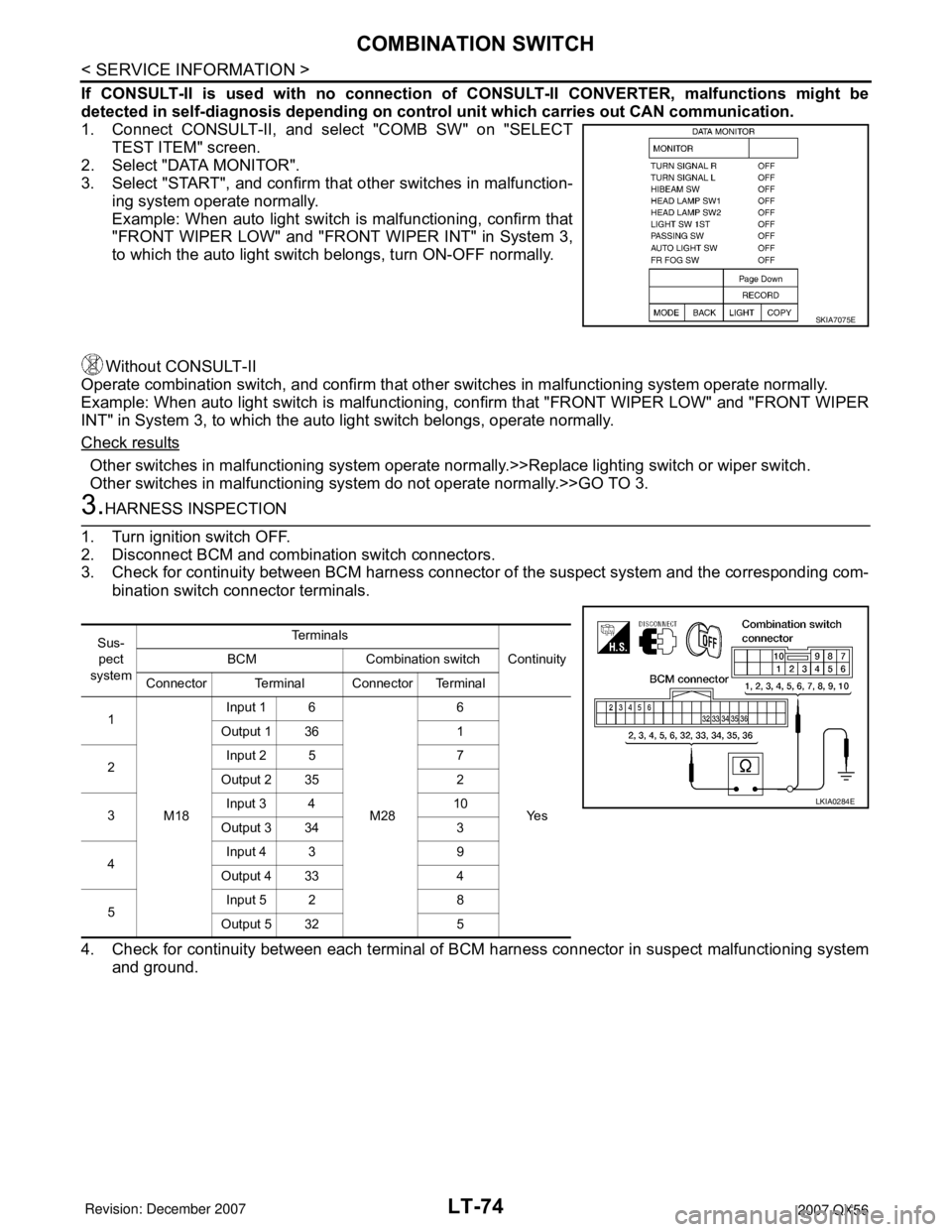
If CONSULT-II is used with no connection of CONSULT-II CONVERTER, malfunctions might be
detected in self-diagnosis depending on control unit which carries out CAN communication.
1. Connect CONSULT-II, and select "COMB SW" on "SELECT
TEST ITEM" screen.
2. Select "DATA MONITOR".
3. Select "START", and confirm that other switches in malfunction-
ing system operate normally.
Example: When auto light switch is malfunctioning, confirm that
"FRONT WIPER LOW" and "FRONT WIPER INT" in System 3,
to which the auto light switch belongs, turn ON-OFF normally.
Without CONSULT-II
Operate combination switch, and confirm that other switches in malfunctioning system operate normally.
Example: When auto light switch is malfunctioning, confirm that "FRONT WIPER LOW" and "FRONT WIPER
INT" in System 3, to which the auto light switch belongs, operate normally.
Check results
Other switches in malfunctioning system operate normally.>>Replace lighting switch or wiper switch.
Other switches in malfunctioning system do not operate normally.>>GO TO 3.
3.HARNESS INSPECTION
1. Turn ignition switch OFF.
2. Disconnect BCM and combination switch connectors.
3. Check for continuity between BCM harness connector of the suspect system and the corresponding com-
bination switch connector terminals.
4. Check for continuity between each terminal of BCM harness connector in suspect malfunctioning system
and ground.
SKIA7075E
Sus-
pect
systemTe r m i n a l s
Continuity BCM Combination switch
Connector Terminal Connector Terminal
1
M18Input 1 6
M286
Ye s Output 1 36 1
2Input 2 5 7
Output 2 35 2
3Input 3 4 10
Output 3 34 3
4Input 4 3 9
Output 4 33 4
5Input 5 2 8
Output 5 32 5
LKIA0284E
Page 2468 of 3061

PG-66
< SERVICE INFORMATION >
HARNESS CONNECTOR
HARNESS CONNECTOR
DescriptionINFOID:0000000003533849
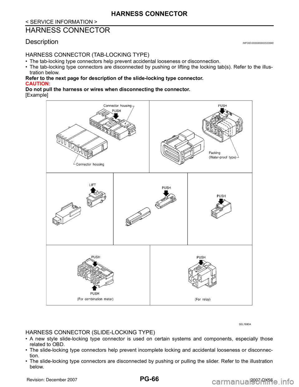
HARNESS CONNECTOR (TAB-LOCKING TYPE)
• The tab-locking type connectors help prevent accidental looseness or disconnection.
• The tab-locking type connectors are disconnected by pushing or lifting the locking tab(s). Refer to the illus-
tration below.
Refer to the next page for description of the slide-locking type connector.
CAUTION:
Do not pull the harness or wires when disconnecting the connector.
[Example]
HARNESS CONNECTOR (SLIDE-LOCKING TYPE)
• A new style slide-locking type connector is used on certain systems and components, especially those
related to OBD.
• The slide-locking type connectors help prevent incomplete locking and accidental looseness or disconnec-
tion.
• The slide-locking type connectors are disconnected by pushing or pulling the slider. Refer to the illustration
below.
SEL769DA
Page 2536 of 3061

RF-4
< SERVICE INFORMATION >
SQUEAK AND RATTLE TROUBLE DIAGNOSIS
SQUEAK AND RATTLE TROUBLE DIAGNOSIS
Work FlowINFOID:0000000003533092
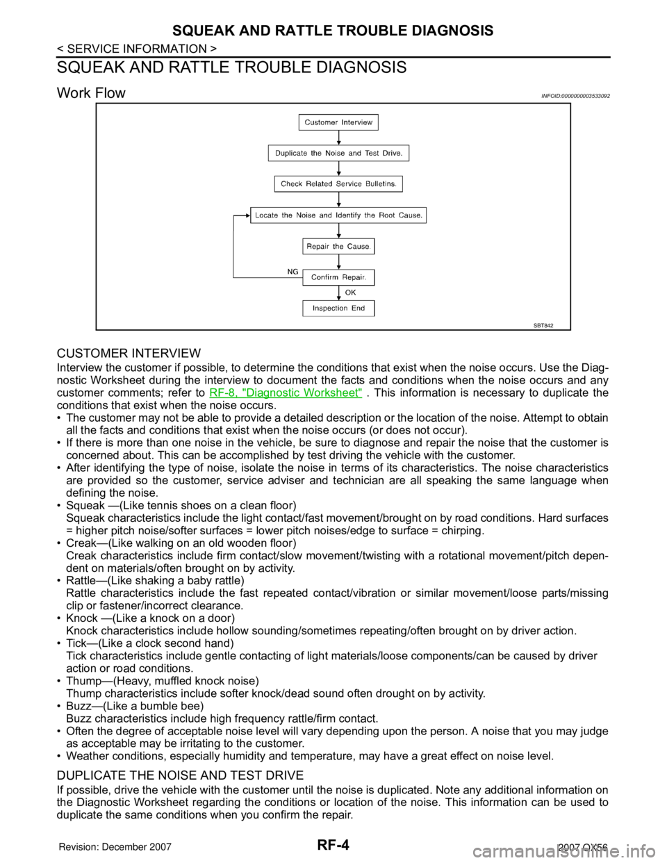
CUSTOMER INTERVIEW
Interview the customer if possible, to determine the conditions that exist when the noise occurs. Use the Diag-
nostic Worksheet during the interview to document the facts and conditions when the noise occurs and any
customer comments; refer to RF-8, "
Diagnostic Worksheet" . This information is necessary to duplicate the
conditions that exist when the noise occurs.
• The customer may not be able to provide a detailed description or the location of the noise. Attempt to obtain
all the facts and conditions that exist when the noise occurs (or does not occur).
• If there is more than one noise in the vehicle, be sure to diagnose and repair the noise that the customer is
concerned about. This can be accomplished by test driving the vehicle with the customer.
• After identifying the type of noise, isolate the noise in terms of its characteristics. The noise characteristics
are provided so the customer, service adviser and technician are all speaking the same language when
defining the noise.
• Squeak —(Like tennis shoes on a clean floor)
Squeak characteristics include the light contact/fast movement/brought on by road conditions. Hard surfaces
= higher pitch noise/softer surfaces = lower pitch noises/edge to surface = chirping.
• Creak—(Like walking on an old wooden floor)
Creak characteristics include firm contact/slow movement/twisting with a rotational movement/pitch depen-
dent on materials/often brought on by activity.
• Rattle—(Like shaking a baby rattle)
Rattle characteristics include the fast repeated contact/vibration or similar movement/loose parts/missing
clip or fastener/incorrect clearance.
• Knock —(Like a knock on a door)
Knock characteristics include hollow sounding/sometimes repeating/often brought on by driver action.
• Tick—(Like a clock second hand)
Tick characteristics include gentle contacting of light materials/loose components/can be caused by driver
action or road conditions.
• Thump—(Heavy, muffled knock noise)
Thump characteristics include softer knock/dead sound often drought on by activity.
• Buzz—(Like a bumble bee)
Buzz characteristics include high frequency rattle/firm contact.
• Often the degree of acceptable noise level will vary depending upon the person. A noise that you may judge
as acceptable may be irritating to the customer.
• Weather conditions, especially humidity and temperature, may have a great effect on noise level.
DUPLICATE THE NOISE AND TEST DRIVE
If possible, drive the vehicle with the customer until the noise is duplicated. Note any additional information on
the Diagnostic Worksheet regarding the conditions or location of the noise. This information can be used to
duplicate the same conditions when you confirm the repair.
SBT842
Page 2596 of 3061

RSU-6
< SERVICE INFORMATION >
TROUBLE DIAGNOSIS
TROUBLE DIAGNOSIS
How to Perform Trouble Diagnosis for Quick and Accurate RepairINFOID:0000000003532657
INTRODUCTION
The rear load leveling air suspension system uses an electronic con-
trol unit to control major functions. The control unit accepts input sig-
nals from the height sensor and controls compressor and exhaust
valve operation.
It is much more difficult to diagnose a rear load leveling air suspen-
sion system problem that occurs intermittently rather than continu-
ously. Most intermittent problems are caused by poor electrical
connections or faulty wiring. In this case, careful checking of suspi-
cious circuits may help prevent the replacement of good parts.
Before undertaking actual checks, take just a few minutes to talk with
a customer who approaches with an air suspension system com-
plaint. The customer is a very good source of information on such
problems, especially intermittent ones. Through discussion with the
customer, find out what symptoms are present and under what con-
ditions they occur.
Start your diagnosis by looking for basic mechanical problems first.
This is one of the best ways to troubleshoot concerns on an air sus-
pension system equipped vehicle. Also check related Service Bulle-
tins for information.
CLARIFY CONCERN
• A customer's description of a vehicle concern may vary depending
on the individual. It is important to clarify the customer's concern.
• Ask the customer about what symptoms are present under what
conditions. Use this information to reproduce the symptom.
SEF233G
SEF234G
SBR339B
Page 2677 of 3061

SQUEAK AND RATTLE TROUBLE DIAGNOSIS
SE-5
< SERVICE INFORMATION >
C
D
E
F
G
H
J
K
L
MA
B
SE
N
O
P
SQUEAK AND RATTLE TROUBLE DIAGNOSIS
Work FlowINFOID:0000000003533153
CUSTOMER INTERVIEW
Interview the customer if possible, to determine the conditions that exist when the noise occurs. Use the Diag-
nostic Worksheet during the interview to document the facts and conditions when the noise occurs and any
customer's comments; refer to SE-9, "
Diagnostic Worksheet". This information is necessary to duplicate the
conditions that exist when the noise occurs.
• The customer may not be able to provide a detailed description or the location of the noise. Attempt to obtain
all the facts and conditions that exist when the noise occurs (or does not occur).
• If there is more than one noise in the vehicle, be sure to diagnose and repair the noise that the customer is
concerned about. This can be accomplished by test driving the vehicle with the customer.
• After identifying the type of noise, isolate the noise in terms of its characteristics. The noise characteristics
are provided so the customer, service adviser and technician are all speaking the same language when
defining the noise.
• Squeak —(Like tennis shoes on a clean floor)
Squeak characteristics include the light contact/fast movement/brought on by road conditions/hard surfaces
= higher pitch noise/softer surfaces = lower pitch noises/edge to surface = chirping.
• Creak—(Like walking on an old wooden floor)
Creak characteristics include firm contact/slow movement/twisting with a rotational movement/pitch depen-
dent on materials/often brought on by activity.
• Rattle—(Like shaking a baby rattle)
Rattle characteristics include the fast repeated contact/vibration or similar movement/loose parts/missing
clip or fastener/incorrect clearance.
• Knock —(Like a knock on a door)
Knock characteristics include hollow sounding/sometimes repeating/often brought on by driver action.
• Tick—(Like a clock second hand)
Tick characteristics include gentle contacting of light materials/loose components/can be caused by driver
action or road conditions.
• Thump—(Heavy, muffled knock noise)
Thump characteristics include softer knock/dead sound often brought on by activity.
• Buzz—(Like a bumble bee)
Buzz characteristics include high frequency rattle/firm contact.
• Often the degree of acceptable noise level will vary depending upon the person. A noise that you may judge
as acceptable may be very irritating to the customer.
• Weather conditions, especially humidity and temperature, may have a great effect on noise level.
DUPLICATE THE NOISE AND TEST DRIVE
If possible, drive the vehicle with the customer until the noise is duplicated. Note any additional information on
the Diagnostic Worksheet regarding the conditions or location of the noise. This information can be used to
duplicate the same conditions when you confirm the repair.
SBT842
Page 2798 of 3061

SRS-28
< SERVICE INFORMATION >
TROUBLE DIAGNOSIS
Check SRS Intermittent Malfunction Using CONSULT-II—Diagnosis Mode
Refer to GI-36, "CONSULT-II Start Procedure" .
1. If diagnostic codes are displayed on “SELF-DIAG [PAST]”, go to
step 4.
If no malfunction is detected on “SELF-DIAG [PAST]”, touch
“BACK” and go back to “SELECT DIAG MODE”.
2. Touch “TROUBLE DIAG RECORD”.
NOTE:
With “TROUBLE DIAG RECORD”, diagnosis results previ-
ously erased by a reset operation can be displayed.
3. Diagnostic code is displayed on “TROUBLE DIAG RECORD”.
4. Touch “PRINT”.
5. Compare diagnostic codes to "CONSULT-II Diagnostic Code
Chart".
6. Touch “BACK” key of CONSULT-II until “SELECT SYSTEM”
appears.
7. Turn ignition switch OFF, then turn off and disconnect CON-
SULT-II, and both battery cables.
8. Repair the system as outlined by the “Repair order” in “Intermit-
tent Malfunction Diagnostic Code Chart”, that corresponds to the
self-diagnostic result. For replacement procedure of component
parts, refer to the Removal and Installation procedure for the appropriate component.
9. Go to "DIAGNOSTIC PROCEDURE 3" , for final checking.
Trouble Diagnosis without CONSULT-IIINFOID:0000000003532870
DIAGNOSTIC PROCEDURE 6
Inspect SRS Malfunction Using "AIR BAG" Warning Lamp—Diagnosis Mode
NOTE:
WHIA0152E
SRS702
BCIA0031E
WHIA0153E
Page 2858 of 3061
![INFINITI QX56 2007 Factory Owners Manual TF-36
< SERVICE INFORMATION >
TROUBLE DIAGNOSIS
ATP SWITCH [ON/OFF] Condition of ATP switch• Vehicle stopped
• Engine running
• A/T selector lever “N”
• Brake pedal depressed4WD shift swit INFINITI QX56 2007 Factory Owners Manual TF-36
< SERVICE INFORMATION >
TROUBLE DIAGNOSIS
ATP SWITCH [ON/OFF] Condition of ATP switch• Vehicle stopped
• Engine running
• A/T selector lever “N”
• Brake pedal depressed4WD shift swit](/img/42/57029/w960_57029-2857.png)
TF-36
< SERVICE INFORMATION >
TROUBLE DIAGNOSIS
ATP SWITCH [ON/OFF] Condition of ATP switch• Vehicle stopped
• Engine running
• A/T selector lever “N”
• Brake pedal depressed4WD shift switch
: 4H to 4LO or 4LO to 4H
(While actuator motor is
operating.) ON
Except the above OFF
WAIT DETCT SW [ON/
OFF]Condition of wait detec-
tion switch• Vehicle stopped
• Engine running
• A/T selector lever “N” posi-
tion
• Brake pedal depressed4WD shift switch: 2WD,
AUTO or 4HOFF
4WD shift switch: 4H to
4LO (While actuator mo-
tor is operating.)OFF → ON
4WD shift switch: 4LO to
4H (While actuator motor
is operating.)ON → OFF
4WD shift switch: 4LO ON
LINE PRES SW [ON/
OFF]Condition of line pres-
sure switch• A/T selector lever “D” position
• 4WD shift switch: 2WD, AUTO or 4HON
• Except the above
• The vehicle has been left at
room temperature for 5
minutes and more with ig-
nition switch in “OFF” posi-
tion.• Ignition switch: ON
• A/T selector lever: “P”
or "N" position
• 4WD shift switch: other
than AUTOOFF
CL PRES SW [ON / OFF]Condition of clutch pres-
sure switch• Vehicle stopped
• Engine running
• A/T selector lever “D” position
• 4WD shift switch: AUTO or 4H (“Wait” function is not op-
erating.)ON
• Vehicle stopped
• Engine running
• 4WD shift switch: 2WD (“Wait” function is not operat-
ing.)OFF
N POSI SW AT [ON/
OFF]Input condition from A/T
PNP switch• Vehicle stopped
• Engine running
• Brake pedal depressedA/T selector lever posi-
tion: NON
Except the above OFF
R POSI SW AT [ON/
OFF]Input condition from A/T
PNP switch• Vehicle stopped
• Engine running
• Brake pedal depressedA/T selector lever posi-
tion: RON
Except the above OFF
P POSI SW AT [ON/OFF]Input condition from A/T
PNP switch• Vehicle stopped
• Engine running
• Brake pedal depressedA/T selector lever posi-
tion: PON
Except the above OFF
ABS OPER SW [ON/
OFF]Condition of ABS operat-
ingABS is operating. ON
ABS is not operating. OFF
VDC OPER SW [ON/
OFF]Condition of VDC operat-
ingVDC is operating. ON
VDC is not operating. OFF
TCS OPER SW [ON/
OFF]Condition of TCS operat-
ingTCS is operating. ON
TCS is not operating. OFF
THROTTLE POSI [0.0/8]Condition of throttle
openingWhen depressing accelerator pedal
(Value rises gradually in response to throttle position.)0.0/8 - 8.0/8
4WD MODE [AUTO/
LOCK/2WD/4L]Control status of 4WD
(Output condition of 4WD
shift indicator lamp and
4LO indicator lamp)• Vehicle stopped
• Engine running
• A/T selector lever “N” posi-
tion
• Brake pedal depressed4WD shift switch: 2WD 2WD
4WD shift switch: AUTO AUTO
4WD shift switch: 4H LOCK
4WD shift switch: 4LO 4L Monitored item [Unit] Content Condition Display value
Page 2955 of 3061

TRANSFER ASSEMBLY
TF-133
< SERVICE INFORMATION >
C
E
F
G
H
I
J
K
L
MA
B
TF
N
O
P
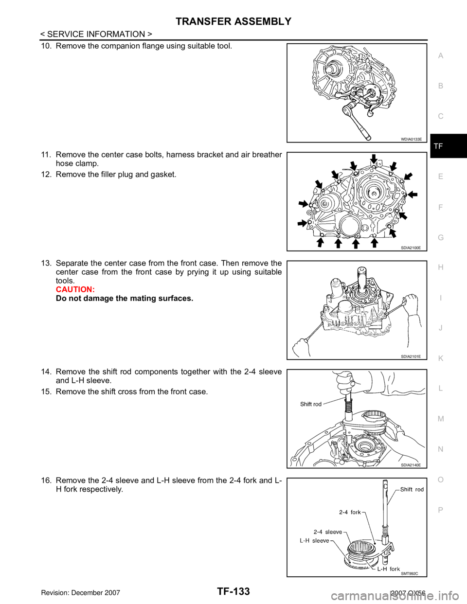
10. Remove the companion flange using suitable tool.
11. Remove the center case bolts, harness bracket and air breather
hose clamp.
12. Remove the filler plug and gasket.
13. Separate the center case from the front case. Then remove the
center case from the front case by prying it up using suitable
tools.
CAUTION:
Do not damage the mating surfaces.
14. Remove the shift rod components together with the 2-4 sleeve
and L-H sleeve.
15. Remove the shift cross from the front case.
16. Remove the 2-4 sleeve and L-H sleeve from the 2-4 fork and L-
H fork respectively.
WDIA0133E
SDIA2100E
SDIA2101E
SDIA2140E
SMT992C