wheel alignment INFINITI QX56 2007 Factory Service Manual
[x] Cancel search | Manufacturer: INFINITI, Model Year: 2007, Model line: QX56, Model: INFINITI QX56 2007Pages: 3061, PDF Size: 64.56 MB
Page 5 of 3061

2007
QUICK REFERENCE CHART: QX56
Drive Belt Deflection and Tension
Spark Plug (Platinum Tipped)
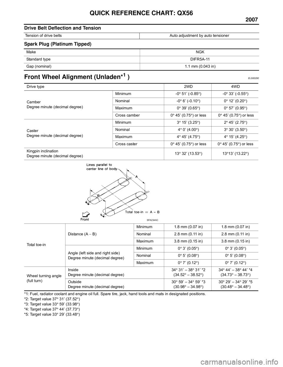
Front Wheel Alignment (Unladen*1 )ELS00290
*1: Fuel, radiator coolant and engine oil full. Spare tire, jack, hand tools and mats in designated positions.
*2: Target value 37° 31 ′ (37.52 °)
*3: Target value 33 ° 59 ′ (33.98 °)
*4: Target value 37 ° 44 ′ (37.73 °)
*5: Target value 33 ° 29 ′ (33.48 °)
Tension of drive belts Auto adjustment by auto tensioner
Make NGK
Standard type DIFR5A-11
Gap (nominal) 1.1 mm (0.043 in)
Drive type2WD 4WD
Camber
Degree minute (decimal degree) Minimum -0
° 51 ′ (-0.85 °)-0 ° 33 ′ (-0.55 °)
Nominal -0 ° 6 ′ (-0.10 °)0 ° 12 ′ (0.20 °)
Maximum 0 ° 39 ′ (0.65 °)0 ° 57 ′ (0.95 °)
Cross camber 0 ° 45 ′ (0.75 °) or less 0 ° 45 ′ (0.75 °) or less
Caster
Degree minute (decimal degree) Minimum 3
° 15 ′ (3.25 °)2 ° 45 ′ (2.75 °)
Nominal 4 ° 0 ′ (4.00 °)3 ° 30 ′ (3.50 °)
Maximum 4 ° 45 ′ (4.75 °)4 ° 15 ′ (4.25 °)
Cross caster 0 ° 45 ′ (0.75 °) or less 0 ° 45 ′ (0.75 °) or less
Kingpin inclination
Degree minute (decimal degree) 13
° 32 ′ (13.53 °)13 °13 ′ (13.22 °)
Total toe-in Distance (A
− B) Minimum 1.8 mm (0.07 in) 1.8 mm (0.07 in)
Nominal 2.8 mm (0.11 in) 2.8 mm (0.11 in)
Maximum 3.8 mm (0.15 in) 3.8 mm (0.15 in)
Angle (left side and right side)
Degree minute (decimal degree) Minimum 0
° 3 ′ (0.05 °)0 ° 3 ′ (0.05 °)
Nominal 0 ° 5 ′ (0.08 °)0 ° 5 ′ (0.08 °)
Maximum 0 ° 7 ′ (0.12 °)0 ° 7 ′ (0.12 °)
Wheel turning angle
(full turn) Inside
Degree minute (decimal degree)
34
° 31 ′ – 38 ° 31 ′ *2
(34.52 ° – 38.52 °) 34
° 44 ′ – 38 ° 44 ′ *4
(34.73 ° – 38.73 °)
Outside
Degree minute (decimal degree) 30
° 59 ′ – 34 ° 59 ′ *3
(30.98 ° – 34.98 °) 30
° 29 ′ – 34 ° 29 ′ *5
(30.48 ° – 34.48 °)
SFA234AC
Page 6 of 3061

QUICK REFERENCE CHART: QX56
2007
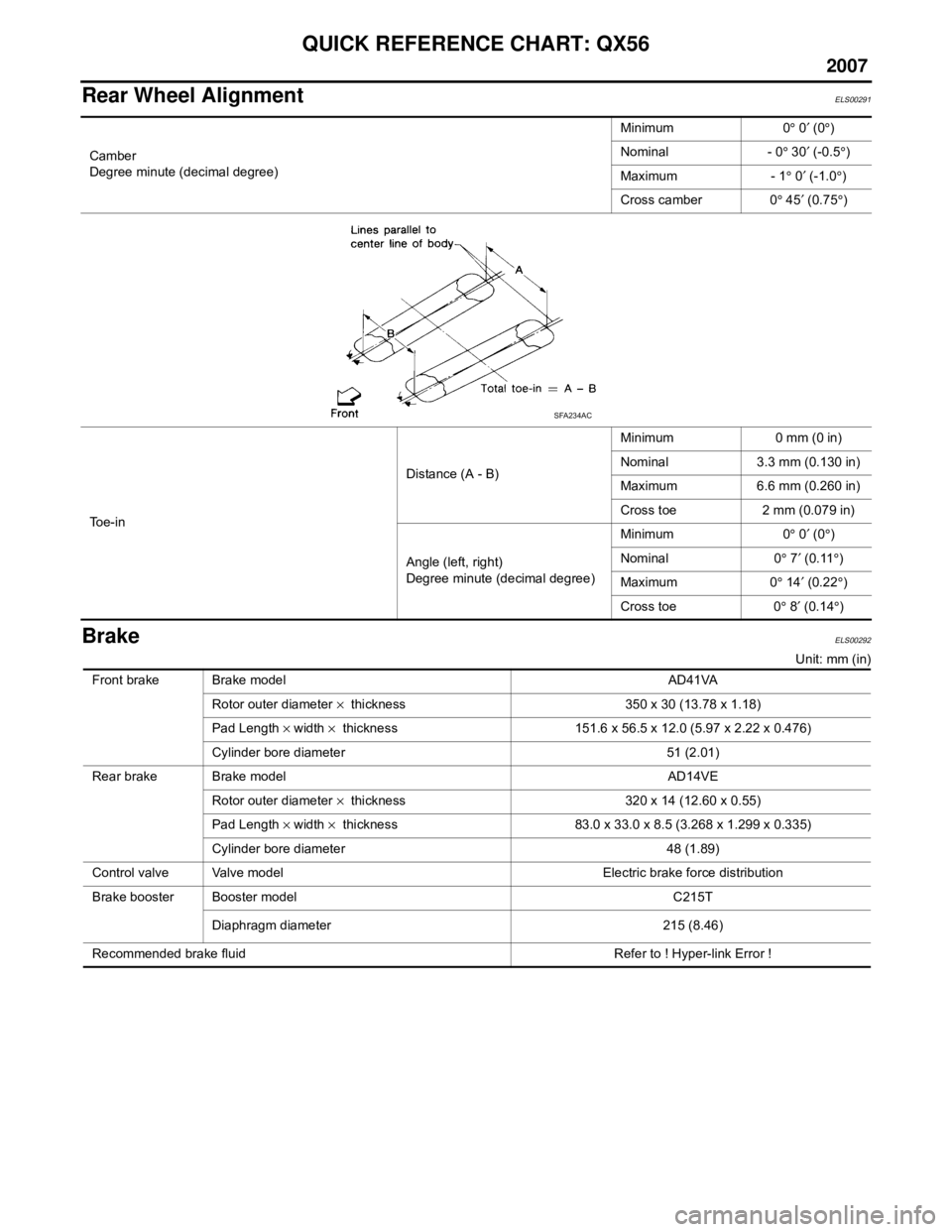
Rear Wheel AlignmentELS00291
BrakeELS00292
Unit: mm (in)
Camber
Degree minute (decimal degree)
Minimum 0
° 0 ′ (0 °)
Nominal - 0 ° 30 ′ (-0.5 °)
Maximum - 1 ° 0 ′ (-1.0 °)
Cross camber 0 ° 45 ′ (0.75 °)
To e - i n Distance (A - B)
Minimum 0 mm (0 in)
Nominal 3.3 mm (0.130 in)
Maximum 6.6 mm (0.260 in)
Cross toe 2 mm (0.079 in)
Angle (left, right)
Degree minute (decimal degree) Minimum 0
° 0 ′ (0 °)
Nominal 0 ° 7 ′ (0.11 °)
Maximum 0 ° 14 ′ (0.22 °)
Cross toe 0 ° 8 ′ (0.14 °)
SFA234AC
Front brake Brake model AD41VA
Rotor outer diameter × thickness 350 x 30 (13.78 x 1.18)
Pad Length × width × thickness 151.6 x 56.5 x 12.0 (5.97 x 2.22 x 0.476)
Cylinder bore diameter 51 (2.01)
Rear brake Brake model AD14VE Rotor outer diameter × thickness 320 x 14 (12.60 x 0.55)
Pad Length × width × thickness 83.0 x 33.0 x 8.5 (3.268 x 1.299 x 0.335)
Cylinder bore diameter 48 (1.89)
Control valve Valve model Electric brake force distribution
Brake booster Booster model C215T
Diaphragm diameter 215 (8.46)
Recommended brake fluid Refer to ! Hyper-link Error !
Page 982 of 3061
![INFINITI QX56 2007 Factory Service Manual BRC-54
< SERVICE INFORMATION >[VDC/TCS/ABS]
ON-VEHICLE SERVICE
ON-VEHICLE SERVICE
Adjustment of Steering Angle Sensor Neutral PositionINFOID:0000000003532809
After removing/installing or replacing ABS INFINITI QX56 2007 Factory Service Manual BRC-54
< SERVICE INFORMATION >[VDC/TCS/ABS]
ON-VEHICLE SERVICE
ON-VEHICLE SERVICE
Adjustment of Steering Angle Sensor Neutral PositionINFOID:0000000003532809
After removing/installing or replacing ABS](/img/42/57029/w960_57029-981.png)
BRC-54
< SERVICE INFORMATION >[VDC/TCS/ABS]
ON-VEHICLE SERVICE
ON-VEHICLE SERVICE
Adjustment of Steering Angle Sensor Neutral PositionINFOID:0000000003532809
After removing/installing or replacing ABS actuator and electric unit (control unit), steering angle sensor, steer-
ing and suspension components which affect wheel alignment or after adjusting wheel alignment, be sure to
adjust neutral position of steering angle sensor before running vehicle.
NOTE:
Adjustment of steering angle sensor neutral position requires CONSULT-II.
1. Stop vehicle with front wheels in straight-ahead position.
2. Connect CONSULT-II and CONSULT-II CONVERTER to data
link connector on vehicle, and turn ignition switch ON (do not
start engine).
3. Touch “START (NISSAN BASED VHCL)”, “ABS”, “WORK SUP-
PORT” and “ST ANGLE SENSOR ADJUSTMENT” on CON-
SULT-II screen in this order.
4. Touch “START”.
CAUTION:
Do not touch steering wheel while adjusting steering angle
sensor.
5. After approximately 10 seconds, touch “END”. (After approxi-
mately 60 seconds, it ends automatically.)
6. Turn ignition switch OFF, then turn it ON again.
7. Run vehicle with front wheels in straight-ahead position, then
stop.
8. Select “DATA MONITOR”, “SELECTION FROM MENU”, and
“STR ANGLE SIG” on CONSULT-II screen. Then check that
“STR ANGLE SIG” is within 0±3.5 deg. If value is more than specification, repeat steps 1 to 5.
9. Erase memory of ABS actuator and electric unit (control unit) and ECM.
10. Turn ignition switch to OFF.
Calibration of Decel G SensorINFOID:0000000003532810
After removing/installing or replacing ABS actuator and electric unit (control unit), yaw rate/side/decel G sen-
sor, steering and suspension components which affect wheel alignment or after adjusting wheel alignment, be
sure to calibrate the decel G sensor before running vehicle.
NOTE:
Calibration of decel G sensor requires CONSULT-II.
1. Stop vehicle with front wheels in straight-ahead position.
CAUTION:
• The work should be done on a level area with an unloaded vehicle.
• Keep all the tires inflated to the correct pressures. Adjust the tire pressure to the specified pres-
sure value.
2. Connect CONSULT-II with CONSULT-II CONVERTER to data link connector on vehicle, and turn ignition
switch ON (do not start engine).
CAUTION:
If CONSULT-II is used with no connection of CONSULT-II CONVERTER, malfunctions might be
detected in self-diagnosis depending on control unit which carries out CAN communication.
3. Touch “START (NISSAN BASED VHCL)”, "ABS", "WORK SUPPORT" and "DECEL G SEN CALIBRA-
TION" on CONSULT-II screen in this order. Refer to BRC-26, "
CONSULT-II Function (ABS)".
BBIA0369E
WFIA0239E
Page 1892 of 3061

FAX-6
< SERVICE INFORMATION >
WHEEL HUB
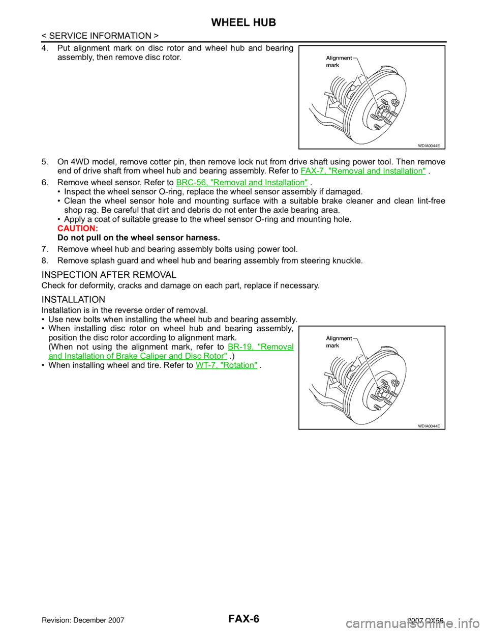
4. Put alignment mark on disc rotor and wheel hub and bearing
assembly, then remove disc rotor.
5. On 4WD model, remove cotter pin, then remove lock nut from drive shaft using power tool. Then remove
end of drive shaft from wheel hub and bearing assembly. Refer to FA X - 7 , "
Removal and Installation" .
6. Remove wheel sensor. Refer to BRC-56, "
Removal and Installation" .
• Inspect the wheel sensor O-ring, replace the wheel sensor assembly if damaged.
• Clean the wheel sensor hole and mounting surface with a suitable brake cleaner and clean lint-free
shop rag. Be careful that dirt and debris do not enter the axle bearing area.
• Apply a coat of suitable grease to the wheel sensor O-ring and mounting hole.
CAUTION:
Do not pull on the wheel sensor harness.
7. Remove wheel hub and bearing assembly bolts using power tool.
8. Remove splash guard and wheel hub and bearing assembly from steering knuckle.
INSPECTION AFTER REMOVAL
Check for deformity, cracks and damage on each part, replace if necessary.
INSTALLATION
Installation is in the reverse order of removal.
• Use new bolts when installing the wheel hub and bearing assembly.
• When installing disc rotor on wheel hub and bearing assembly,
position the disc rotor according to alignment mark.
(When not using the alignment mark, refer to BR-19, "
Removal
and Installation of Brake Caliper and Disc Rotor" .)
• When installing wheel and tire. Refer to WT-7, "
Rotation" .
WDIA0044E
WDIA0044E
Page 1947 of 3061

FSU-1
SUSPENSION
C
D
F
G
H
I
J
K
L
M
SECTION FSU
A
B
FSU
N
O
PCONTENTS
FRONT SUSPENSION
SERVICE INFORMATION ............................2
PRECAUTIONS ...................................................2
Precaution .................................................................2
PREPARATION ...................................................3
Special Service Tool .................................................3
Commercial Service Tool ..........................................3
NOISE, VIBRATION AND HARSHNESS
(NVH) TROUBLESHOOTING .............................
4
NVH Troubleshooting Chart ......................................4
FRONT SUSPENSION ASSEMBLY ...................5
Component ................................................................5
ON-VEHICLE SERVICE ......................................6
Front Suspension Parts .............................................6
Front Wheel Alignment ..............................................6
COIL SPRING AND SHOCK ABSORBER ........10
Removal and Installation .........................................10
Disassembly and Assembly ....................................10
STABILIZER BAR ..............................................12
Removal and Installation .........................................12
UPPER LINK .....................................................13
Removal and Installation .........................................13
LOWER LINK ....................................................14
Removal and Installation .........................................14
UPPER BALL JOINT AND LOWER BALL
JOINT ................................................................
15
Removal and Installation .........................................15
Inspection ................................................................15
KNUCKLE .........................................................17
On-Vehicle Inspection and Service .........................17
Removal and Installation .........................................17
SERVICE DATA AND SPECIFICATIONS
(SDS) .................................................................
19
General Specification ..............................................19
Spring Free Height ..................................................19
Wheel Alignment (Unladen*1) *6 .............................19
Ball Joint ..................................................................20
Wheelarch Height (Unladen*1) ................................20
Page 1948 of 3061

FSU-2
< SERVICE INFORMATION >
PRECAUTIONS
SERVICE INFORMATION
PRECAUTIONS
PrecautionINFOID:0000000003532631
• When installing the rubber bushings, the final tightening must be done under unladen condition and with the
tires on level ground. Oil will shorten the life of the rubber bushings, so wipe off any spilled oil immediately.
• Unladen condition means the fuel tank, engine coolant and lubricants are at the full specification. The spare
tire, jack, hand tools, and mats are in their designated positions.
• After installing suspension components, check the wheel alignment.
• Lock nuts are not reusable. Always use new lock nuts for installation. New lock nuts are pre-oiled, do not
apply any additional lubrication.
Page 1949 of 3061

PREPARATION
FSU-3
< SERVICE INFORMATION >
C
D
F
G
H
I
J
K
L
MA
B
FSU
N
O
P
PREPARATION
Special Service ToolINFOID:0000000003532632
The actual shapes of Kent-Moore tools may differ from those of special service tools illustrated here.
Commercial Service ToolINFOID:0000000003532633
Tool number
(Kent-Moore No.)
Tool nameDescription
ST29020001
(J-24319-01)
Pitman arm pullerRemoving upper link ball joint from knuckle
spindle
a: 34 mm (1.34 in)
b: 6.5 mm (0.256 in)
c: 61.5 mm (2.421 in)
HT72520000
(J-25730-A)
Ball joint removerRemoving tie-rod outer end
NT694
NT146
Tool nameDescription
Attachment wheel alignment Measure wheel alignment
a: Screw M24 x 1.5 pitch
b: 35 mm (1.38 in) dia.
c: 65 mm (2.56 in) dia.
d: 56 mm (2.20 in)
e: 12 mm (0.47 in)
Spring compressor Removing and installing coil spring
Power toolLoosening bolts and nuts
NT148
NT717
PBIC0190E
Page 1950 of 3061

FSU-4
< SERVICE INFORMATION >
NOISE, VIBRATION AND HARSHNESS (NVH) TROUBLESHOOTING
NOISE, VIBRATION AND HARSHNESS (NVH) TROUBLESHOOTING
NVH Troubleshooting ChartINFOID:0000000003532634
Use the chart below to help you find the cause of the symptom. Repair or replace parts as necessary.
x: ApplicableReference page
FSU-5FSU-10FSU-5FSU-5FSU-20FSU-6FSU-6FSU-6
PR-3, "
NVH Troubleshooting Chart
"
FFD-6, "
NVH Troubleshooting Chart
"
FAX-4, "
NVH Troubleshooting Chart
"
FAX-4, "
NVH Troubleshooting Chart
"
WT-4, "
NVH Troubleshooting Chart
"
WT-4, "
NVH Troubleshooting Chart
"
BR-4, "
NVH Troubleshooting Chart
"
PS-5, "
NVH Troubleshooting Chart
"
Possible Cause and
SUSPECTED PARTS
Improper installation, looseness
Shock absorber deformation,
damage or deflection
Bushing or mounting deterioration
Parts interference
Spring fatigue
Suspension looseness
Incorrect wheel alignment
Stabilizer bar fatigue
PROPELLER SHAFT
FRONT FINAL DRIVE
DRIVE SHAFT
WHEEL HUB
TIRES
ROAD WHEEL
BRAKES
STEERING
SymptomNoise× × ×××× × × ×× × × ××
Shake× × ×× × × ×× × × ××
Vibration× × ××× × ×× × ×
Shimmy× × ×× × × × × ××
Shudder××× ×××××
Poor quality ride or handling××××× ×× ×××
Page 1952 of 3061

FSU-6
< SERVICE INFORMATION >
ON-VEHICLE SERVICE
ON-VEHICLE SERVICE
Front Suspension PartsINFOID:0000000003532636
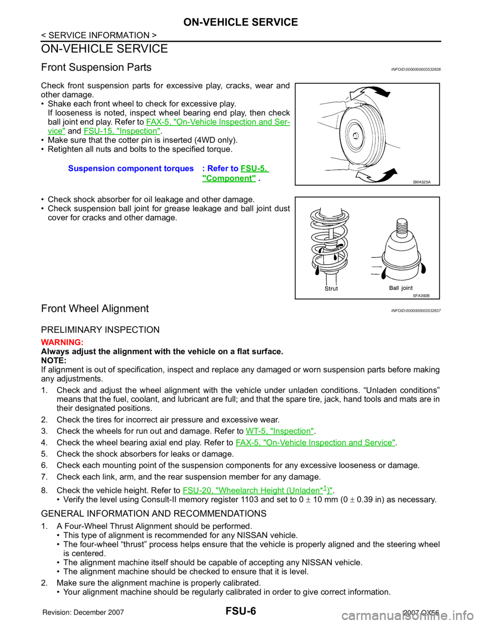
Check front suspension parts for excessive play, cracks, wear and
other damage.
• Shake each front wheel to check for excessive play.
If looseness is noted, inspect wheel bearing end play, then check
ball joint end play. Refer to FA X - 5 , "
On-Vehicle Inspection and Ser-
vice" and FSU-15, "Inspection".
• Make sure that the cotter pin is inserted (4WD only).
• Retighten all nuts and bolts to the specified torque.
• Check shock absorber for oil leakage and other damage.
• Check suspension ball joint for grease leakage and ball joint dust
cover for cracks and other damage.
Front Wheel AlignmentINFOID:0000000003532637
PRELIMINARY INSPECTION
WARNING:
Always adjust the alignment with the vehicle on a flat surface.
NOTE:
If alignment is out of specification, inspect and replace any damaged or worn suspension parts before making
any adjustments.
1. Check and adjust the wheel alignment with the vehicle under unladen conditions. “Unladen conditions”
means that the fuel, coolant, and lubricant are full; and that the spare tire, jack, hand tools and mats are in
their designated positions.
2. Check the tires for incorrect air pressure and excessive wear.
3. Check the wheels for run out and damage. Refer to WT-5, "
Inspection".
4. Check the wheel bearing axial end play. Refer to FA X - 5 , "
On-Vehicle Inspection and Service".
5. Check the shock absorbers for leaks or damage.
6. Check each mounting point of the suspension components for any excessive looseness or damage.
7. Check each link, arm, and the rear suspension member for any damage.
8. Check the vehicle height. Refer to FSU-20, "
Wheelarch Height (Unladen*1)".
• Verify the level using Consult-II memory register 1103 and set to 0 ± 10 mm (0 ± 0.39 in) as necessary.
GENERAL INFORMATION AND RECOMMENDATIONS
1. A Four-Wheel Thrust Alignment should be performed.
• This type of alignment is recommended for any NISSAN vehicle.
• The four-wheel “thrust” process helps ensure that the vehicle is properly aligned and the steering wheel
is centered.
• The alignment machine itself should be capable of accepting any NISSAN vehicle.
• The alignment machine should be checked to ensure that it is level.
2. Make sure the alignment machine is properly calibrated.
• Your alignment machine should be regularly calibrated in order to give correct information.Suspension component torques : Refer to FSU-5,
"Component" . SMA525A
SFA392B
Page 1953 of 3061

ON-VEHICLE SERVICE
FSU-7
< SERVICE INFORMATION >
C
D
F
G
H
I
J
K
L
MA
B
FSU
N
O
P
• Check with the manufacturer of your specific alignment machine for their recommended Service/Cali-
bration Schedule.
THE ALIGNMENT PROCESS
IMPORTANT: Use only the alignment specifications listed in this Service Manual. Refer to FSU-19, "Wheel
Alignment (Unladen*1) *6".
1. When displaying the alignment settings, many alignment machines use “indicators”: (Green/red, plus or
minus, Go/No Go). Do NOT use these indicators.
• The alignment specifications programmed into your alignment machine that operate these indicators
may not be correct.
• This may result in an ERROR.
2. Some newer alignment machines are equipped with an optional “Rolling Compensation” method to “com-
pensate” the sensors (alignment targets or head units). Do NOT use this “Rolling Compensation”
method.
• Use the “Jacking Compensation” method. After installing the alignment targets or head units, raise the
vehicle and rotate the wheels 1/2 turn both ways.
• See Instructions in the alignment machine you are using for more information.
CAMBER AND CASTER
1. Measure camber and caster of both the right and left wheels
with a suitable alignment gauge and adjust as necessary to
specification.
NOTE:
Some vehicles may be equipped with straight (non-adjustable)
lower link bolts and washers. In order to adjust camber and
caster on these vehicles, first replace the lower link bolts and
washers with adjustable (cam) bolts and washers.
2. If outside of the specified value, adjust camber and caster using
the cam bolts (1) in the front lower link (2).
CAUTION:
After adjusting the camber then check the toe-in.
NOTE:
Camber changes about 3' (0.05°) minutes with each graduation
of one cam bolt. Refer to table below for examples of lower link
cam bolt effect on camber and caster.
3. Tighten the adjusting bolt nuts to specification. Refer to FSU-5, "
Component".
TOE-IN
WARNING:
• Always perform the following procedure on a flat surface.
• Make sure that no person is in front of the vehicle before pushing it.Camber and
Caster: Refer to FSU-19, "
Wheel Alignment
(Unladen*1) *6" .
SRA096A
WEIA0153E
Rear cam bolt 1 In 1 Out 1 In 1 Out 0 0 1 In 1 Out
Front cam bolt 1 Out 1 In 1 In 1 Out 1 In 1 Out 0 0
Camber
Degree minute
(Decimal degree)0 (0) 0 (0) 7' (0.12°) - 7' (-0.12°)3' (0.05°) - 3' (-0.05°)3' (0.05°) - 3' (-0.05°)
Caster
Degree minute
(Decimal degree)- 14' (-0.23°)14' (0.23°) 0 (0) 0 (0) 7' (0.12°) - 7' (-0.12°) - 7' (-0.12°)7' (0.12°)