brake INFINITI QX56 2007 Factory Service Manual
[x] Cancel search | Manufacturer: INFINITI, Model Year: 2007, Model line: QX56, Model: INFINITI QX56 2007Pages: 3061, PDF Size: 64.56 MB
Page 350 of 3061
AT-280
< SERVICE INFORMATION >
ASSEMBLY
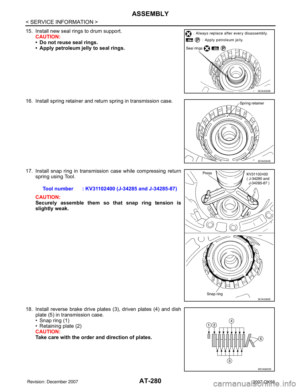
15. Install new seal rings to drum support.
CAUTION:
• Do not reuse seal rings.
• Apply petroleum jelly to seal rings.
16. Install spring retainer and return spring in transmission case.
17. Install snap ring in transmission case while compressing return
spring using Tool.
CAUTION:
Securely assemble them so that snap ring tension is
slightly weak.
18. Install reverse brake drive plates (3), driven plates (4) and dish
plate (5) in transmission case.
• Snap ring (1)
• Retaining plate (2)
CAUTION:
Take care with the order and direction of plates.
SCIA3333E
SCIA2324E
Tool number : KV31102400 (J-34285 and J-34285-87)
SCIA5582E
WCIA0625E
Page 351 of 3061
ASSEMBLY
AT-281
< SERVICE INFORMATION >
D
E
F
G
H
I
J
K
L
MA
B
AT
N
O
P
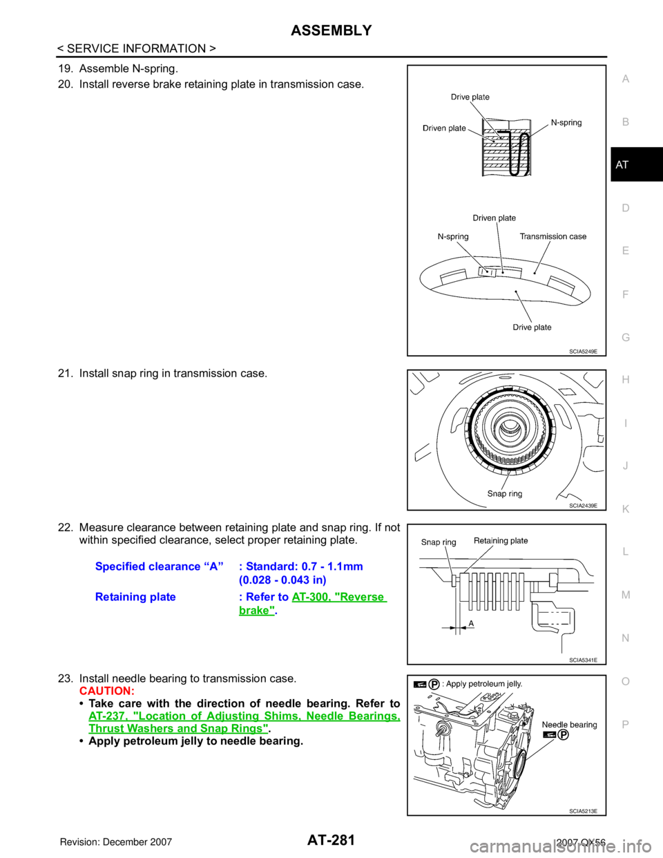
19. Assemble N-spring.
20. Install reverse brake retaining plate in transmission case.
21. Install snap ring in transmission case.
22. Measure clearance between retaining plate and snap ring. If not
within specified clearance, select proper retaining plate.
23. Install needle bearing to transmission case.
CAUTION:
• Take care with the direction of needle bearing. Refer to
AT-237, "
Location of Adjusting Shims, Needle Bearings,
Thrust Washers and Snap Rings".
• Apply petroleum jelly to needle bearing.
SCIA5249E
SCIA2439E
Specified clearance “A” : Standard: 0.7 - 1.1mm
(0.028 - 0.043 in)
Retaining plate : Refer to AT-300, "
Reverse
brake".
SCIA5341E
SCIA5213E
Page 356 of 3061
AT-286
< SERVICE INFORMATION >
ASSEMBLY
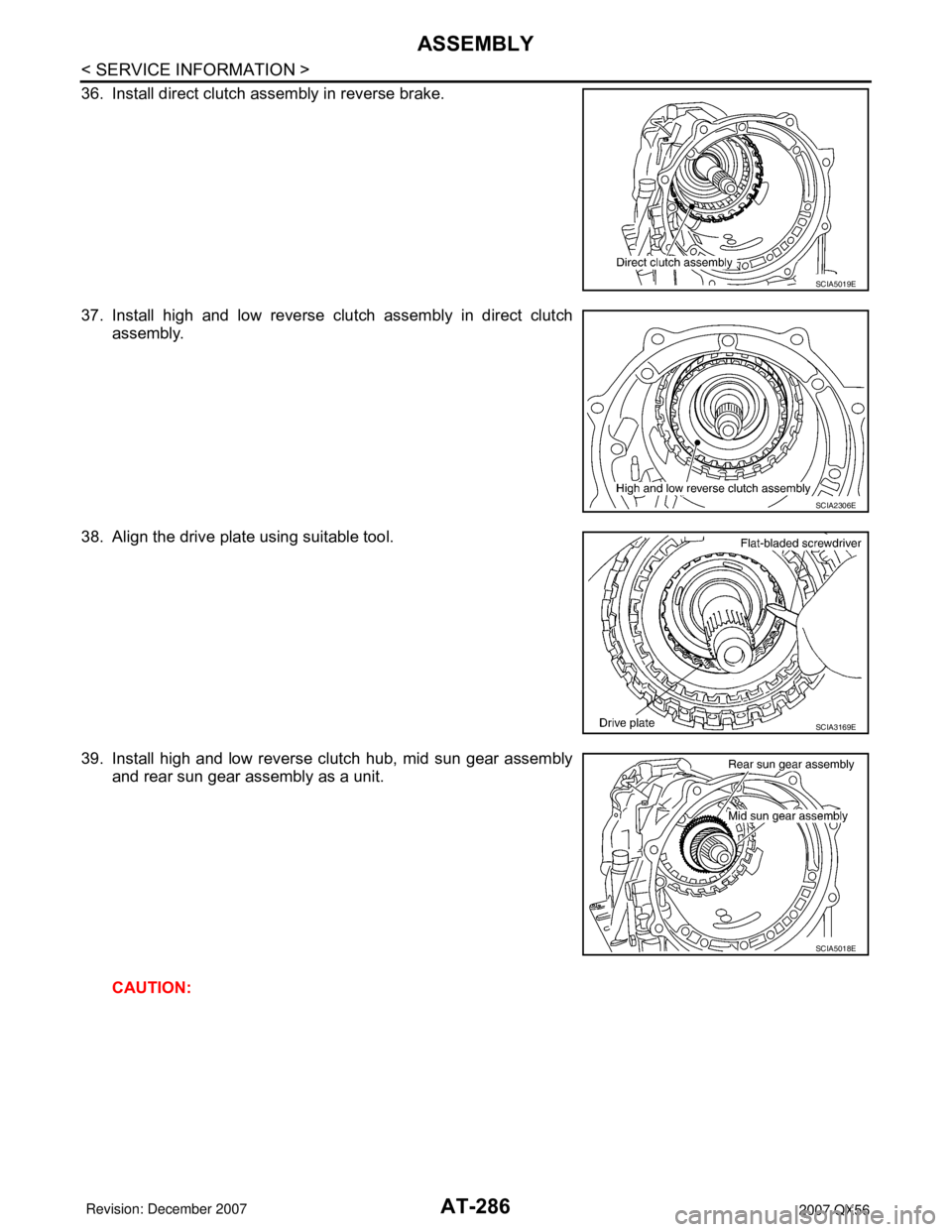
36. Install direct clutch assembly in reverse brake.
37. Install high and low reverse clutch assembly in direct clutch
assembly.
38. Align the drive plate using suitable tool.
39. Install high and low reverse clutch hub, mid sun gear assembly
and rear sun gear assembly as a unit.
CAUTION:
SCIA5019E
SCIA2306E
SCIA3169E
SCIA5018E
Page 359 of 3061
ASSEMBLY
AT-289
< SERVICE INFORMATION >
D
E
F
G
H
I
J
K
L
MA
B
AT
N
O
P
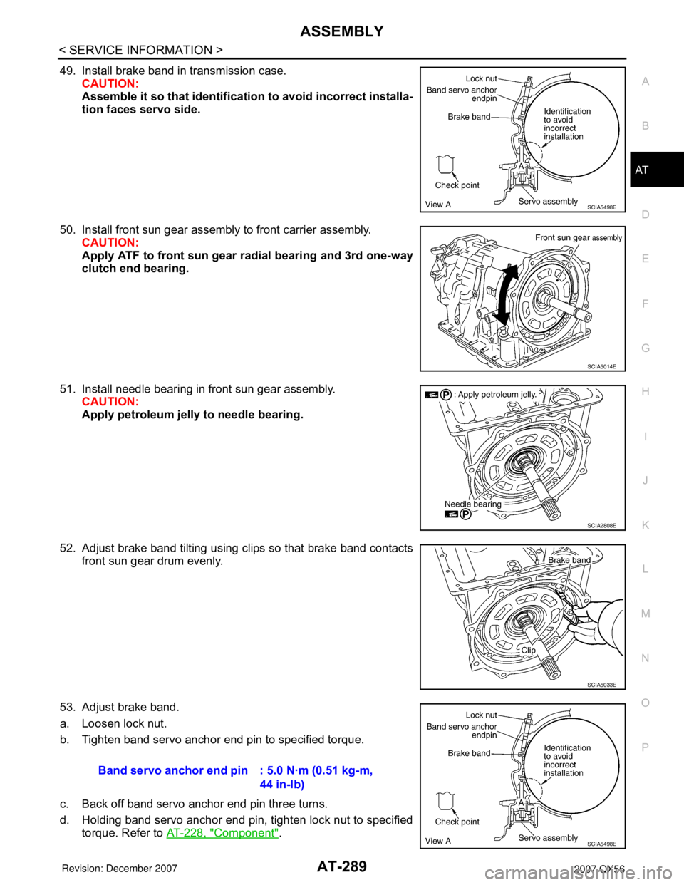
49. Install brake band in transmission case.
CAUTION:
Assemble it so that identification to avoid incorrect installa-
tion faces servo side.
50. Install front sun gear assembly to front carrier assembly.
CAUTION:
Apply ATF to front sun gear radial bearing and 3rd one-way
clutch end bearing.
51. Install needle bearing in front sun gear assembly.
CAUTION:
Apply petroleum jelly to needle bearing.
52. Adjust brake band tilting using clips so that brake band contacts
front sun gear drum evenly.
53. Adjust brake band.
a. Loosen lock nut.
b. Tighten band servo anchor end pin to specified torque.
c. Back off band servo anchor end pin three turns.
d. Holding band servo anchor end pin, tighten lock nut to specified
torque. Refer to AT-228, "
Component".
SCIA5498E
SCIA5014E
SCIA2808E
SCIA5033E
Band servo anchor end pin : 5.0 N·m (0.51 kg-m,
44 in-lb)
SCIA5498E
Page 363 of 3061
ASSEMBLY
AT-293
< SERVICE INFORMATION >
D
E
F
G
H
I
J
K
L
MA
B
AT
N
O
P
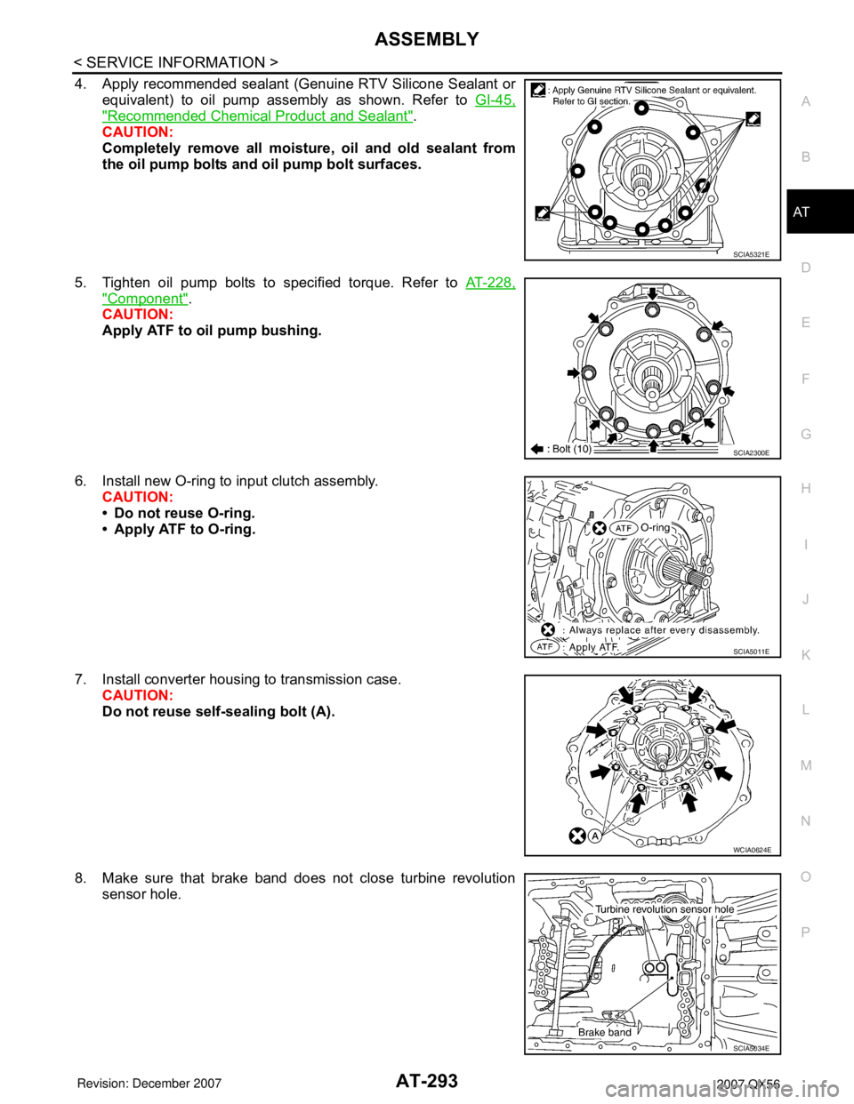
4. Apply recommended sealant (Genuine RTV Silicone Sealant or
equivalent) to oil pump assembly as shown. Refer to GI-45,
"Recommended Chemical Product and Sealant".
CAUTION:
Completely remove all moisture, oil and old sealant from
the oil pump bolts and oil pump bolt surfaces.
5. Tighten oil pump bolts to specified torque. Refer to AT-228,
"Component".
CAUTION:
Apply ATF to oil pump bushing.
6. Install new O-ring to input clutch assembly.
CAUTION:
• Do not reuse O-ring.
• Apply ATF to O-ring.
7. Install converter housing to transmission case.
CAUTION:
Do not reuse self-sealing bolt (A).
8. Make sure that brake band does not close turbine revolution
sensor hole.
SCIA5321E
SCIA2300E
SCIA5011E
WCIA0624E
SCIA5034E
Page 370 of 3061

AT-300
< SERVICE INFORMATION >
SERVICE DATA AND SPECIFICATIONS (SDS)
Reverse brake
INFOID:0000000003532504
*: Always check with the Parts Department for the latest parts information.
Total End PlayINFOID:0000000003532505
BEARING RACE FOR ADJUSTING TOTAL END PLAY
*: Always check with the Parts Department for the latest parts information.Thickness of retaining platesThickness mm (in) Part number*
4.2 (0.165)
4.4 (0.173)
4.6 (0.181)
4.8 (0.189)
5.0 (0.197)
5.2 (0.205) 31667 90X14
31667 90X15
31667 90X16
31667 90X17
31667 90X18
31667 90X19
Total end play mm (in) 0.25 - 0.55 (0.0098 - 0.0217)
Thickness mm (in) Part number*
0.8 (0.031)
1.0 (0.039)
1.2 (0.047)
1.4 (0.055)
1.6 (0.063)
1.8 (0.071)31435 95X00
31435 95X01
31435 95X02
31435 95X03
31435 95X04
31435 95X05
Page 853 of 3061

BL-142
< SERVICE INFORMATION >
BODY REPAIR
6. 2nd crossmember assembly
7. Front upper link mounting bracket RH/LH
8. Panhard rod bracket reinforcement
9. Bound bumper bracket RH/LH
10. Front brake hose bracket RH/LH
11. Panhard rod reinforcement
12. 4th crossmember gusset RH/LH
13. 2nd cab mounting bracket RH/LH
14. 3rd cab mounting bracket RH/LH
15. 4th cab mounting reinforcement RH/LH
16. 4th cab mounting bracket RH/LH
17. Rear suspension mounting bracket RH/LH
18. Rear brake hose bracket
19. Rear shock absorber bracket assembly RH/LH
20. Rear bound bumper bracket RH/LH
21. Rear bracket bumper reinforcement RH/LH
22. Cab mounting bracket assembly RH/LH
23. 9th crossmember assembly
24. Exhaust bracket assembly
25. Canister bracket, LH
26. 7th crossmember reinforcement
27. 7th crossmember assembly
28. 6th crossmember assembly
29. 4th crossmember gusset RH/LH
30. 4th crossmember assembly
31. 3rd crossmember assembly
32. Frame assembly
Corrosion ProtectionINFOID:0000000003533007
DESCRIPTION
To provide improved corrosion prevention, the following anti-corrosive measures have been implemented in
NISSAN production plants. When repairing or replacing body panels, it is necessary to use the same anti-cor-
rosive measures.
ANTI-CORROSIVE PRECOATED STEEL (GALVANNEALED STEEL)
To improve repairability and corrosion resistance, a new type of anti-
corrosive precoated steel sheet has been adopted replacing conven-
tional zinc-coated steel sheet.
Galvannealed steel is electroplated and heated to form Zinc-iron
alloy, which provides excellent and long term corrosion resistance
with cationic electrode position primer.
Nissan Genuine Service Parts are fabricated from galvannealed steel. Therefore, it is recommended that
GENUINE NISSAN PARTS or equivalent be used for panel replacement to maintain the anti-corrosive perfor-
mance built into the vehicle at the factory.
PHOSPHATE COATING TREATMENT AND CATIONIC ELECTRODEPOSITION PRIMER
PIIA0093E
Page 899 of 3061

BR-1
BRAKES
C
D
E
G
H
I
J
K
L
M
SECTION BR
A
B
BR
N
O
P
CONTENTS
BRAKE SYSTEM
SERVICE INFORMATION ............................2
PRECAUTIONS ...................................................2
Precaution for Supplemental Restraint System
(SRS) "AIR BAG" and "SEAT BELT PRE-TEN-
SIONER" ...................................................................
2
Precaution for Brake System ....................................2
PREPARATION ...................................................3
Special Service Tool .................................................3
Commercial Service Tool ..........................................3
NOISE, VIBRATION AND HARSHNESS
(NVH) TROUBLESHOOTING .............................
4
NVH Troubleshooting Chart ......................................4
BRAKE PEDAL ...................................................5
Inspection and Adjustment ........................................5
Removal and Installation ...........................................6
BRAKE FLUID .....................................................8
On Board Inspection .................................................8
Drain and Refill ..........................................................8
Bleeding Brake System .............................................8
BRAKE PIPING AND HOSE ..............................10
Hydraulic Circuit ......................................................10
Removal and Installation of Front Brake Hose ........10
Removal and Installation of Rear Brake Hose ........11
Inspection After Installation .....................................12
BRAKE MASTER CYLINDER ............................13
On Board Inspection ...............................................13
Removal and Installation .........................................13
Disassembly and Assembly ....................................14
BRAKE BOOSTER ...........................................15
On-Vehicle Service ..................................................15
Removal and Installation .........................................15
VACUUM LINES ...............................................17
Removal and Installation .........................................17
Inspection ................................................................17
FRONT DISC BRAKE .......................................18
On-vehicle Inspection ..............................................18
Component ..............................................................18
Removal and Installation of Brake Pad ...................19
Removal and Installation of Brake Caliper and
Disc Rotor ................................................................
19
Disassembly and Assembly of Brake Caliper ..........20
REAR DISC BRAKE .........................................24
On-vehicle Inspection ..............................................24
Exploded View .........................................................24
Removal and Installation of Brake Pad ...................25
Removal and Installation of Brake Caliper and
Disc Rotor ................................................................
25
Brake Caliper ...........................................................26
SERVICE DATA AND SPECIFICATIONS
(SDS) .................................................................
29
General Specification ..............................................29
Brake Pedal .............................................................29
Brake Booster ..........................................................30
Check Valve ............................................................30
Front Disc Brake ......................................................30
Rear Disc Brake ......................................................30
Page 900 of 3061
BR-2
< SERVICE INFORMATION >
PRECAUTIONS
SERVICE INFORMATION
PRECAUTIONS
Precaution for Supplemental Restraint System (SRS) "AIR BAG" and "SEAT BELT
PRE-TENSIONER"
INFOID:0000000003532717
The Supplemental Restraint System such as “AIR BAG” and “SEAT BELT PRE-TENSIONER”, used along
with a front seat belt, helps to reduce the risk or severity of injury to the driver and front passenger for certain
types of collision. This system includes seat belt switch inputs and dual stage front air bag modules. The SRS
system uses the seat belt switches to determine the front air bag deployment, and may only deploy one front
air bag, depending on the severity of a collision and whether the front occupants are belted or unbelted.
Information necessary to service the system safely is included in the SRS and SB section of this Service Man-
ual.
WARNING:
• To avoid rendering the SRS inoperative, which could increase the risk of personal injury or death in
the event of a collision which would result in air bag inflation, all maintenance must be performed by
an authorized NISSAN/INFINITI dealer.
• Improper maintenance, including incorrect removal and installation of the SRS, can lead to personal
injury caused by unintentional activation of the system. For removal of Spiral Cable and Air Bag
Module, see the SRS section.
• Do not use electrical test equipment on any circuit related to the SRS unless instructed to in this
Service Manual. SRS wiring harnesses can be identified by yellow and/or orange harnesses or har-
ness connectors.
Precaution for Brake SystemINFOID:0000000003532718
• Always use recommended brake fluid. Refer to MA-10 .
• Do not reuse drained brake fluid.
• Be careful not to splash brake fluid on painted areas.
• To clean or wash all parts of master cylinder, disc brake caliper and wheel cylinder, use clean brake fluid.
• Do not use mineral oils such as gasoline or kerosene. They will ruin rubber parts of the hydraulic system.
• Use flare nut wrench when removing and installing brake tube.
• Always check tightening torque when installing brake lines.
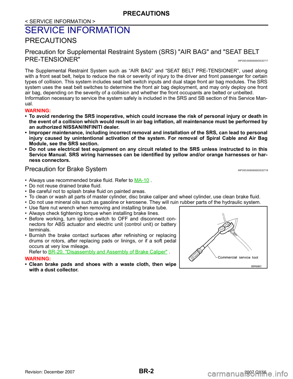
• Before working, turn ignition switch to OFF and disconnect con-
nectors for ABS actuator and electric unit (control unit) or battery
terminals.
• Burnish the brake contact surfaces after refinishing or replacing
drums or rotors, after replacing pads or linings, or if a soft pedal
occurs at very low mileage.
Refer to BR-20, "
Disassembly and Assembly of Brake Caliper" .
WARNING:
• Clean brake pads and shoes with a waste cloth, then wipe
with a dust collector.
SBR686C
Page 901 of 3061

PREPARATION
BR-3
< SERVICE INFORMATION >
C
D
E
G
H
I
J
K
L
MA
B
BR
N
O
P
PREPARATION
Special Service ToolINFOID:0000000003532719
The actual shapes of Kent-Moore tools may differ from those of special service tools illustrated here.
Commercial Service ToolINFOID:0000000003532720
Tool number
(Kent-Moore No.)
Tool nameDescription
—
(J-46532)
Brake and clutch pedal height measure-
ment toolMeasuring brake pedal height
LFIA0227E
Tool nameDescription
1. Flare nut crowfoot
2. Torque wrenchRemoving and installing each brake pip-
ing.
a: 10 mm (0.39 in) / 12 mm (0.47 in)
Power toolRemoving nuts, bolts and screws.
S-NT360
PBIC0190E
PBIC0191E