door lock INFINITI QX56 2007 Factory Service Manual
[x] Cancel search | Manufacturer: INFINITI, Model Year: 2007, Model line: QX56, Model: INFINITI QX56 2007Pages: 3061, PDF Size: 64.56 MB
Page 417 of 3061
TROUBLE DIAGNOSISATC-47
< SERVICE INFORMATION >
C
DE
F
G H
I
K L
M A
B
AT C
N
O P
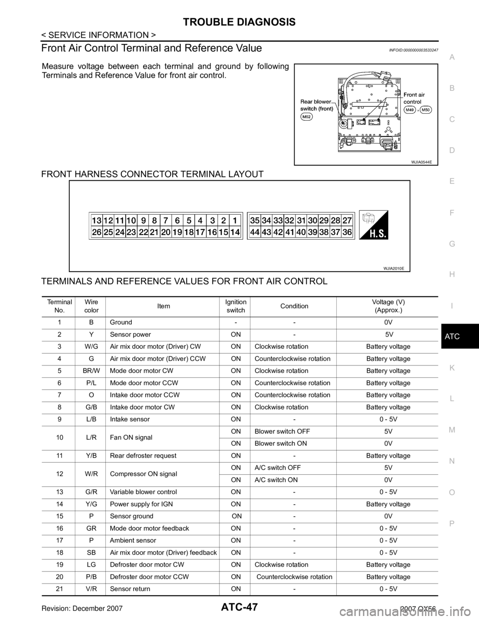
Front Air Control Termina l and Reference ValueINFOID:0000000003533247
Measure voltage between each terminal and ground by following
Terminals and Reference Value for front air control.
FRONT HARNESS CONNECTOR TERMINAL LAYOUT
TERMINALS AND REFERENCE VALUES FOR FRONT AIR CONTROL
WJIA0544E
WJIA2010E
Te r m i n a l
No. Wire
color ItemIgnition
switch Condition Voltage (V)
(Approx.)
1 B Ground - - 0V
2 Y Sensor power ON - 5V
3 W/G Air mix door motor (Driver) CW ON Clockwise rotation Battery voltage
4 G Air mix door motor (Driver) CCW ON Coun terclockwise rotation Battery voltage
5 BR/W Mode door motor CW ON Clockwise rotation Battery voltage
6 P/L Mode door motor CCW ON Counterclockw ise rotation Battery voltage
7 O Intake door motor CCW ON Counterclockwise rotation Battery voltage
8 G/B Intake door motor CW ON Clockwise rotation Battery voltage
9 L/B Intake sensor ON - 0 - 5V
10 L/R Fan ON signal ON Blower switch OFF 5V
ON Blower switch ON 0V
11 Y/B Rear defroster requ est ON - Battery voltage
12 W/R Compressor ON signal ON A/C switch OFF 5V
ON A/C switch ON 0V
13 G/R Variable blower control ON - 0 - 5V
14 Y/G Power supply for IGN ON - Battery voltage
15 P Sensor ground ON - 0V
16 GR Mode door motor feedback ON - 0 - 5V
17 P Ambient sensor ON - 0 - 5V
18 SB Air mix door motor (D river) feedback ON - 0 - 5V
19 LG Defroster door motor CW ON Clockwise rotation Battery voltage
20 P/B Defroster door motor CCW ON Counterclockwise rotation Battery voltage
21 V/R Sensor return ON - 0 - 5V
Page 418 of 3061
ATC-48
< SERVICE INFORMATION >
TROUBLE DIAGNOSIS
A/C System Self-Diagnosis Function
INFOID:0000000003533248
DESCRIPTION
22 Y/R Power supply for BAT - - Battery voltage
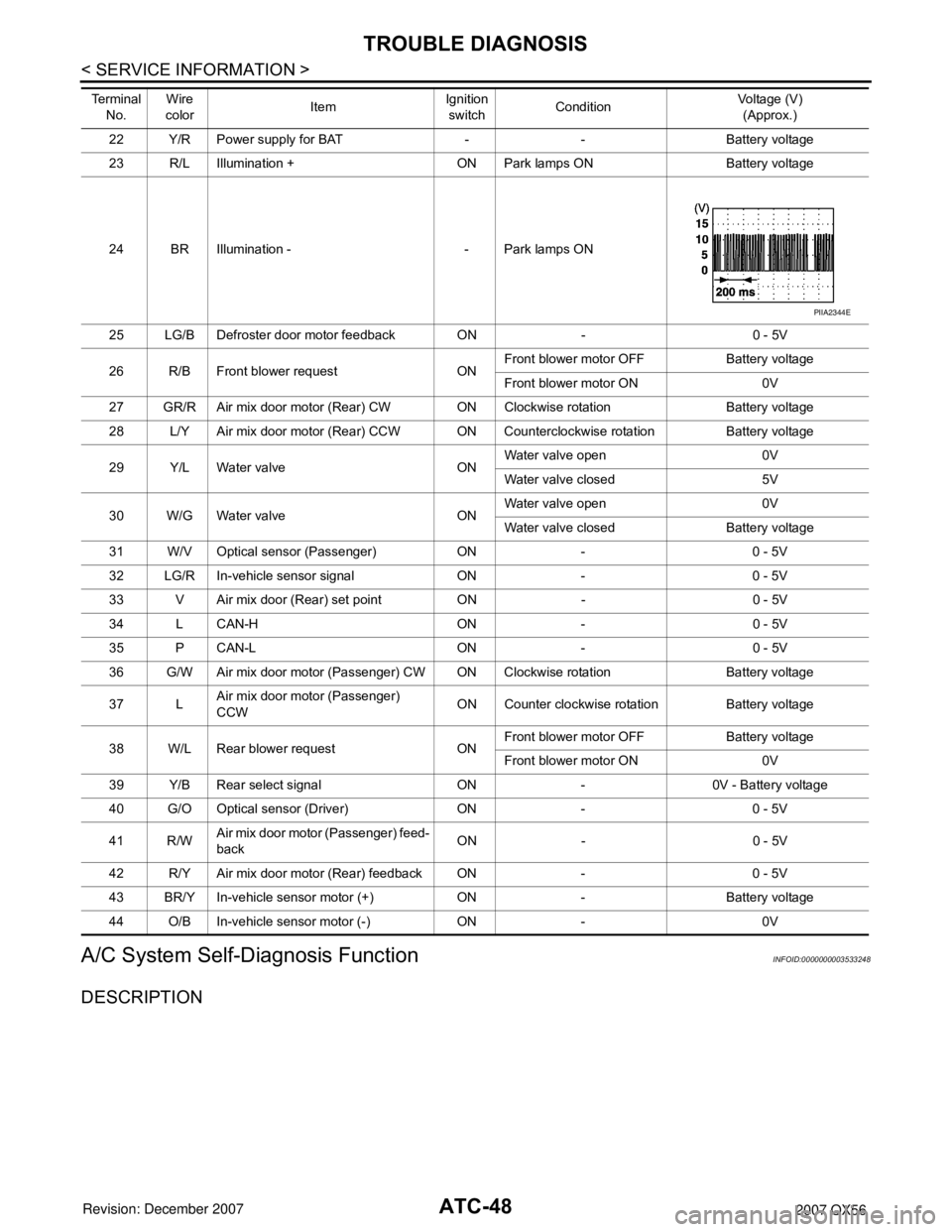
23 R/L Illumination + ON Park lamps ON Battery voltage
24 BR Illumination - - Park lamps ON
25 LG/B Defroster door motor feedback ON - 0 - 5V
26 R/B Front blower request ON Front blower motor OFF Battery voltage
Front blower motor ON 0V
27 GR/R Air mix door motor (Rear) CW ON Clockwise rotation Battery voltage
28 L/Y Air mix door motor (Rear) CCW ON Coun terclockwise rotation Battery voltage
29 Y/L Water valve ON Water valve open 0V
Water valve closed 5V
30 W/G Water valve ON Water valve open 0V
Water valve closed Battery voltage
31 W/V Optical sensor (Passenger) ON - 0 - 5V
32 LG/R In-vehicle sensor signal ON - 0 - 5V
33 V Air mix door (Rear) set point ON - 0 - 5V
34 L CAN-H ON - 0 - 5V
35 P CAN-L ON - 0 - 5V
36 G/W Air mix door motor (Passenger) CW ON Clockwise rotation Battery voltage
37 L Air mix door motor (Passenger)
CCW ON Counter clockwise rotation Battery voltage
38 W/L Rear blower request ON Front blower motor OFF Battery voltage
Front blower motor ON 0V
39 Y/B Rear select signal ON - 0V - Battery voltage
40 G/O Optical sensor (Driver) ON - 0 - 5V
41 R/W Air mix door motor (Passenger) feed-
back ON - 0 - 5V
42 R/Y Air mix door motor (Rear) feedback ON - 0 - 5V
43 BR/Y In-vehicle sensor motor (+) ON - Battery voltage
44 O/B In-vehicle sensor motor (-) ON - 0V
Te r m i n a l
No. Wire
color ItemIgnition
switch Condition Voltage (V)
(Approx.)
PIIA2344E
Page 420 of 3061
ATC-50
< SERVICE INFORMATION >
TROUBLE DIAGNOSIS
Operational Check (Front)
INFOID:0000000003533249
The purpose of the operational check is to confirm that the system operates properly.
CHECKING MEMORY FUNCTION
1. Set the temperature to 90 °F or 32 °C.
2. Turn front blower control dial counterclockwise until system shuts OFF.
3. Turn ignition switch OFF.
4. Turn ignition switch ON.
5. Press the AUTO switch.
6. Confirm that the set temperature remains at previous temperature.
7. Turn front blower control counterclockwise until system shuts OFF.
If NG, go to trouble diagnosis procedure for ATC-112, "
Memory Function".
If OK, continue with next check.
CHECKING BLOWER
1. Turn front blower control clockwise, blower s hould operate on low speed. The blower symbol should have
one blade lit (on display).
2. Turn the front blower control dial again, and c ontinue checking blower speed and blower symbol until all
speeds are checked.
3. Leave blower on MAX speed.
If NG, go to trouble diagnosis procedure for ATC-78, "
Front Blower Motor Circuit".
If OK, continue with next check.
CHECKING DISCHARGE AIR
1. Press MODE switch four times and the DEF ( ) switch.
2. Each position indicator should change shape (on display).
3. Confirm that discharge air comes out according to the air distribution table. Refer to ATC-26, "
Discharge
Air Flow".
Mode door position is checked in the next step.
If NG, go to trouble diagnosis procedure for ATC-54, "
Mode Door Motor Circuit" .
If OK, continue the check.
NOTE:
Confirm that the compressor clutch is engaged (sound or vis ual inspection) and intake door position is at fresh
when the DEF or D/F is selected.
CHECKING RECIRCULATION ( , ONLY)
1. Press recirculation ( ) switch one time. Recirculation indicator should illuminate.
2. Press recirculation ( ) switch one more time. Recirculation indicator should go off.
3. Listen for intake door position change (blower sound should change slightly).
If NG, go to trouble diagnosis procedure for ATC-70, "
Intake Door Motor Circuit" .
If OK, continue the check.
NOTE:
Confirm that the compressor clutch is engaged (sound or vis ual inspection) and intake door position is at fresh
when the DEF or D/F is selected. REC ( ) is not allowed in DEF ( ) D/F ( ) or FOOT ( ).
CHECKING TEMPERATURE DECREASE
90 Stuck button ATC-123, "Removal and Installation"
92 Mode door motor circuit failureAT C - 5 4 , "Mode Door Motor Circuit"
Code No. Reference page
Conditions : Engine running and at normal operating temperature
Page 421 of 3061
TROUBLE DIAGNOSISATC-51
< SERVICE INFORMATION >
C
DE
F
G H
I
K L
M A
B
AT C
N
O P
1. Rotate temperature control dial (driver si de or passenger side) counterclockwise until 16 °C (60 °F) is dis-
played.
2. Check for cold air at appropriate discharge air outlets.
If NG, listen for sound of air mix door motor operat ion. If OK, go to trouble diagnosis procedure for ATC-100,
"Insufficient Cooling" . If air mix door motor appears to be malfunctioning, go to ATC-59, "Air Mix Door Motor
Circuit" or ATC-59, "Air Mix Door Motor Circuit".
If OK, continue the check.
CHECKING TEMPERATURE INCREASE
1. Rotate temperature control dial clockw ise (driver side or passenger side) until 32°C (90 °F) is displayed.
2. Check for hot air at appropriate discharge air outlets.
If NG, listen for sound of air mix door motor operat ion. If OK, go to trouble diagnosis procedure for ATC-108,
"Insufficient Heating" . If air mix door motor appears to be malfunctioning, go to ATC-59, "Air Mix Door Motor
Circuit" or ATC-59, "Air Mix Door Motor Circuit".
If OK, continue with next check.
CHECK A/C SWITCH
1. Press A/C switch when AUTO switch is ON, or in manual mode.
2. A/C switch indicator will turn ON.
• Confirm that the compressor clutch engages (sound or visual inspection).
NOTE:
If current mode setting is DEF or D/F, compressor clutch may already be engaged.
If NG, go to trouble diagnosis procedure for ATC-96, "
Magnet Clutch Circuit" .
If OK, continue with next check.
CHECKING AUTO MODE
1. Press AUTO switch.
2. Display should indicate AUTO.
• If ambient temperature is warm, and selected temperat ure is cool, confirm that the compressor clutch
engages (sound or visual inspection). (Discharge air and blower speed will depend on ambient, in-vehi-
cle, and set temperatures.)
If NG, go to trouble diagnosis procedure for ATC-52, "
Power Supply and Ground Circuit for Front Air Control" ,
then if necessary, trouble diagnosis procedure for ATC-96, "
Magnet Clutch Circuit" .
If all operational checks are OK (symptom cannot be duplicated), go to malfunction Simulation Tests in AT C -
32, "How to Perform Trouble Diagnosis for Quick and Accurate Repair" and perform tests as outlined to simu-
late driving conditions environment . If symptom appears. Refer to ATC-32, "
How to Perform Trouble Diagnosis
for Quick and Accurate Repair", ATC-32, "How to Perform Trouble Diagnosis for Quick and Accurate Repair"
and perform applicable trouble diagnosis procedures.
Operational Check (Rear)INFOID:0000000003533250
The purpose of the operational check is to confirm that the system operates properly.
CHECKING BLOWER
1. Turn the rear blower control dial to swit ch position "1". Blower should operate on low speed.
2. Turn the rear blower control dial counterclockwis e to switch position "2", "3", and "4" until all speeds are
checked.
3. Leave blower on MAX speed.
If NG, go to trouble diagnosis procedure for ATC-85, "
Rear Blower Motor Circuit" .
If OK, continue the check.
CHECKING TEMPERATURE DECREASE
1. Rotate temperature and mode dial fully counterclockwise.
2. Check for cold air at appropriate discharge air outlets. Conditions : Engine running and at normal operating temperature
Page 422 of 3061
ATC-52
< SERVICE INFORMATION >
TROUBLE DIAGNOSIS
If NG, listen for sound of air mix door motor operation if OK, go to trouble diagnosis procedure for ATC-100,
"Insufficient Cooling" . If air mix door motor appears to be malfunctioning, go to ATC-59, "Air Mix Door Motor
Circuit".
If OK, continue the check.
CHECKING TEMPERATURE INCREASE
1. Rotate temperature and mode dial clockwise.
2. Check for hot air at appropriate discharge air outlets.
If NG, listen for sound of air mix door motor operat ion. If OK, go to trouble diagnosis procedure for ATC-108,
"Insufficient Heating". If air mix door motor appears to be malfunctioning, go to ATC-59, "Air Mix Door Motor
Circuit" .
If OK, continue the check.
Power Supply and Ground Circu it for Front Air ControlINFOID:0000000003533251
SYMPTOM: A/C system does not come on.
INSPECTION FLOW
1.CONFIRM SYMPTOM BY PERFORMING OPERATIONAL CHECK - AUTO MODE
1. Press AUTO switch.
2. Display should indicate AUTO. Confirm that the compressor clutch engages (sound or visual inspection).
(Discharge air and blower speed will depend on am bient, in-vehicle and set temperatures.)
Can a symptom be duplicated?
YES >> GO TO 3.
NO >> GO TO 2.
2.PERFORM COMPLETE OPERATIONAL CHECK
Perform a complete operational check and check for any symptoms. Refer to ATC-50, "
Operational Check
(Front)".
Can a symptom be duplicated
YES >> Refer to ATC-32, "How to Perform Trouble Diagnosis for Quick and Accurate Repair".
NO >> System OK.
3.CHECK FOR SERVICE BULLETINS
Check for any service bulletins.
>> GO TO 4.
4.CHECK POWER AND GROUND CIRCUIT
Check main power supply and ground circuit. Refe r to "DIAGNOSTIC PROCEDURE FOR A/C SYSTEM".
OK or NG
OK >> System OK.
NO >> Replace front air control. Refer to ATC-123, "
Removal and Installation".
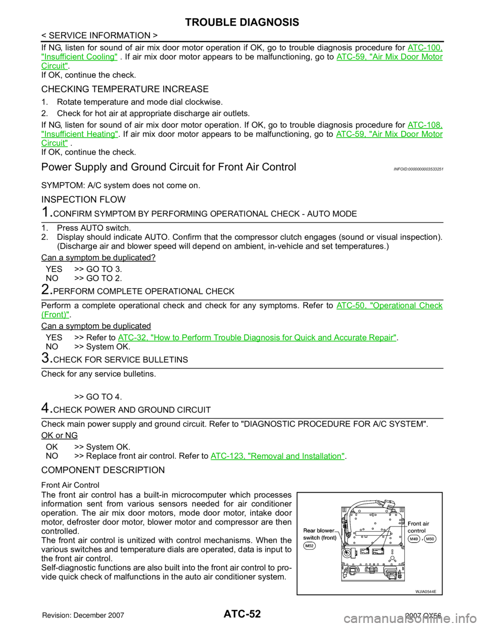
COMPONENT DESCRIPTION
Front Air Control
The front air control has a built-in microcomputer which processes
information sent from various sensors needed for air conditioner
operation. The air mix door motors, mode door motor, intake door
motor, defroster door motor, blower motor and compressor are then
controlled.
The front air control is unitized with control mechanisms. When the
various switches and temperature dials are operated, data is input to
the front air control.
Self-diagnostic functions are also built into the front air control to pro-
vide quick check of malfunctions in the auto air conditioner system.
WJIA0544E
Page 429 of 3061

TROUBLE DIAGNOSISATC-59
< SERVICE INFORMATION >
C
DE
F
G H
I
K L
M A
B
AT C
N
O P
1. Turn ignition switch OFF.
2. Disconnect front air control harness connector.
3. Check continuity between front air control harness connector
M49 terminal 16 and ground.
OK or NG
OK >> Replace front air control. Refer to ATC-123, "Removal
and Installation" .
NG >> Repair or replace harness as necessary.
12.CHECK PBR FEEDBACK CIRCUIT FOR OPEN
1. Turn ignition switch OFF.
2. Disconnect the mode door motor harness connector and front air control harness connector.
3. Check continuity between mode door motor harness connector M142 terminal 2 and front air control harness connector M49 ter-
minal 16.
OK or NG
OK >> Replace mode door motor. Refer to ATC-140, "Removal
and Installation".
NG >> Repair or replace harness as necessary.
Air Mix Door Motor CircuitINFOID:0000000003533253
SYMPTOM:• Discharge air temperature does not change.
• Air mix door motor does not operate.
INSPECTION FLOW
1.CONFIRM SYMPTOM BY PERFORMING OPERAT IONAL CHECK - TEMPERATURE INCREASE
1. Turn the temperature control dial (driver) clockwise until 32 °C (90 °F) is displayed.
2. Check for hot air at discharge air outlets.
>> GO TO 2.
2.CONFIRM SYMPTOM BY PERFORMING OPERAT IONAL CHECK - TEMPERATURE DECREASE
1. Turn the temperature control dial (driver) counterclockwise until 16 °C (60 °F) is displayed.
2. Check for cold air at discharge air outlets.
Can a symptom be duplicated?
YES >> GO TO 4.
NO >> GO TO 3.
3.PERFORM COMPLETE OPERATIONAL CHECK
Perform a complete operational check and check for any symptoms. Refer to ATC-50, "
Operational Check
(Front)" .
Can a symptom be duplicated?
YES >> Refer to ATC-32, "How to Perform Trouble Diagnosis for Quick and Accurate Repair" .
NO >> System OK.
4.CHECK FOR SERVICE BULLETINS
Check for any service bulletins.
>> GO TO 5.
Continuity should not exist.
WJIA1733E
Continuity should exist.
LJIA0034E
Page 464 of 3061

ATC-94
< SERVICE INFORMATION >
TROUBLE DIAGNOSIS
2. Turn the rear blower motor on (1-4 speed).
3. Turn the rear temperature/mode control dial clockwise.
4. Check for hot air at rear foot discharge air outlets.>> GO TO 2.
2.CONFIRM SYMPTOM BY PERFORMING OPER ATIONAL CHECK - TEMPERATURE DECREASE
1. Turn the rear temperature/mode control dial counterclockwise.
2. Check for cold air at rear vent discharge air outlets.
OK or NG?
YES >> GO TO 3.
NO >> GO TO 4.
3.CHECK FOR ANY SYMPTOMS
Perform a complete operational check for any symptoms. Refer to ATC-50, "
Operational Check (Front)" .
Does another symptom exist?
YES >> Refer to ATC-32, "How to Perform Trouble Diagnosis for Quick and Accurate Repair" .
NO >> System OK.
4.CHECK FOR SERVICE BULLETINS
Check for any service bulletins.
>> GO TO 5.
5.PERFORM SELF-DIAGNOSIS
Perform self-diagnosis to check for any codes. Refer to ATC-48, "
A/C System Self-Diagnosis Function" .
Are any self-diagnosis codes present?
YES >> Refer to ATC-48, "A/C System Self-Diagnosis Function".
NO >> GO TO 6.
6.CHECK REAR TEMPERATURE/MODE CONTROL DIAL OPERATION
Check and verify rear outlet position and temperat ure change when adjusted from front air control.
OK or NG?
YES >> Check rear air control circuit. Refer to "DIAGNOSTIC PROCEDURE FOR REAR AIR CONTROL".
NO >> Check air mix door motor (rear). Refer to ATC-59, "
Air Mix Door Motor Circuit" .
SYSTEM DESCRIPTION
Component Parts
Rear air control system components are:
• Front air control
• Rear air control
• Air mix door motor (rear)
• Rear blower motor relay
• Rear blower motor resistor
• Rear blower motor
Page 478 of 3061
ATC-108
< SERVICE INFORMATION >
TROUBLE DIAGNOSIS
Insufficient Heating
INFOID:0000000003533261
SYMPTOM: Insufficient heating
INSPECTION FLOW
1.CONFIRM SYMPTOM BY PERFORMING OPER ATIONAL CHECK - TEMPERATURE INCREASE
1. Press the AUTO switch.
2. Turn the temperature control dial (driver) clockwise until 32 ° C (90 ° F) is displayed.
3. Check for hot air at discharge air outlets.
Can this symptom be duplicated?
YES >> GO TO 2.
NO >> Perform complete system operational check. Refer to ATC-50, "
Operational Check (Front)" .
2.CHECK FOR SERVICE BULLETINS
Check for any service bulletins.
>> GO TO 3.
3.PERFORM SELF-DIAGNOSIS
Perform self-diagnosis. Refer to ATC-48, "
A/C System Self-Diagnosis Function" .
OK or NG
OK >> GO TO 4.
NG >> Refer to ATC-48, "
A/C System Self-Diagnosis Function" .
4.CHECK ENGINE COOLING SYSTEM
1. Check for proper engine coolant level. Refer to CO-9, "
Inspection".
2. Check hoses for leaks or kinks.
3. Check radiator cap. Refer to CO-9, "
Inspection" .
4. Check for air in cooling system.
>> GO TO 5.
5.CHECK AIR MIX DOOR OPERATION
Check the operation of the air mix door.
OK or NG
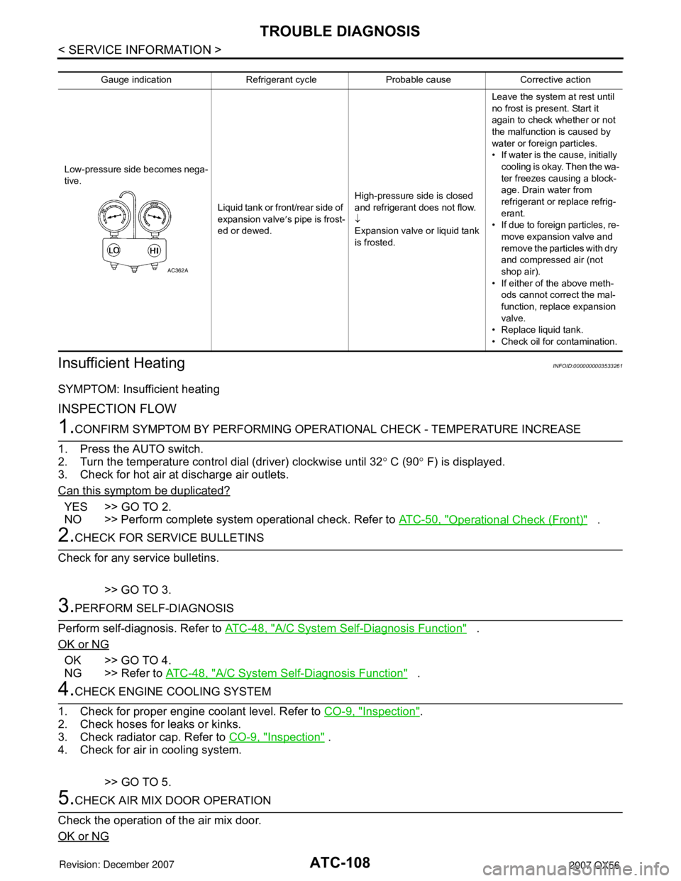
Gauge indication Refrigerant cycle Probable cause Corrective action
Low-pressure side becomes nega-
tive. Liquid tank or front/rear side of
expansion valve′s pipe is frost-
ed or dewed. High-pressure side is closed
and refrigerant does not flow.
↓
Expansion valve or liquid tank
is frosted. Leave the system at rest until
no frost is present. Start it
again to check whether or not
the malfunction is caused by
water or foreign particles.
• If water is the cause, initially
cooling is okay. Then the wa-
ter freezes causing a block-
age. Drain water from
refrigerant or replace refrig-
erant.
• If due to foreign particles, re-
move expansion valve and
remove the particles with dry
and compressed air (not
shop air).
• If either of the above meth- ods cannot correct the mal-
function, replace expansion
valve.
• Replace liquid tank.
• Check oil for contamination.
AC362A
Page 504 of 3061
ATC-134
< SERVICE INFORMATION >
HEATER & COOLING UNIT ASSEMBLY
5. Disconnect the front heater hoses from the front heater core.
6. Disconnect the high/low pressure pipes from the front expansion valve.
7. Remove the instrument panel and console panel. Refer to IP-10, "
Removal and Installation".
8. Remove the steering column. Refer to PS-10
.
9. Disconnect the instrument panel wire harness at the RH and LH in-line connector brackets, and the fuse
block (J/B) electrical connectors. Refer to PG-3
.
10. Disconnect the steering member from each side of the vehicle body.
11. Remove the front heater and cooling unit assembly with it attached to the steering member, from the vehi-
cle.
CAUTION:
Use care not to damage the seats and interior tr im panels when removing the front heater and
cooling unit assembly with it at tached to the steering member.
12. Remove the front heater and cooling unit assembly from the steering member.
Installation
Installation is in the reverse order of removal.
CAUTION:
• Replace the O-ring of the low-pressure pipe and high-pressure pipe with a new one, and apply com-
pressor oil to it when installing it.
• After charging the refrigerant, check for leaks.
NOTE:
• Fill the engine cooling system with the s pecified coolant mixture. Refer to MA-12, "
Changing Engine Cool-
ant".
• Recharge the A/C system. Refer to ATC-150, "
HFC-134a (R-134a) Service Procedure".
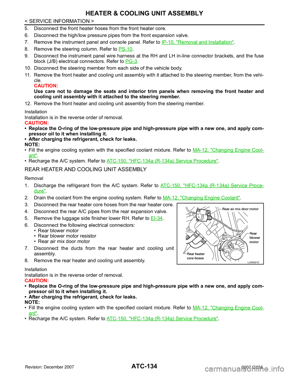
REAR HEATER AND COOLING UNIT ASSEMBLY
Removal
1. Discharge the refrigerant from the A/C system. Refer to ATC-150, "HFC-134a (R-134a) Service Proce-
dure".
2. Drain the coolant from the engine cooling system. Refer to MA-12, "
Changing Engine Coolant".
3. Disconnect the rear heater core hoses from the rear heater core.
4. Disconnect the rear A/C pipes from the rear expansion valve.
5. Remove the luggage side finisher lower RH. Refer to EI-34
.
6. Disconnect the following electrical connectors: • Rear blower motor
• Rear blower motor resistor
• Rear air mix door motor
7. Disconnect the ducts from the rear heater and cooling unit assembly.
8. Remove the rear heater and cooling unit assembly.
Installation
Installation is in the reverse order of removal.
CAUTION:
• Replace the O-ring of the low-pressure pipe and high-pressure pipe with a new one, and apply com-
pressor oil to it when installing it.
• After charging the refrigerant, check for leaks.
NOTE:
• Fill the engine cooling system with the s pecified coolant mixture. Refer to MA-12, "
Changing Engine Cool-
ant".
• Recharge the A/C system. Refer to ATC-150, "
HFC-134a (R-134a) Service Procedure".
LJIA0021E
Page 546 of 3061

AV-6
< SERVICE INFORMATION >
AUDIO
System Description
INFOID:0000000003533664
Refer to Owner's Manual for audio system operating instructions.
Power is supplied at all times
• through 15A fuse [No. 17, located in the fuse block (J/B)]
• to subwoofer terminal 6
• through 20A fuse [No. 31, located in the fuse and fusible link box]
• to audio unit terminal 6
• to BOSE speaker amp. terminal 1
• to AV switch terminal 1 and
• to display control unit terminal 1.
With the ignition switch in the ACC or ON position, power is supplied
• through 10A fuse [No. 4, located in the fuse block (J/B)]
• to audio unit terminal 10 and
• to AV switch terminal 2 and
• to display control unit terminal 10.
With the ignition switch in the ON or START position, power is supplied
• through 10A fuse [No. 12, located in the fuse block (J/B)]
• to display control unit terminal 12.
Ground is supplied through the case of the audio unit.
Ground is also supplied
• to subwoofer terminal 5
• through body grounds B7 and B19 and
• to BOSE speaker amp. terminal 17
• to AV switch terminal 5 and
• to display unit terminal 1 and
• to display control unit terminal 3
• through body grounds M57, M61 and M79.
Then audio signals are supplied
• through audio unit terminals 1, 2, 3, 4, 13, 14, 15 and 16
• to BOSE speaker amp. terminals 23, 24, 25, 26, 27, 28, 29 and 30.
Audio signals are amplified by the BOSE speaker amp.
The amplified audio signals are supplied
• through BOSE speaker amp. terminals 2, 3, 9,10,11,12, 13, 14, 15, 16, 18 and 19
• to terminals + and - of front door speaker LH and RH and
• to terminals + and - of front tweeter LH and RH and
• to terminals + and - of center speaker and
• to terminals + and - of rear door speaker LH and RH and
• to terminals + and - of rear door tweeter LH and RH and
• to terminals 1 and 2 of subwoofer.
When one of steering wheel audio control switches is pushed, the resistance in steering switch circuit changes
depending on which button is pushed.
Rear Audio Remote Control Unit
Power is supplied
• from audio unit terminal 32
• to rear audio remote control unit terminal 13.
Ground is supplied
• to rear audio remote control unit terminal 15
7. Display control unit
M94, M958. Front tweeter RH
M 1119. AV Switch
M98
10. Audio unit
M43, M44, M45, M4611. BOSE speaker amp
M112, M11312. Satellite radio tuner (pre-wiring or factory
installed, if equipped)
M41
13. Steering wheel audio control switches 14. Front door speaker LH, RH
D12, D11215. Rear door tweeter LH, RH
D208, D308
16. Rear door speaker LH, RH
D207, D30717. Driver seat 18. Subwoofer
B72
19. Rear audio remote control unit
R204