4WD INFINITI QX56 2007 Factory Service Manual
[x] Cancel search | Manufacturer: INFINITI, Model Year: 2007, Model line: QX56, Model: INFINITI QX56 2007Pages: 3061, PDF Size: 64.56 MB
Page 2932 of 3061

TF-110
< SERVICE INFORMATION >
TROUBLE DIAGNOSIS FOR SYMPTOMS
- Transfer control unit harness connector E142 terminal 40 and
combination meter harness connector M24 terminal 7.
Also check harness for short to ground and short to power.
OK or NG
OK >> GO TO 6.
NG >> Repair or replace damaged parts.
6.CHECK ATP WARNING LAMP CIRCUIT
1. A/T selector lever in "P" position.
2. Connect combination meter harness connector and transfer control unit harness connector.
3. Disconnect ATP switch harness connector.
4. Ground the following terminal using suitable wiring.
- ATP switch harness connector F55 terminal 8 and ground.
5. Turn ignition switch “ON”. (Do not start engine.)
Does indicator lamp turn on?
OK >> GO TO 7.
NG >> Replace combination meter. Refer to DI-21, "
Removal
and Installation of Combination Meter".
7.SYMPTOM CHECK
Check again.
OK or NG
OK >> Inspection End.
NG >> GO TO 8.
8.CHECK TRANSFER CONTROL UNIT
Check transfer control unit input/output signal. Refer to TF-35, "
Transfer Control Unit Input/Output Signal Ref-
erence Value".
OK or NG
OK >> GO TO 9.
NG >> Check transfer control unit pin terminals for damage or loose connection with harness connector.
If any items are damaged, repair or replace damaged parts.
9.CHECK TRANSFER INNER PARTS
1. Disassemble transfer assembly. Refer to TF-128, "
Disassembly and Assembly".
2. Check transfer inner parts.
OK or NG
OK >> Inspection End.
NG >> Repair or replace damaged parts.
4LO Indicator Lamp Repeats FlashingINFOID:0000000003532557
SYMPTOM:
4LO lamp keeps flashing.
DIAGNOSTIC PROCEDURE
1.CONFIRM THE SYMPTOM
1. Set 4WD shift switch to “2WD”.
2. Move vehicle forward and backward, or drive straight increasing or decreasing under 20 km/h (12 MPH). 40 to 7: Continuity should not exist.
7 to 40: Continuity should exist.
WDIA0150E
SDIA2769E
Page 2933 of 3061

TROUBLE DIAGNOSIS FOR SYMPTOMS
TF-111
< SERVICE INFORMATION >
C
E
F
G
H
I
J
K
L
MA
B
TF
N
O
P
Dose 4WD shift indicator lamp keep flashing?
YES >> GO TO 2.
NO >> Inspection End.
2.CHECK SYSTEM FOR WAIT DETECTION SWITCH
Perform trouble diagnosis for wait detection switch system. Refer to TF-60, "
Wait Detection Switch".
OK or NG
OK >> GO TO 3.
NG >> Repair or replace damaged parts.
3.CHECK SYSTEM FOR NEUTRAL-4LO SWITCH
Perform trouble diagnosis for neutral-4LO switch system. Refer to TF-54, "
Neutral-4LO Switch".
OK or NG
OK >> GO TO 4.
NG >> Repair or replace damaged parts.
4.SYMPTOM CHECK
Check again.
OK or NG
OK >> Inspection End.
NG >> GO TO 5.
5.CHECK TRANSFER CONTROL UNIT
Check transfer control unit input/output signal. Refer to TF-35, "
Transfer Control Unit Input/Output Signal Ref-
erence Value".
OK or NG
OK >> GO TO 6.
NG >> Check transfer control unit pin terminals for damage or loose connection with harness connector.
If any items are damaged, repair or replace damaged parts.
6.CHECK TRANSFER INNER PARTS
1. Disassemble transfer assembly. Refer to TF-128, "
Disassembly and Assembly".
2. Check transfer inner parts.
OK or NG
OK >> Inspection End.
NG >> Repair or replace damaged parts.
4WD Warning Lamp Flashes RapidlyINFOID:0000000003532558
SYMPTOM:
While driving, 4WD warning lamp flashes rapidly.
NOTE:
Rapid flashing: 2 times/second
DIAGNOSTIC PROCEDURE
1.CHECK TIRE
Check the following.
• Tire pressure
• Wear condition
• Longitudinal tire size (There is no difference between longitudinal tires.)
OK or NG
OK >> GO TO 2.
NG >> Repair or replace damaged parts.
2.CHECK 4WD WARNING LAMP
Stop the vehicle and allow it to idle for a short period of time.
Does flashing stop?
Page 2934 of 3061

TF-112
< SERVICE INFORMATION >
TROUBLE DIAGNOSIS FOR SYMPTOMS
YES >> Inspection End.
NO >> GO TO 3.
3.CHECK TRANSFER FLUID TEMPERATURE
Perform trouble diagnosis for transfer fluid temperature system. Refer to TF-90, "
Transfer Fluid Temperature".
OK or NG
OK >> GO TO 4.
NG >> Repair or replace damaged parts.
4.SYMPTOM CHECK
Check again.
OK or NG
OK >> Inspection End.
NG >> GO TO 5.
5.CHECK TRANSFER CONTROL UNIT
Check transfer control unit input/output signal. Refer to TF-35, "
Transfer Control Unit Input/Output Signal Ref-
erence Value".
OK or NG
OK >> Inspection End.
NG >> Check transfer control unit pin terminals for damage or loose connection with harness connector.
If any items are damaged, repair or replace damaged parts.
4WD Warning Lamp Flashes SlowlyINFOID:0000000003532559
SYMPTOM:
While driving, 4WD warning lamp flashes slowly. (When continuing to flash until turning ignition
switch OFF.)
NOTE:
Slow flashing: 1 time/2 seconds
DIAGNOSTIC PROCEDURE
1.CHECK TIRE
Check the following.
• Tire pressure
• Wear condition
• Longitudinal tire size (There is no difference between longitudinal tires.)
OK or NG
OK >> GO TO 2.
NG >> Repair or replace damaged parts.
2.CHECK TRANSFER FLUID TEMPERATURE
Perform trouble diagnosis for transfer fluid temperature system. Refer to TF-90, "
Transfer Fluid Temperature".
OK or NG
OK >> GO TO 3.
NG >> Repair or replace damaged parts.
3.CHECK CLUTCH PRESSURE SWITCH
Perform trouble diagnosis for clutch pressure switch system. Refer to TF-92, "
Clutch Pressure Switch".
OK or NG
OK >> GO TO 4.
NG >> Repair or replace damaged parts.
4.SYMPTOM CHECK
Check again.
OK or NG
OK >> Inspection End.
Page 2935 of 3061

TROUBLE DIAGNOSIS FOR SYMPTOMS
TF-113
< SERVICE INFORMATION >
C
E
F
G
H
I
J
K
L
MA
B
TF
N
O
P
NG >> GO TO 5.
5.CHECK TRANSFER CONTROL UNIT
Check transfer control unit input/output signal. Refer to TF-35, "
Transfer Control Unit Input/Output Signal Ref-
erence Value".
OK or NG
OK >> Inspection End.
NG >> Check transfer control unit pin terminals for damage or loose connection with harness connector.
If any items are damaged, repair or replace damaged parts.
Heavy Tight-corner Braking Symptom OccursINFOID:0000000003532560
SYMPTOM:
Heavy tight-corner braking symptom occurs when vehicle is driven in AUTO mode and steering wheel
is turned fully to either side.
DIAGNOSTIC PROCEDURE
NOTE:
• Light tight-corner braking symptom may occur depending on driving conditions in AUTO mode. This is not a
malfunction.
• Heavy tight-corner braking symptom occurs when vehicle is driven in the following conditions: 4WD shift
switch is "4H" or "4LO", steering wheel is turned fully to either side.
1.CHECK SYSTEM FOR CAN COMMUNICATION LINE
Perform self-diagnosis. Refer to TF-48, "
Self-Diagnosis Procedure".
Is "CAN COMM CIRCUIT [U1000]" displayed?
YES >> Perform trouble diagnosis for CAN communication line. Refer to TF-99, "CAN Communication
Line" .
NO >> GO TO 2.
2.CHECK SYSTEM FOR 4WD SHIFT SWITCH
Perform trouble diagnosis for 4WD shift switch system. Refer to TF-57, "
4WD Shift Switch".
OK or NG
OK >> GO TO 3.
NG >> Repair or replace damaged parts.
3.CHECK ACCELERATOR PEDAL POSITION SIGNAL CIRCUIT
Perform self diagnosis for ECM. Refer to E C - 111 , "
CONSULT-II Function (ENGINE)".
Is any malfunction deteced by self-diagnosis?
YES >> Check the malfunctioning system.
NO >> GO TO 4.
4.CHECK SYSTEM FOR CLUTCH PRESSURE SOLENOID
Perform trouble diagnosis for clutch pressure solenoid system. Refer toTF-92, "
Clutch Pressure Switch" .
OK or NG
OK >> GO TO 5.
NG >> Repair or replace damaged parts.
5.SYMPTOM CHECK
Check again.
OK or NG
OK >> Inspection End.
NG >> GO TO 6.
6.CHECK TRANSFER CONTROL UNIT
Check transfer control unit input/output signal. Refer to TF-35, "
Transfer Control Unit Input/Output Signal Ref-
erence Value".
OK or NG
Page 2936 of 3061

TF-114
< SERVICE INFORMATION >
TROUBLE DIAGNOSIS FOR SYMPTOMS
OK >> GO TO 7.
NG >> Check transfer control unit pin terminals for damage or loose connection with harness connector.
If any items are damaged, repair or replace damaged parts.
7.CHECK TRANSFER INNER PARTS
1. Disassemble transfer assembly. Refer to TF-128, "
Disassembly and Assembly".
2. Check transfer inner parts.
OK or NG
OK >> Inspection End.
NG >> Repair or replace damaged parts.
4WD System Does Not OperateINFOID:0000000003532561
SYMPTOM:
The vehicle cannot be put into 4WD mode. (Hydraulic system failure)
DIAGNOSTIC PROCEDURE
1.CHECK SYSTEM FOR 4WD SHIFT SWITCH
Perform trouble diagnosis for 4WD shift switch system. Refer to TF-57, "
4WD Shift Switch".
OK or NG
OK >> GO TO 2.
NG >> Repair or replace damaged parts.
2.CHECK SYSTEM FOR CLUTCH PRESSURE SWITCH
Perform trouble diagnosis for clutch pressure switch system. Refer to TF-92, "
Clutch Pressure Switch".
OK or NG
OK >> GO TO 3.
NG >> Repair or replace damaged parts.
3.SYMPTOM CHECK
Check again.
OK or NG
OK >> Inspection End.
NG >> GO TO 4.
4.CHECK TRANSFER CONTROL UNIT
Check transfer control unit input/output signal. Refer to TF-35, "
Transfer Control Unit Input/Output Signal Ref-
erence Value".
OK or NG
OK >> GO TO 5.
NG >> Check transfer control unit pin terminals for damage or loose connection with harness connector.
If any items are damaged, repair or replace damaged parts.
5.CHECK TRANSFER INNER PARTS
1. Disassemble transfer assembly. Refer to TF-128, "
Disassembly and Assembly".
2. Check transfer inner parts.
OK or NG
OK >> Inspection End.
NG >> Repair or replace damaged parts.
Page 2937 of 3061

TRANSFER CONTROL UNIT
TF-115
< SERVICE INFORMATION >
C
E
F
G
H
I
J
K
L
MA
B
TF
N
O
P
TRANSFER CONTROL UNIT
Removal and InstallationINFOID:0000000003532562
REMOVAL
1. Set transfer state as 2WD when 4WD shift switch is at 2WD, or as AUTO when 4WD shift switch is at
AUTO.
CAUTION:
When removing transfer control unit, transfer state must be at 2WD or AUTO.
2. Turn the ignition switch OFF and disconnect negative battery terminal.
3. Remove the glove box assembly. Refer to IP-10, "
Removal and Installation".
4. Disconnect the two transfer control unit connectors.
5. Remove the transfer control unit bolts.
6. Remove the transfer control unit.
INSTALLATION
Installation is in the reverse order of removal.
• When installing the transfer control unit, tighten bolts to the specified torque.
CAUTION:
• Do not connect harness connector to transfer control unit when 4WD shift switch is at 4LO.
• After the installation, check perform self-diagnosis. Refer to TF-48, "
Self-Diagnosis Procedure". If NG, adjust
position between transfer assembly and transfer control unit. Refer to TF-3, "
Precaution for Transfer Assem-
bly and Transfer Control Unit Replacement".
BDIA0014E
Transfer control unit bolts : 5.1 N·m (0.52 kg-m, 45 in-lb)
Page 2943 of 3061

TRANSFER CONTROL DEVICE
TF-121
< SERVICE INFORMATION >
C
E
F
G
H
I
J
K
L
MA
B
TF
N
O
P
TRANSFER CONTROL DEVICE
Removal and InstallationINFOID:0000000003532566
CAUTION:
• Change vehicle state to 2WD, and then remove and install transfer control device.
• Check 4WD shift indicator after installation. Refer to TF-3, "
Precaution for Transfer Assembly and
Transfer Control Unit Replacement".
1. Shift lever 2. Transfer control device
SDIA2654E
Page 2965 of 3061

TRANSFER ASSEMBLY
TF-143
< SERVICE INFORMATION >
C
E
F
G
H
I
J
K
L
MA
B
TF
N
O
P
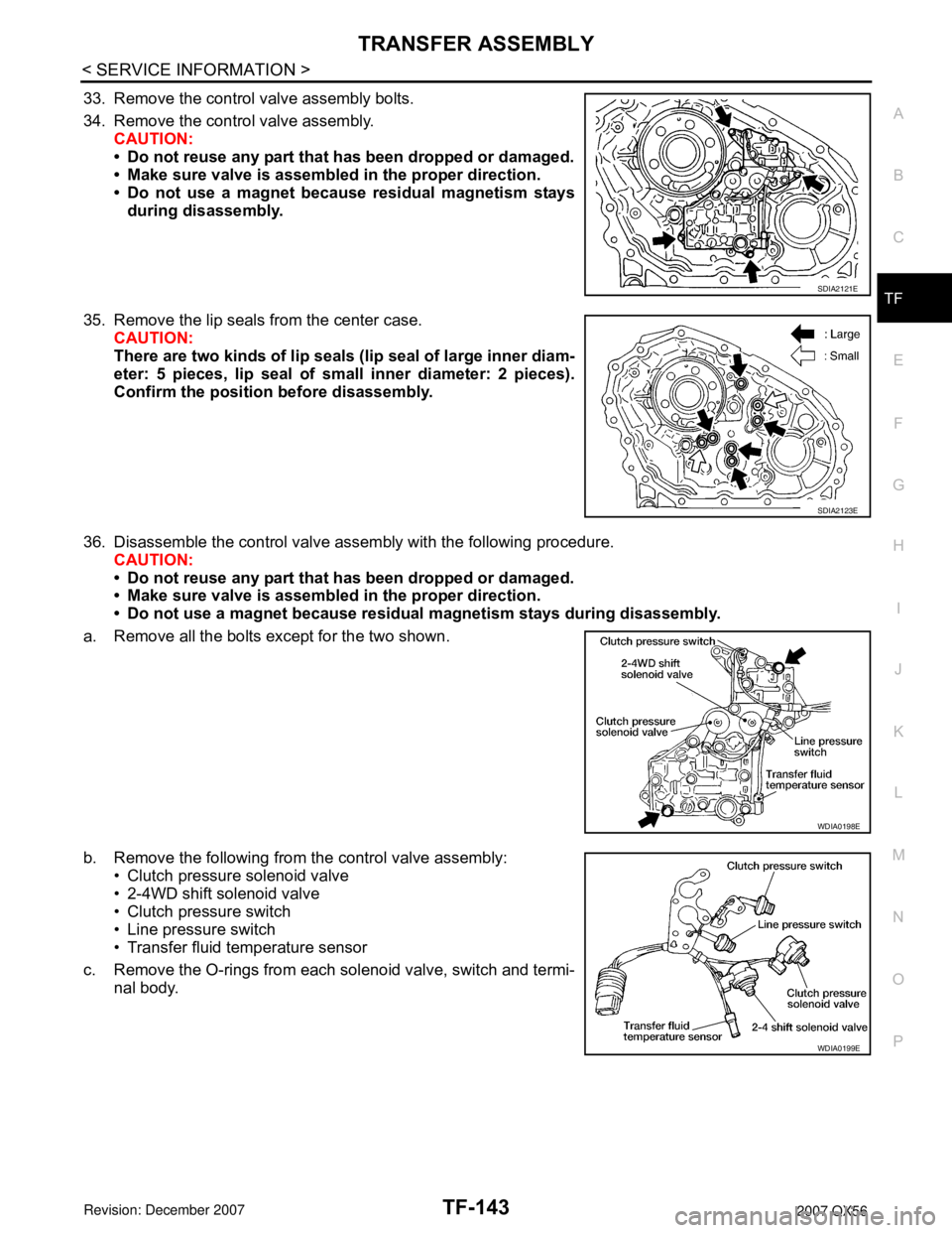
33. Remove the control valve assembly bolts.
34. Remove the control valve assembly.
CAUTION:
• Do not reuse any part that has been dropped or damaged.
• Make sure valve is assembled in the proper direction.
• Do not use a magnet because residual magnetism stays
during disassembly.
35. Remove the lip seals from the center case.
CAUTION:
There are two kinds of lip seals (lip seal of large inner diam-
eter: 5 pieces, lip seal of small inner diameter: 2 pieces).
Confirm the position before disassembly.
36. Disassemble the control valve assembly with the following procedure.
CAUTION:
• Do not reuse any part that has been dropped or damaged.
• Make sure valve is assembled in the proper direction.
• Do not use a magnet because residual magnetism stays during disassembly.
a. Remove all the bolts except for the two shown.
b. Remove the following from the control valve assembly:
• Clutch pressure solenoid valve
• 2-4WD shift solenoid valve
• Clutch pressure switch
• Line pressure switch
• Transfer fluid temperature sensor
c. Remove the O-rings from each solenoid valve, switch and termi-
nal body.
SDIA2121E
SDIA2123E
WDIA0198E
WDIA0199E
Page 2970 of 3061

TF-148
< SERVICE INFORMATION >
TRANSFER ASSEMBLY
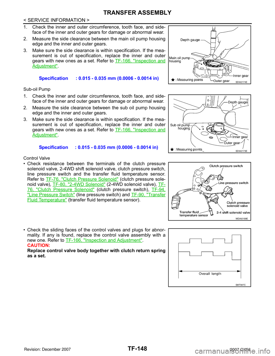
1. Check the inner and outer circumference, tooth face, and side-
face of the inner and outer gears for damage or abnormal wear.
2. Measure the side clearance between the main oil pump housing
edge and the inner and outer gears.
3. Make sure the side clearance is within specification. If the mea-
surement is out of specification, replace the inner and outer
gears with new ones as a set. Refer to TF-166, "
Inspection and
Adjustment".
Sub-oil Pump
1. Check the inner and outer circumference, tooth face, and side-
face of the inner and outer gears for damage or abnormal wear.
2. Measure the side clearance between the sub oil pump housing
edge and the inner and outer gears.
3. Make sure the side clearance is within specification. If the mea-
surement is out of specification, replace the inner and outer
gears with new ones as a set. Refer to TF-166, "
Inspection and
Adjustment".
Control Valve
• Check resistance between the terminals of the clutch pressure
solenoid valve, 2-4WD shift solenoid valve, clutch pressure switch,
line pressure switch and the transfer fluid temperature sensor.
Refer to TF-76, "
Clutch Pressure Solenoid" (clutch pressure sole-
noid valve), TF-80, "
2-4WD Solenoid" (2-4WD solenoid valve), TF-
76, "Clutch Pressure Solenoid" (clutch pressure switch), TF-94,
"Line Pressure Switch" (line pressure switch) and TF-90, "Transfer
Fluid Temperature" (transfer fluid temperature sensor).
• Check the sliding faces of the control valves and plugs for abnor-
mality. If any is found, replace the control valve assembly with a
new one. Refer to TF-166, "
Inspection and Adjustment".
CAUTION:
Replace control valve body together with clutch return spring
as a set.Specification : 0.015 - 0.035 mm (0.0006 - 0.0014 in)
SDIA2174E
Specification : 0.015 - 0.035 mm (0.0006 - 0.0014 in)SDIA2173E
WDIA0199E
SMT947C
Page 2974 of 3061

TF-152
< SERVICE INFORMATION >
TRANSFER ASSEMBLY
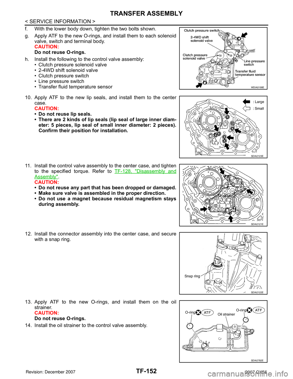
f. With the lower body down, tighten the two bolts shown.
g. Apply ATF to the new O-rings, and install them to each solenoid
valve, switch and terminal body.
CAUTION:
Do not reuse O-rings.
h. Install the following to the control valve assembly:
• Clutch pressure solenoid valve
• 2-4WD shift solenoid valve
• Clutch pressure switch
• Line pressure switch
• Transfer fluid temperature sensor
10. Apply ATF to the new lip seals, and install them to the center
case.
CAUTION:
• Do not reuse lip seals.
• There are 2 kinds of lip seals (lip seal of large inner diam-
eter: 5 pieces, lip seal of small inner diameter: 2 pieces).
Confirm their position for installation.
11. Install the control valve assembly to the center case, and tighten
to the specified torque. Refer to TF-128, "
Disassembly and
Assembly".
CAUTION:
• Do not reuse any part that has been dropped or damaged.
• Make sure valve is assembled in the proper direction.
• Do not use a magnet because residual magnetism stays
during assembly.
12. Install the connector assembly into the center case, and secure
with a snap ring.
13. Apply ATF to the new O-rings, and install them on the oil
strainer.
CAUTION:
Do not reuse O-rings.
14. Install the oil strainer to the control valve assembly.
WDIA0198E
SDIA2123E
SDIA2121E
SDIA2122E
SDIA2782E