light INFINITI QX56 2007 Factory Service Manual
[x] Cancel search | Manufacturer: INFINITI, Model Year: 2007, Model line: QX56, Model: INFINITI QX56 2007Pages: 3061, PDF Size: 64.56 MB
Page 1 of 3061

-1
QUICK REFERENCE INDEX
AGENERAL INFORMATIONGIGeneral Information
BENGINEEMEngine Mechanical
LUEngine Lubrication System
COEngine Cooling System
ECEngine Control System
FLFuel System
EXExhaust System
ACCAccelerator Control System
CTRANSMISSION/
TRANSAXLEATAutomatic Transmission
DDRIVELINE/AXLETFTransfer
PRPropeller Shaft
FFDFront Final Drive
RFDRear Final Drive
FAXFront Axle
RAXRear Axle
ESUSPENSIONFSUFront Suspension
RSURear Suspension
WTRoad Wheels & Tires
FBRAKESBRBrake System
PBParking Brake System
BRCBrake Control System
GSTEERINGPSPower Steering System
HRESTRAINTSSBSeat Belts
SRSSupplemental Restraint System (SRS)
IBODYBLBody, Lock & Security System
GWGlasses, Window System & Mirrors
RFRoof
EIExterior & Interior
IPInstrument Panel
SESeat
APAdjustable Pedal
JAIR CONDITIONERATCAutomatic Air Conditioner
KELECTRICALSCStarting & Charging System
LTLighting System
DIDriver Information System
WWWiper, Washer & Horn
BCSBody Control System
LANLAN System
AVAudio Visual, Navigation & Telephone System
ACSAuto Cruise Control System
PGPower Supply, Ground & Circuit Elements
LMAINTENANCEMAMaintenance
Edition: August 2006
Revision: December 2007
Publication No. SM7E-1J60U1
B
D
© 2007 NISSAN NORTH AMERICA, INC.
All rights reserved. No part of this Service Manual may be reproduced or stored in a retrieval system, or transmitted in any
form, or by any means, electronic, mechanical, photo-copying, recording or otherwise, without the prior written permission
of Nissan North America, Inc.
A
C
E
F
G
H
I
J
K
L
M
Page 19 of 3061
![INFINITI QX56 2007 Factory Service Manual ACS-6
< SERVICE INFORMATION >[ICC]
DESCRIPTION
DESCRIPTION
OutlineINFOID:0000000003533775
The Intelligent Cruise Control (ICC) system automatically maintains a selected distance from the vehicle
ahead INFINITI QX56 2007 Factory Service Manual ACS-6
< SERVICE INFORMATION >[ICC]
DESCRIPTION
DESCRIPTION
OutlineINFOID:0000000003533775
The Intelligent Cruise Control (ICC) system automatically maintains a selected distance from the vehicle
ahead](/img/42/57029/w960_57029-18.png)
ACS-6
< SERVICE INFORMATION >[ICC]
DESCRIPTION
DESCRIPTION
OutlineINFOID:0000000003533775
The Intelligent Cruise Control (ICC) system automatically maintains a selected distance from the vehicle
ahead according to that vehicle's speed, or at the set speed, if the road ahead is clear.
The ICC function has two cruise control modes and brake assist (with preview function). The ICC system may
AUTO-CANCEL for various reasons, for example, when the windshield wipers are operating.
VEHICLE-TO-VEHICLE DISTANCE CONTROL MODE
Vehicle-to-vehicle distance control mode, the same speed as other vehicles, can be maintained without the
constant need to adjust the operating speed as with a conventional cruise control system.
The system is intended to enhance the operation of the vehicle when following another vehicle in the same
lane and direction.
If the distance sensor detects a slower moving vehicle ahead, the system will reduce speed so that the vehicle
ahead can be followed at the selected distance.
The system automatically controls the throttle and applies the brakes (up to 25% of vehicle braking power) if
necessary.
The detection range of the sensor is approximately 120 m (390 ft) ahead.
Refer to Owner's Manual for Intelligent Cruise Control System operating instructions.
CONVENTIONAL (FIXED SPEED) CRUISE CONTROL MODE
Conventional (fixed speed) cruise control mode is cruising at preset speeds.
Refer to Owner's Manual for Intelligent Cruise Control System operation instructions.
BRAKE ASSIST (WITH PREVIEW FUNCTION)
When the force applied to brake pedal exceeds a certain level, the brake assist is activated and generates a
greater braking force than that of a conventional brake booster, even with light pedal force.
When the preview function identifies the need to apply the sudden brake by sensing the vehicle ahead in the
same lane and the distance and relative speed from it, it applies the brake pre-pressure before driver
depresses the brake pedal and improves brake response by reducing its free play.
Refer to Owner's Manual for Intelligent Cruise Control System operating instructions.
SchematicINFOID:0000000003533776
WKIA1976E
Page 21 of 3061
![INFINITI QX56 2007 Factory Service Manual ACS-8
< SERVICE INFORMATION >[ICC]
DESCRIPTION
ICC System Display
INFOID:0000000003533780
4 CANCEL switch Deactivates system without erasing set speed.
5 DISTANCE switch Changes the following distance INFINITI QX56 2007 Factory Service Manual ACS-8
< SERVICE INFORMATION >[ICC]
DESCRIPTION
ICC System Display
INFOID:0000000003533780
4 CANCEL switch Deactivates system without erasing set speed.
5 DISTANCE switch Changes the following distance](/img/42/57029/w960_57029-20.png)
ACS-8
< SERVICE INFORMATION >[ICC]
DESCRIPTION
ICC System Display
INFOID:0000000003533780
4 CANCEL switch Deactivates system without erasing set speed.
5 DISTANCE switch Changes the following distance from: Long, Middle, Short. No. Switch name Description
WKIA1977E
No. Component Description
1 Set vehicle speed indicator Indicates the set vehicle speed.
2 Vehicle ahead detection indicator Indicates whether it detects a vehicle ahead.
3 Set distance indicatorDisplay the selected distance between vehicles set with the DISTANCE
switch.
4 Own vehicle indicator Indicates the base vehicle.
5 ON/OFF switch indicator lamp (Green) Indicates that the system is ON.
6Intelligent cruise control system warning
lamp (Orange)The light comes on if there is a malfunction in the ICC system.
7 Cruise set switch indicator lamp Indicates that the conventional cruise control mode is on.
Page 27 of 3061
![INFINITI QX56 2007 Factory Service Manual ACS-14
< SERVICE INFORMATION >[ICC]
LASER BEAM AIMING ADJUSTMENT
4. Pivot the target board on its center mark 20° to either side.
NOTE:
Approx. 50 mm (1.97 in) shift will produce a 20° movement.
5. INFINITI QX56 2007 Factory Service Manual ACS-14
< SERVICE INFORMATION >[ICC]
LASER BEAM AIMING ADJUSTMENT
4. Pivot the target board on its center mark 20° to either side.
NOTE:
Approx. 50 mm (1.97 in) shift will produce a 20° movement.
5.](/img/42/57029/w960_57029-26.png)
ACS-14
< SERVICE INFORMATION >[ICC]
LASER BEAM AIMING ADJUSTMENT
4. Pivot the target board on its center mark 20° to either side.
NOTE:
Approx. 50 mm (1.97 in) shift will produce a 20° movement.
5. Remove any items in the shaded space shown in the figure.
NOTE:
In case the background space shown in the illustration is not available, or if the background is light col-
ored, place a 400 mm (15.75 in) long frosted black board or black cloth to both sides of the target board.
Sensor AdjustmentINFOID:0000000003533785
CAUTION:
• Complete all necessary steps for laser beam adjustment until the CONSULT-II indicates "COM-
PLETED". If the procedure does not complete, the ICC system is inoperable.
• If CONSULT-II is used without connection to the CONSULT-II CONVERTER, malfunctions might be
detected during self-diagnosis.
1. Turn ignition switch OFF.
2. Connect CONSULT-II and CONSULT-II CONVERTER to the
data link connector.
PKIA2589E
WKIA1858E
BBIA0369E
Page 39 of 3061
![INFINITI QX56 2007 Factory Service Manual ACS-26
< SERVICE INFORMATION >[ICC]
TROUBLE DIAGNOSIS — GENERAL DESCRIPTION
CONSULT-II START PROCEDURE
Refer to GI-36, "CONSULT-II Start Procedure".
WORK SUPPORT
Work Item
Cause of Auto-Cancel
1. To INFINITI QX56 2007 Factory Service Manual ACS-26
< SERVICE INFORMATION >[ICC]
TROUBLE DIAGNOSIS — GENERAL DESCRIPTION
CONSULT-II START PROCEDURE
Refer to GI-36, "CONSULT-II Start Procedure".
WORK SUPPORT
Work Item
Cause of Auto-Cancel
1. To](/img/42/57029/w960_57029-38.png)
ACS-26
< SERVICE INFORMATION >[ICC]
TROUBLE DIAGNOSIS — GENERAL DESCRIPTION
CONSULT-II START PROCEDURE
Refer to GI-36, "CONSULT-II Start Procedure".
WORK SUPPORT
Work Item
Cause of Auto-Cancel
1. Touch “WORK SUPPORT” on "SELECT DIAG MODE" screen.
2. Touch “CAUSE OF AUTO-CANCEL” on "SELECT WORK ITEM"
screen.
3. Cause of automatic cancellation screen will be shown.
4. The last five causes of automatic cancellation of ICC system will
be displayed.
Possible Causes of "Auto-Cancel"
Laser Beam Adjust
For details, refer to ACS-12 .
SELF-DIAGNOSTIC RESULTS
For details, refer to ACS-34, "Diagnostic Trouble Code (DTC) Chart" .
DATA MONITOR
CAN DIAG SUPPORT MNTR The results of transmit/receive diagnosis of CAN communication can be read.
ACTIVE TEST Operation of electrical loads can be checked by sending driving signal to them.
ECU PART NUMBER ICC unit part number can be read.ICC diagnostic mode Description
Operation Function
CAUSE OF AUTO-CANCEL Indicates causes of automatic cancellation of the ICC system.
LASER BEAM ADJUST Outputs laser beam, calculates dislocation of the beam, and indicates adjustment direction.
SKIA6191E
Cause of cancellation Description
OPERATING WIPER Windshield wipers were operated at HI or LO speed operation.
OPERATING ABS ABS function was operated.
OPERATING TCS TCS function was operated.
OPERATING VDC VDC function was operated.
ECM CIRCUIT ECM did not permit ICC operation.
OPE SW VOLT CIRC Voltage outside the standard was detected.
LASER SUN BEAM Intense light such as sunlight entered ICC sensor light sensing part.
LASER TEMP Temperature around ICC sensor became low.
WHL SPD ELEC NOISE Wheel speed sensor signal caught electromagnetic noise.
OP SW DOUBLE TOUCH ICC steering switches were pressed at the same time.
VDC/TCS OFF SW VDC OFF switch was pressed.
WHEEL SPD UNMATCH Wheel speed became different from AT vehicle speed.
TIRE SLIP Wheel slipped.
PKB SW ON Parking brake is applied.
IGN LOW VOLT Power supply voltage became low.
NO RECORD—
Page 78 of 3061

AT-8
< SERVICE INFORMATION >
PRECAUTIONS
PRECAUTIONS
Precaution for Supplemental Restraint System (SRS) "AIR BAG" and "SEAT BELT
PRE-TENSIONER"
INFOID:0000000003532218
The Supplemental Restraint System such as “AIR BAG” and “SEAT BELT PRE-TENSIONER”, used along
with a front seat belt, helps to reduce the risk or severity of injury to the driver and front passenger for certain
types of collision. This system includes seat belt switch inputs and dual stage front air bag modules. The SRS
system uses the seat belt switches to determine the front air bag deployment, and may only deploy one front
air bag, depending on the severity of a collision and whether the front occupants are belted or unbelted.
Information necessary to service the system safely is included in the SRS and SB section of this Service Man-
ual.
WARNING:
• To avoid rendering the SRS inoperative, which could increase the risk of personal injury or death in
the event of a collision which would result in air bag inflation, all maintenance must be performed by
an authorized NISSAN/INFINITI dealer.
• Improper maintenance, including incorrect removal and installation of the SRS, can lead to personal
injury caused by unintentional activation of the system. For removal of Spiral Cable and Air Bag
Module, see the SRS section.
• Do not use electrical test equipment on any circuit related to the SRS unless instructed to in this
Service Manual. SRS wiring harnesses can be identified by yellow and/or orange harnesses or har-
ness connectors.
Precaution for On Board Diagnosis (OBD) System of A/T and EngineINFOID:0000000003532219
The ECM has an on board diagnostic system. It will light up the malfunction indicator lamp (MIL) to warn the
driver of a malfunction causing emission deterioration.
CAUTION:
• Be sure to turn the ignition switch “OFF” and disconnect the negative battery cable before any repair
or inspection work. The open/short circuit of related switches, sensors, solenoid valves, etc. Will
cause the MIL to light up.
• Be sure to connect and lock the connectors securely after work. A loose (unlocked) connector will
cause the MIL to light up due to an open circuit. (Be sure the connector is free from water, grease,
dirt, bent terminals, etc.)
• Be sure to route and secure the harnesses properly after work. Interference of the harness with a
bracket, etc. May cause the MIL to light up due to a short circuit.
• Be sure to connect rubber tubes properly after work. A misconnected or disconnected rubber tube
may cause the MIL to light up due to a malfunction of the EGR system or fuel injection system, etc.
• Be sure to erase the unnecessary malfunction information (repairs completed) from the TCM and
ECM before returning the vehicle to the customer.
PrecautionINFOID:0000000003532220
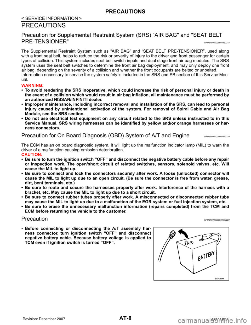
•Before connecting or disconnecting the A/T assembly har-
ness connector, turn ignition switch “OFF” and disconnect
negative battery cable. Because battery voltage is applied to
TCM even if ignition switch is turned “OFF”.
SEF289H
Page 112 of 3061

AT-42
< SERVICE INFORMATION >
ON BOARD DIAGNOSTIC (OBD) SYSTEM
The MIL is located on the instrument panel.
1. The MIL will light up when the ignition switch is turned “ON” with-
out the engine running. This is a bulb check.
• If the MIL does not light up, refer to DI-26
.
2. When the engine is started, the MIL should go off.
If the MIL remains on, the on board diagnostic system has
detected an engine system malfunction.
SEF217U
Page 125 of 3061

TROUBLE DIAGNOSIS
AT-55
< SERVICE INFORMATION >
D
E
F
G
H
I
J
K
L
MA
B
AT
N
O
P
ROAD TEST
Description
• The road test inspects overall performance of the A/T and analyzes possible malfunction causes.
• The road test is carried out in the following three stages.
1. Check before engine is started. Refer to AT- 5 5
.
2. Check at idle. Refer to AT- 5 5
3. Cruise test
• Inspect all the items from Part 1 to Part 3. Refer to AT- 5 6
, AT- 5 8, AT- 5 9.
• Before beginning the road test, check the test procedure and inspection items.
• Test all inspection items until the symptom is uncovered. Diagnose NG items when all road tests are com-
plete.
Check Before Engine Is StartedINFOID:0000000003532249
1.CHECK AT CHECK INDICATOR LAMP
1. Park vehicle on level surface.
2. Move selector lever to “P” position.
3. Turn ignition switch to “OFF” position and wait at least 10 seconds.
4. Turn ignition switch to “ON” position. (Do not start engine.)
Does AT CHECK indicator lamp light up for about 2 seconds?
YES >> 1. Turn ignition switch to “OFF” position.
2. Carry out the self-diagnostics and record all NG items on the diagnostics worksheet. Refer to
AT-83, "
CONSULT-II Function (A/T)".
3. Go to AT-55, "
Check at Idle".
NO >> Stop the road test and go to AT-167, "
A/T Check Indicator Lamp Does Not Come On".
Check at IdleINFOID:0000000003532250
1.CHECK STARTING THE ENGINE
1. Park vehicle on level surface.
2. Move selector lever to “P” or “N” position.
3. Turn ignition switch to “OFF” position.
4. Turn ignition switch to “START” position.
Does the engine start?
YES >> GO TO 2.
NO >> Stop the road test and go to AT-168, "
Engine Cannot Be Started in "P" or "N" Position".
2.CHECK STARTING THE ENGINE
1. Turn ignition switch to “ON” position.
2. Move selector lever in “D”,“4”, “3”, “2”, “1” or “R” position.
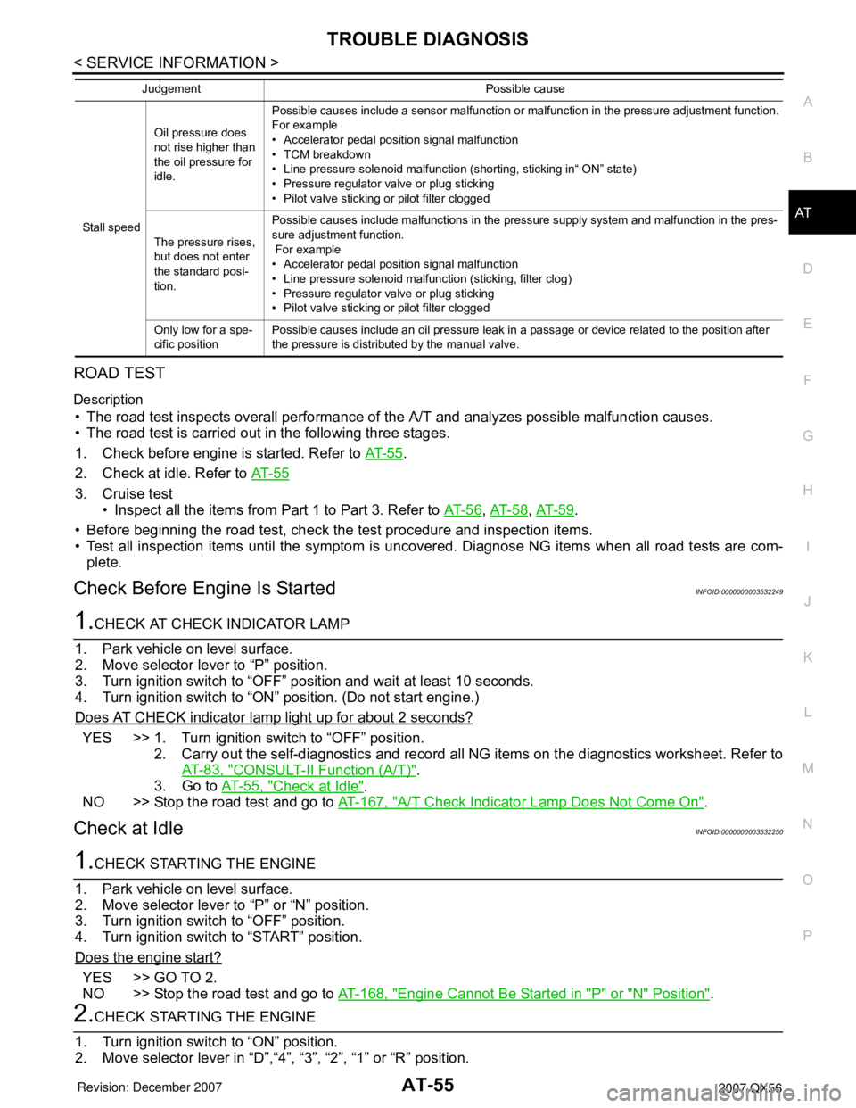
Stall speedOil pressure does
not rise higher than
the oil pressure for
idle.Possible causes include a sensor malfunction or malfunction in the pressure adjustment function.
For example
• Accelerator pedal position signal malfunction
• TCM breakdown
• Line pressure solenoid malfunction (shorting, sticking in“ ON” state)
• Pressure regulator valve or plug sticking
• Pilot valve sticking or pilot filter clogged
The pressure rises,
but does not enter
the standard posi-
tion.Possible causes include malfunctions in the pressure supply system and malfunction in the pres-
sure adjustment function.
For example
• Accelerator pedal position signal malfunction
• Line pressure solenoid malfunction (sticking, filter clog)
• Pressure regulator valve or plug sticking
• Pilot valve sticking or pilot filter clogged
Only low for a spe-
cific positionPossible causes include an oil pressure leak in a passage or device related to the position after
the pressure is distributed by the manual valve. Judgement Possible cause
Page 128 of 3061

AT-58
< SERVICE INFORMATION >
TROUBLE DIAGNOSIS
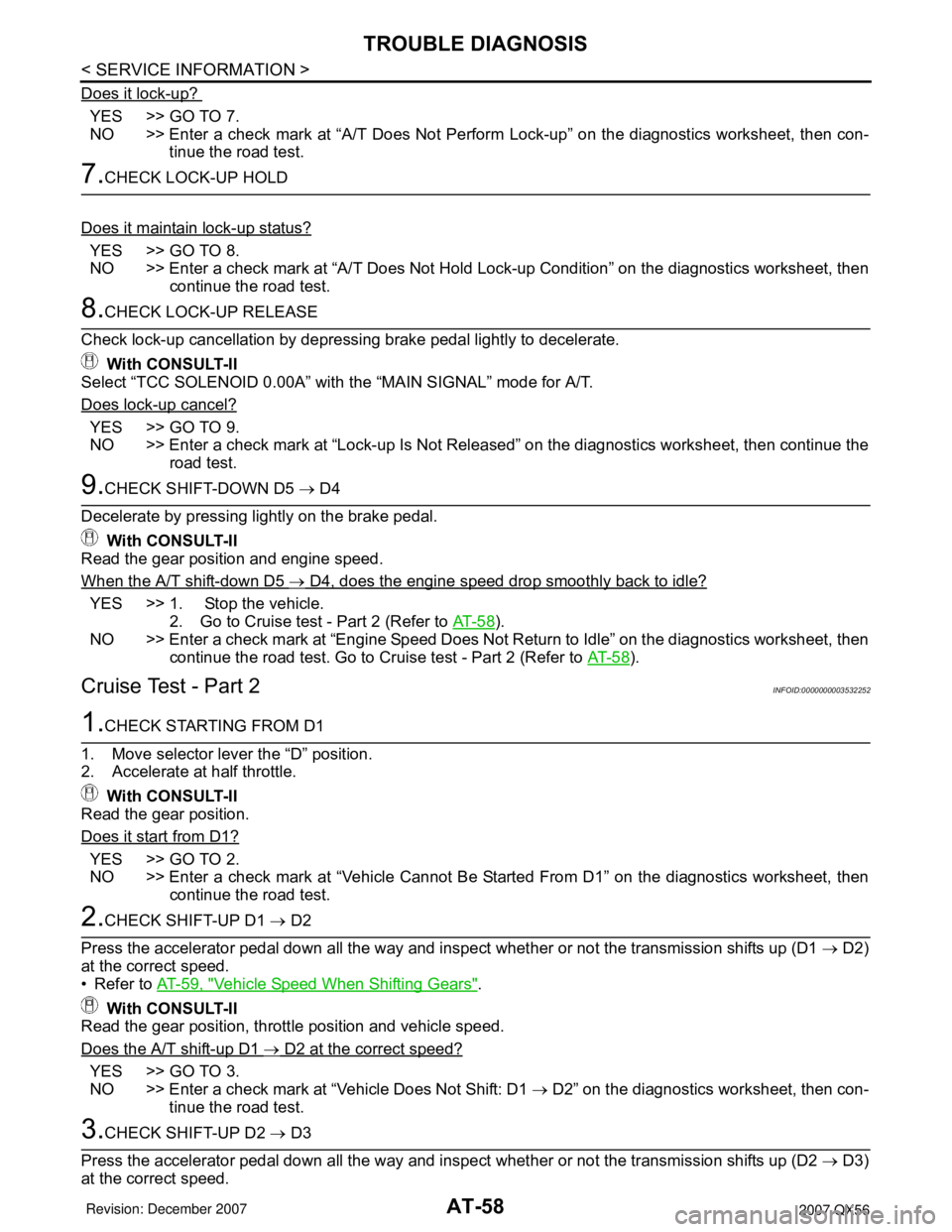
Does it lock-up?
YES >> GO TO 7.
NO >> Enter a check mark at “A/T Does Not Perform Lock-up” on the diagnostics worksheet, then con-
tinue the road test.
7.CHECK LOCK-UP HOLD
Does it maintain lock-up status?
YES >> GO TO 8.
NO >> Enter a check mark at “A/T Does Not Hold Lock-up Condition” on the diagnostics worksheet, then
continue the road test.
8.CHECK LOCK-UP RELEASE
Check lock-up cancellation by depressing brake pedal lightly to decelerate.
With CONSULT-II
Select “TCC SOLENOID 0.00A” with the “MAIN SIGNAL” mode for A/T.
Does lock-up cancel?
YES >> GO TO 9.
NO >> Enter a check mark at “Lock-up Is Not Released” on the diagnostics worksheet, then continue the
road test.
9.CHECK SHIFT-DOWN D5 → D4
Decelerate by pressing lightly on the brake pedal.
With CONSULT-II
Read the gear position and engine speed.
When the A/T shift-down D5
→ D4, does the engine speed drop smoothly back to idle?
YES >> 1. Stop the vehicle.
2. Go to Cruise test - Part 2 (Refer to AT- 5 8
).
NO >> Enter a check mark at “Engine Speed Does Not Return to Idle” on the diagnostics worksheet, then
continue the road test. Go to Cruise test - Part 2 (Refer to AT- 5 8
).
Cruise Test - Part 2INFOID:0000000003532252
1.CHECK STARTING FROM D1
1. Move selector lever the “D” position.
2. Accelerate at half throttle.
With CONSULT-II
Read the gear position.
Does it start from D1?
YES >> GO TO 2.
NO >> Enter a check mark at “Vehicle Cannot Be Started From D1” on the diagnostics worksheet, then
continue the road test.
2.CHECK SHIFT-UP D1 → D2
Press the accelerator pedal down all the way and inspect whether or not the transmission shifts up (D1 → D2)
at the correct speed.
• Refer to AT-59, "
Vehicle Speed When Shifting Gears".
With CONSULT-II
Read the gear position, throttle position and vehicle speed.
Does the A/T shift-up D1
→ D2 at the correct speed?
YES >> GO TO 3.
NO >> Enter a check mark at “Vehicle Does Not Shift: D1 → D2” on the diagnostics worksheet, then con-
tinue the road test.
3.CHECK SHIFT-UP D2 → D3
Press the accelerator pedal down all the way and inspect whether or not the transmission shifts up (D2 → D3)
at the correct speed.
Page 153 of 3061

TROUBLE DIAGNOSIS
AT-83
< SERVICE INFORMATION >
D
E
F
G
H
I
J
K
L
MA
B
AT
N
O
PCONSULT-II Function (A/T)INFOID:0000000003532259
CONSULT-II can display each diagnostic item using the diagnostic test modes shown following.
CONSULT-II REFERENCE VALUE
NOTICE:
1. The CONSULT-II electrically displays shift timing and lock-up timing (that is, operation timing of each sole-
noid).
Check for time difference between actual shift timing and the CONSULT-II display. If the difference is
noticeable, mechanical parts (except solenoids, sensors, etc.) may be malfunctioning. Check mechanical
parts using applicable diagnostic procedures.
2. Shift schedule (which implies gear position) displayed on CONSULT-II and that indicated in Service Man-
ual may differ slightly. This occurs because of the following reasons:
- Actual shift schedule has more or less tolerance or allowance,
- Shift schedule indicated in Service Manual refers to the point where shifts start, and
- Gear position displayed on CONSULT-II indicates the point where shifts are completed.
3. Display of solenoid valves on CONSULT-II changes at the start of shifting, while gear position is displayed
upon completion of shifting (which is computed by TCM).
9 B/R Starter relaySelector lever in “N”,“ P” positions. Battery voltage
Selector lever in other positions. 0V
10 B Ground Always 0V Te r m i n a l
No.Wire
colorItem Condition Data (Pyrex.)
TCM diagnostic mode Description
WORK SUPPORTSupports inspections and adjustments. Commands are transmitted to the TCM for setting the status
suitable for required operation, input/output signals are received from the TCM and received data is
displayed.
SELF-DIAG RESULTS Displays TCM self-diagnosis results.
DATA MONITOR Displays TCM input/output data in real time.
CAN DIAG SUPPORT MNTR The result of transmit/receive diagnosis of CAN communication can be read.
ACTIVE TEST Operation of electrical loads can be checked by sending drive signal to them.
FUNCTION TEST Conducted by CONSULT-II instead of a technician to determine whether each system is “OK” or “NG”.
ECU PART NUMBER TCM part number can be read.
Item name Condition Display value (Approx.)
ATF TEMP SE 1
0°C (32° F) - 20°C (68°F) - 80°C (176°F)3.3 - 2.7 - 0.9 V
ATF TEMP SE 23.3 - 2.5 - 0.7 V
TCC SOLENOIDWhen perform slip lock-up 0.2 - 0.4 A
When perform lock-up 0.4 - 0.6 A
SLCT LVR POSISelector lever in “N”,“P” position. N/P
Selector lever in “R” position. R
Selector lever in “D” position. D
Selector lever in “4” position. 4
Selector lever in “3” position. 3
Selector lever in “2” position. 2
Selector lever in “1” position. 1
VHCL/S SE·A/T During drivingApproximately matches the
speedometer reading.
ENGINE SPEED Engine runningClosely matches the tachometer
reading.