ad blue INFINITI QX56 2007 Factory User Guide
[x] Cancel search | Manufacturer: INFINITI, Model Year: 2007, Model line: QX56, Model: INFINITI QX56 2007Pages: 3061, PDF Size: 64.56 MB
Page 629 of 3061

NAVIGATION SYSTEM
AV-89
< SERVICE INFORMATION >
C
D
E
F
G
H
I
J
L
MA
B
AV
N
O
P
Terminal and Reference Value for NAVI Control UnitINFOID:0000000003533713
Te r m i n a l N o .
(Wire color)
ItemSignal
input/
outputCondition
Vo l ta g e
(Approx.)Example of
symptom
+–Igni-
tion
switchOperation
1 (B) Ground Ground – ON – 0V –
2 (Y) Ground Battery power Input OFF – Battery voltageSystem does not
work properly.
5 (O) Ground ACC signal Input ACC – Battery voltageSystem does not
work properly.
12 (B) 14 (W)Voice guide
signalOutput ONPress the “GUIDE/
VOICE” button.Only route guide
and operation
guide are not
heard.
13 – Shield ground – – – –Audio noise in-
terference.
44 (R) 47RGB signal
(R: red)Output ONSelect “Display Di-
agnosis (NAVI)” of
CONFIRMATION/
ADJUSTMENT
function.NAVI screen
looks bluish.
45 (R/W) 47RGB signal
(G: green)Output ONSelect “Display Di-
agnosis (NAVI)” of
CONFIRMATION/
ADJUSTMENT
function.NAVI screen
looks reddish.
46 (B) 47RGB signal
(B: blue)Output ONSelect “Display Di-
agnosis (NAVI)” of
CONFIRMATION/
ADJUSTMENT
function.NAVI screen
looks yellowish.
47 – Shield ground – – – –Video display in-
terference.
48 (BR) 49RGB syn-
chronizing
signalOutput ONPress the “MAP”
button.NAVI screen is
rolling.
SKIA0171J
SKIA4977E
SKIA4978E
SKIA4979E
SKIA0164E
Page 633 of 3061

NAVIGATION SYSTEM
AV-93
< SERVICE INFORMATION >
C
D
E
F
G
H
I
J
L
MA
B
AV
N
O
P
42 (W/L) GroundAudio RX
communica-
tion signalInput ONOperate audio
volume.Audio does not
operate properly.
43 (W) 41RGB syn-
chronizing
signalInput ONPress the “MAP”
button.NAVI screen is
rolling.
44 (R/L) 45RGB signal
(R: red)Input ONSelect “Display Di-
agnosis (NAVI)” of
CONFIRMATION/
ADJUSTMENT
function.NAVI screen
looks bluish.
45 – Shield ground – – – – –
46 (R/W) 45RGB signal
(G: green)Input ONSelect “Display Di-
agnosis (NAVI)” of
CONFIRMATION/
ADJUSTMENT
function.NAVI screen
looks reddish.
47 – Shield ground – – – – –
48 (B) 45RGB signal
(B: blue)Input ONSelect “Display Di-
agnosis (NAVI)” of
CONFIRMATION/
ADJUSTMENT
function.NAVI screen
looks yellowish.
49 – Shield ground – – – – –
50 (R/L) 47RGB signal
(R: red)Output ONSelect “Display Di-
agnosis (DCU)” of
CONFIRMATION/
ADJUSTMENT
function.NAVI screen
looks bluish. Te r m i n a l N o .
(Wire color)
ItemSignal
input/
outputCondition
Vo l ta g e
(Approx.)Example of
symptom
+–Igni-
tion
switchOperation
SKIA4403E
SKIA0164E
SKIA4977E
SKIA4978E
SKIA4979E
SKIA4980E
Page 634 of 3061

AV-94
< SERVICE INFORMATION >
NAVIGATION SYSTEM
51 (B) 49RGB area
(YS) signalOutput ONPress the“TRIP”
button.RGB screen is
not shown.
52 (R/W) 47RGB signal
(G: green)Output ONSelect “Display Di-
agnosis (DCU)” of
CONFIRMATION/
ADJUSTMENT
function.Screen looks
reddish.
53 (W) 49Vertical syn-
chronizing
(VP) signalInput ON –Operating
screen for audio
and A/C is not
displayed when
showing NAVI
screen.
54 (B) 47RGB signal
(B: blue)Output ONSelect “Display Di-
agnosis (DCU)” of
CONFIRMATION/
ADJUSTMENT
function.Screen looks
yellowish.
55 (R) 49Horizontal
synchroniz-
ing (HP) sig-
nalInput ON –Operating
screen for audio
and A/C is not
displayed when
showing NAVI
screen.
56 (G) 49RGB syn-
chronizing
signalOutput ONPress the “TRIP”
button.NAVI screen is
rolling. Te r m i n a l N o .
(Wire color)
ItemSignal
input/
outputCondition
Voltag e
(Approx.)Example of
symptom
+–Igni-
tion
switchOperation
SKIA0162E
SKIA4981E
SKIA4983E
SKIA4982E
SKIA4983E
SKIA0164E
Page 636 of 3061

AV-96
< SERVICE INFORMATION >
NAVIGATION SYSTEM
Terminal and Reference Value for AV Switch
INFOID:0000000003533716
18 (B) 7RGB signal
(B: blue)Input ONSelect “Display Di-
agnosis (DCU)” of
CONFIRMATION/
ADJUSTMENT
function.Screen looks
yellowish.
19 (G) 21RGB syn-
chronizing
signalInput ONPress the “TRIP”
button.NAVI screen is
rolling.
20 (W) 21Vertical syn-
chronizing
(VP) signalOutput ON –Operating
screen for audio
and A/C is not
displayed when
showing NAVI
screen.
21 – Shield ground – – – – –
22 (L) 23Display com-
munication
signal
(DSP-DCU)Output ON –Though a screen
is displayed, it is
impossible to ad-
just brightness.
23 – Shield ground – – – – – Terminal No. (Wire
color)
ItemSignal
input/
outputCondition
Voltag e
(Approx.)Example of
symptom
+–Igni-
tion
switchOperation
SKIA4982E
SKIA0164E
SKIA4983E
SKIA4363E
Te r m i n a l N o .
(Wire color)
ItemSignal
input/
outputCondition
Vo l ta g e
(Approx.)Example of
symptom
+–Ignition
switchOperation
1 (Y) Ground Battery power Input OFF - Battery voltageSystem does not
work properly.
2 (V) Ground ACC signal Input ACC - Battery voltageSystem does not
work properly.
3 (R/L) GroundIllumination
signalInput OFFLighting switch is
ON (position 1).Battery voltageAV switch illumi-
nation does not
come on when
lighting switch is
ON (position 1). Turn lighting switch
OFF.3.0V or less
Page 644 of 3061

AV-104
< SERVICE INFORMATION >
NAVIGATION SYSTEM
5. When “Confirmation/Adjustment” is selected on the initial self-
diagnosis screen, the operation will enter the CONFIRMATION/
ADJUSTMENT mode. In this mode, check and adjustment of
each item will become possible.
6. The initial trouble diagnosis screen will be shown, and items
“Display Diagnosis”, “Vehicle Signals”, “Auto Climate Control”
and “Navigation” will become selective.
7. Select each switch on “CONFIRMATION/ADJUSTMENT”
screen to display the relevant diagnosis screen.
DISPLAY DIAGNOSIS
• When RGB signal error occurred in the RGB system, tone of the color bar will change as follows.
• When the color of the screen looks unusual, refer to AV-125, "
Color of RGB Image Is Not Proper (Only NAVI
Screen Looks Bluish)", AV-129, "Color of RGB Image Is Not Proper (All Screens Look Reddish)" and AV-
129, "Color of RGB Image Is Not Proper (All Screens Look Yellowish)".
VEHICLE SIGNALS
• A comparison check can be made of each actual vehicle signal
and the signals recognized by the system.
CAUTION:
In case of confirming light signal, set D/N mode to ON/OFF of
lighting switch (normal setting).
• OFF: D (Day mode)
• ON: N (Night mode)
Unless above setting, light signal (ON/OFF) may not be accu-
rately displayed.
SKIA4220E
WKIA4316E
R (red) signal error : Screen looks bluish
G (green) signal error : Screen looks reddish
B (blue) signal error : Screen looks yellowish
WKIA4306E
Diagnosis item Display Condition Remarks
Vehicle speedON Vehicle speed > 0 km/h (0 MPH)
Changes in indication may be delayed by ap-
prox. 1.5 seconds. This is normal. OFF Vehicle speed = 0 km/h (0 MPH)
– Ignition switch in ACC position
Page 645 of 3061

NAVIGATION SYSTEM
AV-105
< SERVICE INFORMATION >
C
D
E
F
G
H
I
J
L
MA
B
AV
N
O
P
• If vehicle speed is NG, refer to AV-115, "Vehicle Speed Signal Inspection for Display Control Unit".
• If light is NG, refer to AV-116, "
Illumination Signal Inspection for Display Control Unit".
• If IGN is NG, refer to AV-117, "
Ignition Signal Inspection for Display Control Unit".
• If reverse is NG, refer to AV-118, "
Reverse Signal Inspection for Display Control Unit".
NAVIGATION
1. The initial confirmation/adjustment screen will be shown, and
items “Display Diagnosis”, “Vehicle Signals”, “Navigation”,
"Error History“ and "Delete Unit Connection Log” will become
selective.
2. Select each switch on “CONFIRMATION/ADJUSTMENT”
screen to display the relevant diagnosis screen.
DISPLAY DIAGNOSIS
• When RGB signal error occurred in the RGB system, tone of the color bar will change as follows.
• When the color of the screen looks unusual, refer to AV-125, "
Color of RGB Image Is Not Proper (Only NAVI
Screen Looks Bluish)", AV-126, "Color of RGB Image Is Not Proper (Only NAVI Screen Looks Reddish)" and
AV-127, "
Color of RGB Image Is Not Proper (Only NAVI Screen Looks Yellowish)".
VEHICLE SIGNALS
LightON Lighting switch ON
–
OFF Lighting switch OFF
IGNON Ignition switch ON
–
OFF Ignition switch ACC
ReverseON Selector lever in R position
Changes in indication may be delayed by ap-
prox. 1.5 seconds. This is normal. OFF Selector lever in other than R position
– Ignition switch in ACC position Diagnosis item Display Condition Remarks
WKIA4311E
WKIA4317E
R (red) signal error : Screen looks bluish
G (green) signal error : Screen looks reddish
B (blue) signal error : Screen looks yellowish
Page 1802 of 3061

EM-32
< SERVICE INFORMATION >
FUEL INJECTOR AND FUEL TUBE
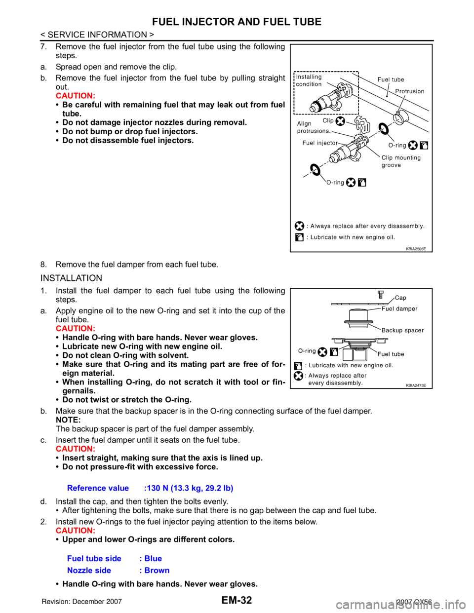
7. Remove the fuel injector from the fuel tube using the followingsteps.
a. Spread open and remove the clip.
b. Remove the fuel injector from the fuel tube by pulling straight out.
CAUTION:
• Be careful with remaining fuel that may leak out from fueltube.
• Do not damage injector nozzles during removal.
• Do not bump or drop fuel injectors.
• Do not disassemble fuel injectors.
8. Remove the fuel damper from each fuel tube.
INSTALLATION
1. Install the fuel damper to each fuel tube using the following steps.
a. Apply engine oil to the new O-ring and set it into the cup of the fuel tube.
CAUTION:
• Handle O-ring with bare hands. Never wear gloves.
• Lubricate new O-ring with new engine oil.
• Do not clean O-ring with solvent.
• Make sure that O-ring and its mating part are free of for-eign material.
• When installing O-ring, do not scratch it with tool or fin-
gernails.
• Do not twist or stretch the O-ring.
b. Make sure that the backup spacer is in the O-ring connecting surface of the fuel damper.
NOTE:
The backup spacer is part of the fuel damper assembly.
c. Insert the fuel damper until it seats on the fuel tube. CAUTION:
• Insert straight, making sure that the axis is lined up.
• Do not pressure-fit with excessive force.
d. Install the cap, and then tighten the bolts evenly. • After tightening the bolts, make sure that there is no gap between the cap and fuel tube.
2. Install new O-rings to the fuel injector paying attention to the items below. CAUTION:
• Upper and lower O-rings are different colors.
• Handle O-ring with bare hands. Never wear gloves.
KBIA2506E
Reference value :130 N (13.3 kg, 29.2 lb)
Fuel tube side : Blue
Nozzle side : Brown
KBIA2473E
Page 1842 of 3061

EM-72
< SERVICE INFORMATION >
CYLINDER HEAD
VALVE SEAT CONTACT
• After confirming that the dimensions of the valve guides and valves
are within specifications, perform this procedure.
• Apply prussian blue (or white lead) onto the contacting surface of
the valve seat to check the condition of the valve contact on the
surface.
• Check if the contact area band is continuous all around the circum-
ference.
• If not, grind to adjust the valve fit and check again. If the contacting
surface still has NG conditions even after the re-check, replace the
valve seat.
VALVE SEAT REPLACEMENT
When the valve seat is removed, replace it with oversized (0.5 mm, 0.020 in) valve seat.
1. Bore out the old seat until it collapses. Boring should not continue beyond the bottom face of the seat
recess in the cylinder head. Set the machine depth stop to ensure this.
2. Ream the cylinder head recess diameter for service valve seat.
• Be sure to ream in circles concentric to the valve guide center.
• This will enable valve seat to fit correctly.
3. Heat the cylinder head to 110° to 130°C (230° to 266°F) by
soaking it in heated oil.
4. Cool the valve seats well with dry ice. Force fit the valve seat into the cylinder head.
CAUTION:
• Avoid directly touching cold valve seats.
• Cylinder head contains heat. When working, wear protective equipment to avoid getting burned.
5. Finish the seat to the specified dimensions using suitable tool.
Refer to EM-103, "
Standard and Limit".
CAUTION:
When using valve seat cutter, firmly grip the cutter handle
with both hands. Then, press on the contacting surface all
around the circumference to cut in a single drive. Improper
pressure on the cutter or cutting many different times may
result in stage valve seat.
SBIA0322E
Oversize [0.5 mm (0.020 in)] (Service):
Intake : 38.500 - 38.516 mm (1.5157 - 1.5164 in)
Exhaust : 32.700 - 32.716 mm (1.2874 - 1.2880 in)
SEM795A
SEM008A
SEM934C
Page 1862 of 3061

EM-92
< SERVICE INFORMATION >
CYLINDER BLOCK
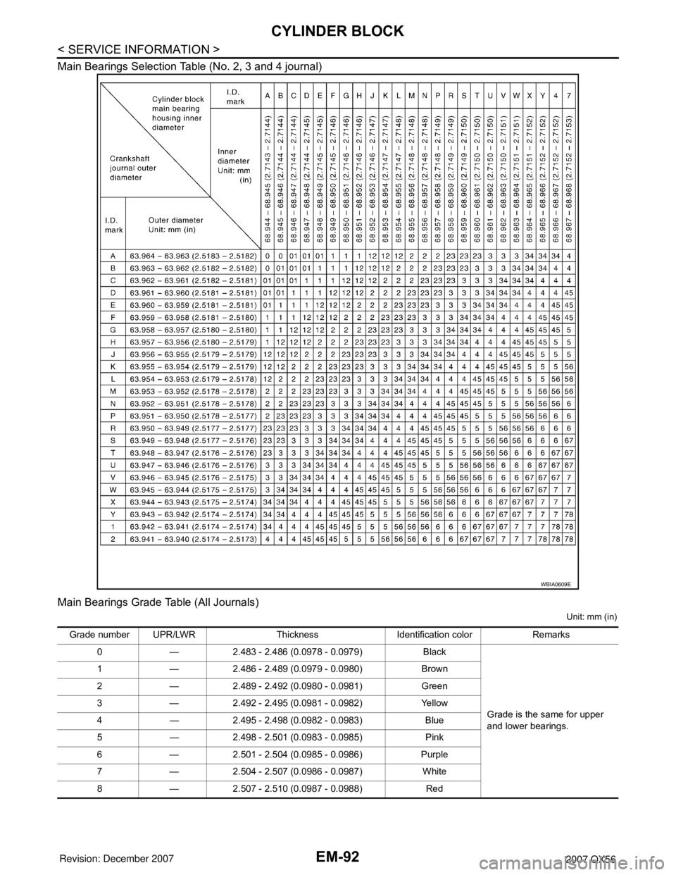
Main Bearings Selection Table (No. 2, 3 and 4 journal)
Main Bearings Grade Table (All Journals)
Unit: mm (in)
WBIA0609E
Grade number UPR/LWR Thickness Identification color Remarks
0 — 2.483 - 2.486 (0.0978 - 0.0979) Black
Grade is the same for upper
and lower bearings. 1 — 2.486 - 2.489 (0.0979 - 0.0980) Brown
2 — 2.489 - 2.492 (0.0980 - 0.0981) Green
3 — 2.492 - 2.495 (0.0981 - 0.0982) Yellow
4 — 2.495 - 2.498 (0.0982 - 0.0983) Blue
5 — 2.498 - 2.501 (0.0983 - 0.0985) Pink
6 — 2.501 - 2.504 (0.0985 - 0.0986) Purple
7 — 2.504 - 2.507 (0.0986 - 0.0987) White
8 — 2.507 - 2.510 (0.0987 - 0.0988) Red
Page 1863 of 3061

CYLINDER BLOCK
EM-93
< SERVICE INFORMATION >
C
D
E
F
G
H
I
J
K
L
MA
EM
N
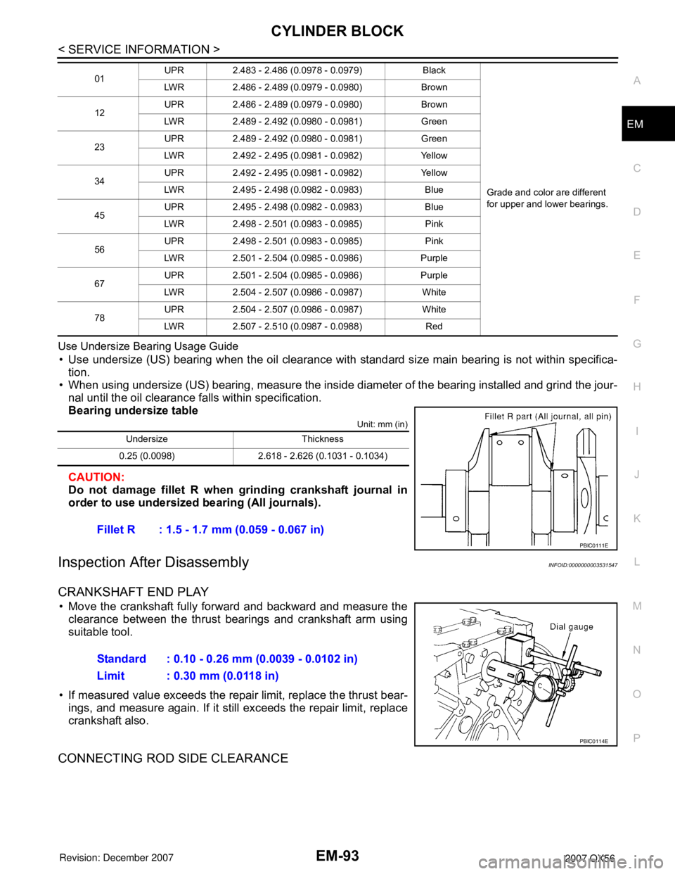
P O Use Undersize Bearing Usage Guide
• Use undersize (US) bearing when the oil clearance with standard size main bearing is not within specifica-
tion.
• When using undersize (US) bearing, measure the inside diameter of the bearing installed and grind the jour-
nal until the oil clearance falls within specification.
Bearing undersize table
Unit: mm (in)
CAUTION:
Do not damage fillet R when grinding crankshaft journal in
order to use undersized bearing (All journals).
Inspection After DisassemblyINFOID:0000000003531547
CRANKSHAFT END PLAY
• Move the crankshaft fully forward and backward and measure the
clearance between the thrust bearings and crankshaft arm using
suitable tool.
• If measured value exceeds the repair limit, replace the thrust bear-
ings, and measure again. If it still exceeds the repair limit, replace
crankshaft also.
CONNECTING ROD SIDE CLEARANCE
01UPR 2.483 - 2.486 (0.0978 - 0.0979) Black
Grade and color are different
for upper and lower bearings. LWR 2.486 - 2.489 (0.0979 - 0.0980) Brown
12UPR 2.486 - 2.489 (0.0979 - 0.0980) Brown
LWR 2.489 - 2.492 (0.0980 - 0.0981) Green
23UPR 2.489 - 2.492 (0.0980 - 0.0981) Green
LWR 2.492 - 2.495 (0.0981 - 0.0982) Yellow
34UPR 2.492 - 2.495 (0.0981 - 0.0982) Yellow
LWR 2.495 - 2.498 (0.0982 - 0.0983) Blue
45UPR 2.495 - 2.498 (0.0982 - 0.0983) Blue
LWR 2.498 - 2.501 (0.0983 - 0.0985) Pink
56UPR 2.498 - 2.501 (0.0983 - 0.0985) Pink
LWR 2.501 - 2.504 (0.0985 - 0.0986) Purple
67UPR 2.501 - 2.504 (0.0985 - 0.0986) Purple
LWR 2.504 - 2.507 (0.0986 - 0.0987) White
78UPR 2.504 - 2.507 (0.0986 - 0.0987) White
LWR 2.507 - 2.510 (0.0987 - 0.0988) Red
Undersize Thickness
0.25 (0.0098) 2.618 - 2.626 (0.1031 - 0.1034)
Fillet R : 1.5 - 1.7 mm (0.059 - 0.067 in)
PBIC0111E
Standard : 0.10 - 0.26 mm (0.0039 - 0.0102 in)
Limit : 0.30 mm (0.0118 in)
PBIC0114E