ad blue INFINITI QX56 2007 Factory Owner's Manual
[x] Cancel search | Manufacturer: INFINITI, Model Year: 2007, Model line: QX56, Model: INFINITI QX56 2007Pages: 3061, PDF Size: 64.56 MB
Page 1881 of 3061
SERVICE DATA AND SPECIFICATIONS (SDS)
EM-111
< SERVICE INFORMATION >
C
D
E
F
G
H
I
J
K
L
MA
EM
N
P O
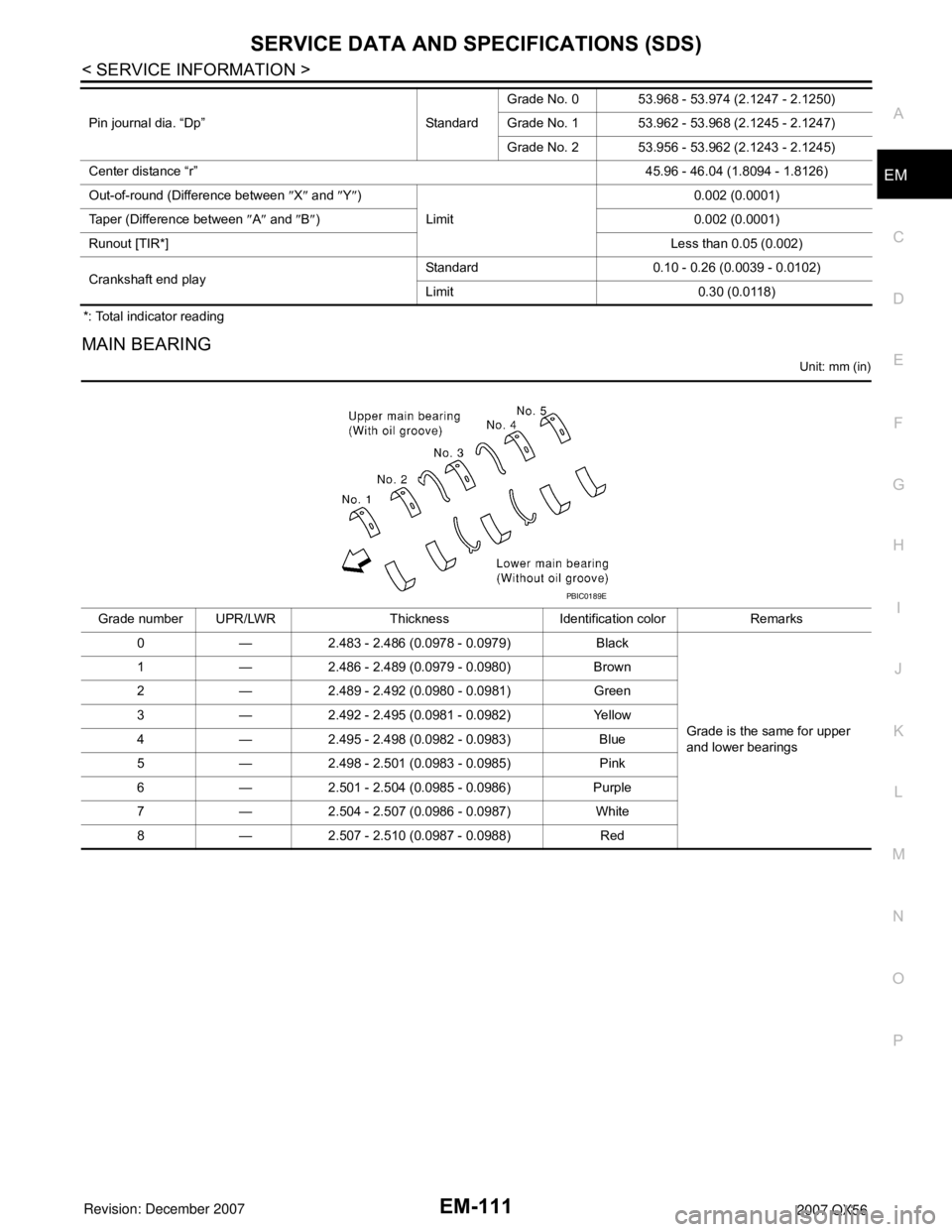
*: Total indicator reading
MAIN BEARING
Unit: mm (in)
Pin journal dia. “Dp” StandardGrade No. 0 53.968 - 53.974 (2.1247 - 2.1250)
Grade No. 1 53.962 - 53.968 (2.1245 - 2.1247)
Grade No. 2 53.956 - 53.962 (2.1243 - 2.1245)
Center distance “r”45.96 - 46.04 (1.8094 - 1.8126)
Out-of-round (Difference between ″X″ and ″Y″)
Limit0.002 (0.0001)
Taper (Difference between ″A″ and ″B″) 0.002 (0.0001)
Runout [TIR*]Less than 0.05 (0.002)
Crankshaft end playStandard 0.10 - 0.26 (0.0039 - 0.0102)
Limit 0.30 (0.0118)
Grade number UPR/LWR Thickness Identification color Remarks
0 — 2.483 - 2.486 (0.0978 - 0.0979) Black
Grade is the same for upper
and lower bearings 1 — 2.486 - 2.489 (0.0979 - 0.0980) Brown
2 — 2.489 - 2.492 (0.0980 - 0.0981) Green
3 — 2.492 - 2.495 (0.0981 - 0.0982) Yellow
4 — 2.495 - 2.498 (0.0982 - 0.0983) Blue
5 — 2.498 - 2.501 (0.0983 - 0.0985) Pink
6 — 2.501 - 2.504 (0.0985 - 0.0986) Purple
7 — 2.504 - 2.507 (0.0986 - 0.0987) White
8 — 2.507 - 2.510 (0.0987 - 0.0988) Red
PBIC0189E
Page 1882 of 3061

EM-112
< SERVICE INFORMATION >
SERVICE DATA AND SPECIFICATIONS (SDS)
Undersize
Unit: mm (in)
Main Bearing Oil Clearance
Unit: mm (in)
Connecting Rod Bearing
Undersize
Unit: mm (in)
Connecting Rod Bearing Oil Clearance
Unit: mm (in)
01UPR 2.483 - 2.486 (0.0978 - 0.0979) Black
Grade is different for upper and
lower bearings. LWR 2.486 - 2.489 (0.0979 - 0.0980) Brown
12UPR 2.486 - 2.489 (0.0979 - 0.0980) Brown
LWR 2.489 - 2.492 (0.0980 - 0.0981) Green
23UPR 2.489 - 2.492 (0.0980 - 0.0981) Green
LWR 2.492 - 2.495 (0.0981 - 0.0982) Yellow
34UPR 2.492 - 2.495 (0.0981 - 0.0982) Yellow
LWR 2.495 - 2.498 (0.0982 - 0.0983) Blue
45UPR 2.495 - 2.498 (0.0982 - 0.0983) Blue
LWR 2.498 - 2.501 (0.0983 - 0.0985) Pink
56UPR 2.498 - 2.501 (0.0983 - 0.0985) Pink
LWR 2.501 - 2.504 (0.0985 - 0.0986) Purple
67UPR 2.501 - 2.504 (0.0985 - 0.0986) Purple
LWR 2.504 - 2.507 (0.0986 - 0.0987) White
78UPR 2.504 - 2.507 (0.0986 - 0.0987) White
LWR 2.507 - 2.510 (0.0987 - 0.0988) Red
Undersize Thickness Main journal diameter
0.25 (0.0098) 2.618 - 2.626 (0.1031 - 0.1034) Grind so that bearing clearance is the specified value.
Items Standard Limit
Main bearing oil clearanceNo.1 and 5 0.001 - 0.011 (0.00004 - 0.0004) 0.021 (0.0008)
No.2, 3 and 4 0.007 - 0.017 (0.0003 - 0.0007) 0.027 (0.0011)
Grade number Thickness “T” mm (in) Identification color (mark)
0 1.500 - 1.503 (0.0591 - 0.0592) Black
1 1.503 - 1.506 (0.0592 - 0.0593) Brown
2 1.506 - 1.509 (0.0593 - 0.0594) Green
3 1.509 - 1.512 (0.0594 - 0.0595) Yellow
Undersize Thickness Crank pin journal diameter “Dp”
0.25 (0.0098) 1.627 - 1.635 (0.0641 - 0.0644) Grind so that bearing clearance is the specified value.
Items Standard Limit
Connecting rod bearing oil clearance 0.020 - 0.039 (0.0008 - 0.0015) 0.055 (0.0022)
Page 1983 of 3061

HOW TO USE THIS MANUAL
GI-17
< SERVICE INFORMATION >
C
D
E
F
G
H
I
J
K
L
MB
GI
N
O
P
Harness Indication
14 Wire color• This shows a code for the color of the wire.
B = Black
W = White
R = Red
G = Green
L = Blue
Y = Yellow
LG = Light GreenBR = Brown
OR or O = Orange
P = Pink
PU or V (Violet) = Purple
GY or GR = Gray
SB = Sky Blue
CH = Dark Brown
DG = Dark Green
When the wire color is striped, the base color is given first, followed by the stripe color as shown
below:
Example: L/W = Blue with White Stripe
15 Option description • This shows a description of the option abbreviation used on the page.
16 Switch• This shows that continuity exists between terminals 1 and 2 when the switch is in the A posi-
tion. Continuity exists between terminals 1 and 3 when the switch is in the B position.
17 Assembly parts • Connector terminal in component shows that it is a harness incorporated assembly.
18 Cell code• This identifies each page of the wiring diagram by section, system and wiring diagram page
number.
19 Current flow arrow• Arrow indicates electric current flow, especially where the direction of standard flow (vertically
downward or horizontally from left to right) is difficult to follow.
• A double arrow “ ” shows that current can flow in either direction depending on circuit
operation.
20 System branch• This shows that the system branches to another system identified by cell code (section and
system).
21 Page crossing• This arrow shows that the circuit continues to another page identified by cell code.
• The C will match with the C on another page within the system other than the next or preceding
pages.
22 Shielded line • The line enclosed by broken line circle shows shield wire.
23Component box in
wave line• This shows that another part of the component is also shown on another page (indicated by
wave line) within the system.
24 Component name • This shows the name of a component.
25 Connector number• This shows the connector number.
• The letter shows which harness the connector is located in.
•Example: M: main harness. For detail and to locate the connector, refer to PG section "Main
Harness", “Harness Layout”. A coordinate grid is included for complex harnesses to aid in lo-
cating connectors.
26 Ground (GND)• The line spliced and grounded under wire color shows that ground line is spliced at the ground-
ed connector.
27 Ground (GND)• This shows the ground connection. For detailed ground distribution information, refer to
"Ground Distribution" in PG section.
28 Connector views • This area shows the connector faces of the components in the wiring diagram on the page.
29 Common component• Connectors enclosed in broken line show that these connectors belong to the same compo-
nent.
30 Connector color• This shows a code for the color of the connector. For code meaning, refer to wire color codes,
Number 14 of this chart.
31Fusible link and fuse
box• This shows the arrangement of fusible link(s) and fuse(s), used for connector views of "POW-
ER SUPPLY ROUTING" in PG section.
The open square shows current flow in, and the shaded square shows current flow out.
32 Reference area• This shows that more information on the Super Multiple Junction (SMJ) and Joint Connectors
(J/C) exists on the PG section. Refer to "Reference Area" for details. Num-
berItem Description
Page 2011 of 3061
RECOMMENDED CHEMICAL PRODUCTS AND SEALANTS
GI-45
< SERVICE INFORMATION >
C
D
E
F
G
H
I
J
K
L
MB
GI
N
O
PRECOMMENDED CHEMICAL PRODUCTS AND SEALANTS
Recommended Chemical Product and SealantINFOID:0000000003531502
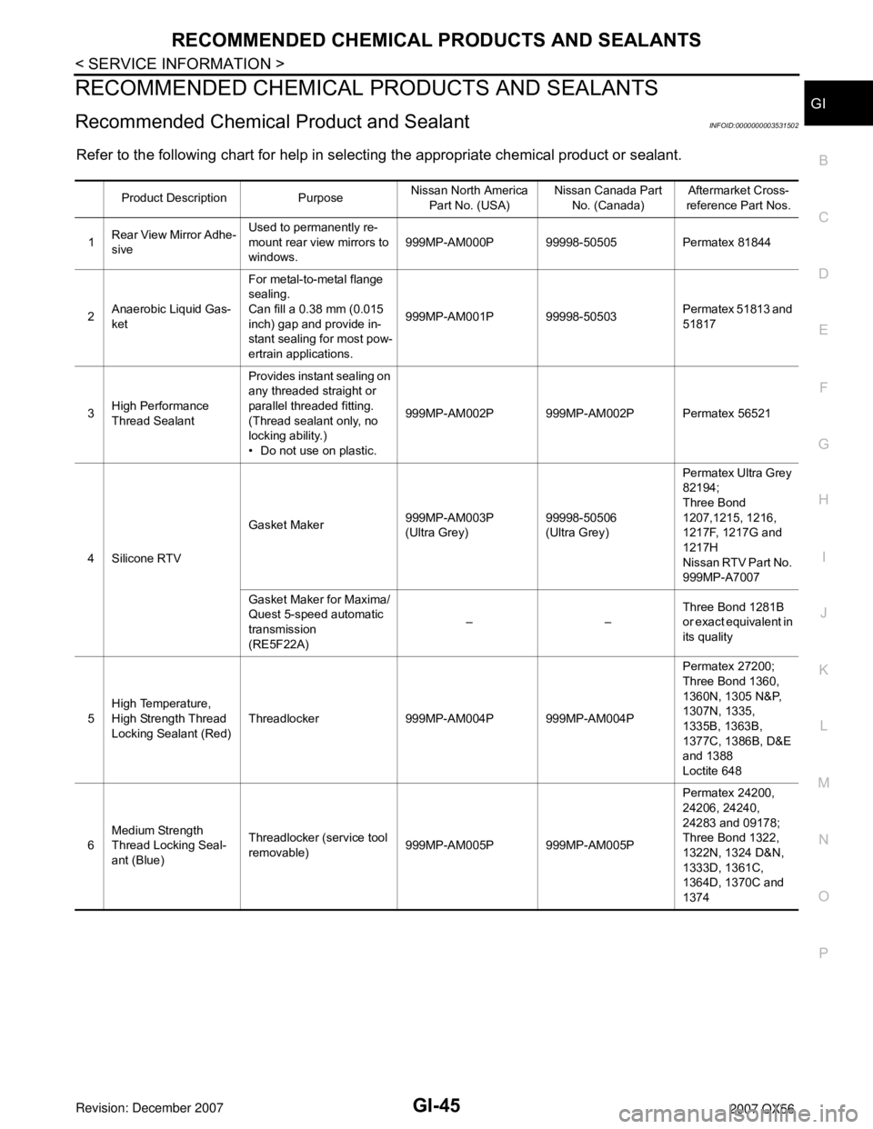
Refer to the following chart for help in selecting the appropriate chemical product or sealant.
Product Description PurposeNissan North America
Part No. (USA)Nissan Canada Part
No. (Canada)Aftermarket Cross-
reference Part Nos.
1Rear View Mirror Adhe-
siveUsed to permanently re-
mount rear view mirrors to
windows.999MP-AM000P 99998-50505 Permatex 81844
2Anaerobic Liquid Gas-
ketFor metal-to-metal flange
sealing.
Can fill a 0.38 mm (0.015
inch) gap and provide in-
stant sealing for most pow-
ertrain applications.999MP-AM001P 99998-50503Permatex 51813 and
51817
3High Performance
Thread SealantProvides instant sealing on
any threaded straight or
parallel threaded fitting.
(Thread sealant only, no
locking ability.)
• Do not use on plastic.999MP-AM002P 999MP-AM002P Permatex 56521
4 Silicone RTVGasket Maker999MP-AM003P
(Ultra Grey)99998-50506
(Ultra Grey)Permatex Ultra Grey
82194;
Three Bond
1207,1215, 1216,
1217F, 1217G and
1217H
Nissan RTV Part No.
999MP-A7007
Gasket Maker for Maxima/
Quest 5-speed automatic
transmission
(RE5F22A)––Three Bond 1281B
or exact equivalent in
its quality
5High Temperature,
High Strength Thread
Locking Sealant (Red)Threadlocker 999MP-AM004P 999MP-AM004PPermatex 27200;
Three Bond 1360,
1360N, 1305 N&P,
1307N, 1335,
1335B, 1363B,
1377C, 1386B, D&E
and 1388
Loctite 648
6Medium Strength
Thread Locking Seal-
ant (Blue)Threadlocker (service tool
removable)999MP-AM005P 999MP-AM005PPermatex 24200,
24206, 24240,
24283 and 09178;
Three Bond 1322,
1322N, 1324 D&N,
1333D, 1361C,
1364D, 1370C and
1374
Page 2490 of 3061
SERVICE DATA AND SPECIFICATIONS (SDS)
PR-13
< SERVICE INFORMATION >
C
E
F
G
H
I
J
K
L
MA
B
PR
N
O
P
SERVICE DATA AND SPECIFICATIONS (SDS)
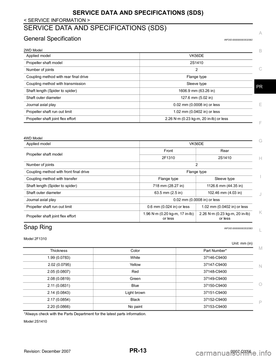
General SpecificationINFOID:0000000003532582
2WD Model
4WD Model
Snap RingINFOID:0000000003532583
Model 2F1310
Unit: mm (in)
*Always check with the Parts Department for the latest parts information.
Model 2S1410
Applied modelVK56DE
Propeller shaft model2S1410
Number of joints2
Coupling method with rear final drive Flange type
Coupling method with transmission Sleeve type
Shaft length (Spider to spider) 1606.9 mm (63.26 in)
Shaft outer diameter 127.6 mm (5.02 in)
Journal axial play 0.02 mm (0.0008 in) or less
Propeller shaft run out limit 1.02 mm (0.0402 in) or less
Propeller shaft joint flex effort 2.26 N·m (0.23 kg-m, 20 in-lb) or less
Applied modelVK56DE
Propeller shaft modelFront Rear
2F1310 2S1410
Number of joints2
Coupling method with front final drive Flange type
Coupling method with transfer Flange type Sleeve type
Shaft length (Spider to spider) 718 mm (28.27 in) 1126.6 mm (44.35 in)
Shaft outer diameter 63.5 mm (2.5 in) 102.46 mm (4.03 in)
Journal axial play 0.02 mm (0.0008 in) or less
Propeller shaft run out limit 0.6 mm (0.024 in) or less 1.02 mm (0.0402 in) or less
Propeller shaft joint flex effort1.96 N·m (0.20 kg-m, 17 in-lb)
or less2.26 N·m (0.23 kg-m, 20 in-lb)
or less
Thickness Color Part Number*
1.99 (0.0783) White 37146-C9400
2.02 (0.0795) Yellow 37147-C9400
2.05 (0.0807) Red 37148-C9400
2.08 (0.0819) Green 37149-C9400
2.11 (0.0831) Blue 37150-C9400
2.14 (0.0843) Light brown 37151-C9400
2.17 (0.0854) Black 37152-C9400
2.20 (0.0866) No paint 37153-C9400