oil INFINITI QX56 2007 Factory User Guide
[x] Cancel search | Manufacturer: INFINITI, Model Year: 2007, Model line: QX56, Model: INFINITI QX56 2007Pages: 3061, PDF Size: 64.56 MB
Page 85 of 3061
A/T FLUID
AT-15
< SERVICE INFORMATION >
D
E
F
G
H
I
J
K
L
MA
B
AT
N
O
P
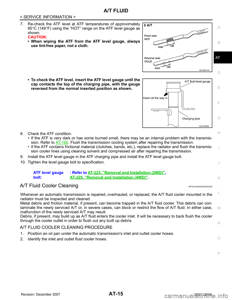
7. Re-check the ATF level at ATF temperatures of approximately
65°C (149°F) using the “HOT” range on the ATF level gauge as
shown.
CAUTION:
• When wiping the ATF from the ATF level gauge, always
use lint-free paper, not a cloth.
• To check the ATF level, insert the ATF level gauge until the
cap contacts the top of the charging pipe, with the gauge
reversed from the normal inserted position as shown.
8. Check the ATF condition.
• If the ATF is very dark or has some burned smell, there may be an internal problem with the transmis-
sion. Refer to AT-165
. Flush the transmission cooling system after repairing the transmission.
• If the ATF contains frictional material (clutches, bands, etc.), replace the radiator and flush the transmis-
sion cooler lines using cleaning solvent and compressed air after repairing the transmission.
9. Install the ATF level gauge in the ATF charging pipe and install the ATF level gauge bolt.
10. Tighten the level gauge bolt to specification.
A/T Fluid Cooler CleaningINFOID:0000000003532226
Whenever an automatic transmission is repaired, overhauled, or replaced, the A/T fluid cooler mounted in the
radiator must be inspected and cleaned.
Metal debris and friction material, if present, can become trapped in the A/T fluid cooler. This debris can con-
taminate the newly serviced A/T or, in severe cases, can block or restrict the flow of A/T fluid. In either case,
malfunction of the newly serviced A/T may result.
Debris, if present, may build up as A/T fluid enters the cooler inlet. It will be necessary to back flush the cooler
through the cooler outlet in order to flush out any built up debris.
A/T FLUID COOLER CLEANING PROCEDURE
1. Position an oil pan under the automatic transmission's inlet and outlet cooler hoses.
2. Identify the inlet and outlet fluid cooler hoses.
WLIA0014E
SCIA1684E
ATF level gauge
bolt:: Refer to AT-223, "Removal and Installation (2WD)",
AT-225, "
Removal and Installation (4WD)".
Page 86 of 3061
AT-16
< SERVICE INFORMATION >
A/T FLUID
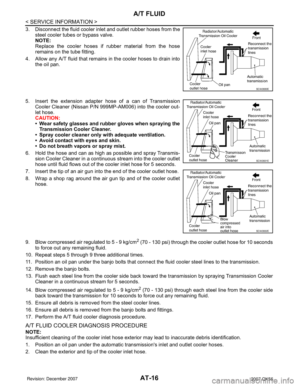
3. Disconnect the fluid cooler inlet and outlet rubber hoses from the
steel cooler tubes or bypass valve.
NOTE:
Replace the cooler hoses if rubber material from the hose
remains on the tube fitting.
4. Allow any A/T fluid that remains in the cooler hoses to drain into
the oil pan.
5. Insert the extension adapter hose of a can of Transmission
Cooler Cleaner (Nissan P/N 999MP-AM006) into the cooler out-
let hose.
CAUTION:
• Wear safety glasses and rubber gloves when spraying the
Transmission Cooler Cleaner.
• Spray cooler cleaner only with adequate ventilation.
• Avoid contact with eyes and skin.
• Do not breath vapors or spray mist.
6. Hold the hose and can as high as possible and spray Transmis-
sion Cooler Cleaner in a continuous stream into the cooler outlet
hose until fluid flows out of the cooler inlet hose for 5 seconds.
7. Insert the tip of an air gun into the end of the cooler outlet hose.
8. Wrap a shop rag around the air gun tip and of the cooler outlet
hose.
9. Blow compressed air regulated to 5 - 9 kg/cm
2 (70 - 130 psi) through the cooler outlet hose for 10 seconds
to force out any remaining fluid.
10. Repeat steps 5 through 9 three additional times.
11. Position an oil pan under the banjo bolts that connect the fluid cooler steel lines to the transmission.
12. Remove the banjo bolts.
13. Flush each steel line from the cooler side back toward the transmission by spraying Transmission Cooler
Cleaner in a continuous stream for 5 seconds.
14. Blow compressed air regulated to 5 - 9 kg/cm
2 (70 - 130 psi) through each steel line from the cooler side
back toward the transmission for 10 seconds to force out any remaining fluid.
15. Ensure all debris is removed from the steel cooler lines.
16. Ensure all debris is removed from the banjo bolts and fittings.
17. Perform the A/T fluid cooler diagnosis procedure.
A/T FLUID COOLER DIAGNOSIS PROCEDURE
NOTE:
Insufficient cleaning of the cooler inlet hose exterior may lead to inaccurate debris identification.
1. Position an oil pan under the automatic transmission's inlet and outlet cooler hoses.
2. Clean the exterior and tip of the cooler inlet hose.
SCIA3830E
SCIA3831E
SCIA3832E
Page 88 of 3061
AT-18
< SERVICE INFORMATION >
A/T FLUID
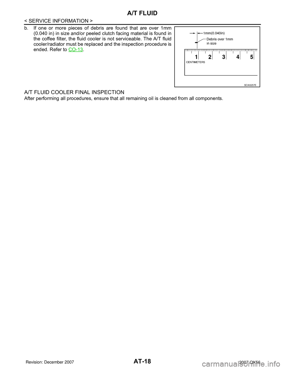
b. If one or more pieces of debris are found that are over 1mm
(0.040 in) in size and/or peeled clutch facing material is found in
the coffee filter, the fluid cooler is not serviceable. The A/T fluid
cooler/radiator must be replaced and the inspection procedure is
ended. Refer to CO-13
.
A/T FLUID COOLER FINAL INSPECTION
After performing all procedures, ensure that all remaining oil is cleaned from all components.
SCIA5257E
Page 89 of 3061
A/T CONTROL SYSTEM
AT-19
< SERVICE INFORMATION >
D
E
F
G
H
I
J
K
L
MA
B
AT
N
O
P
A/T CONTROL SYSTEM
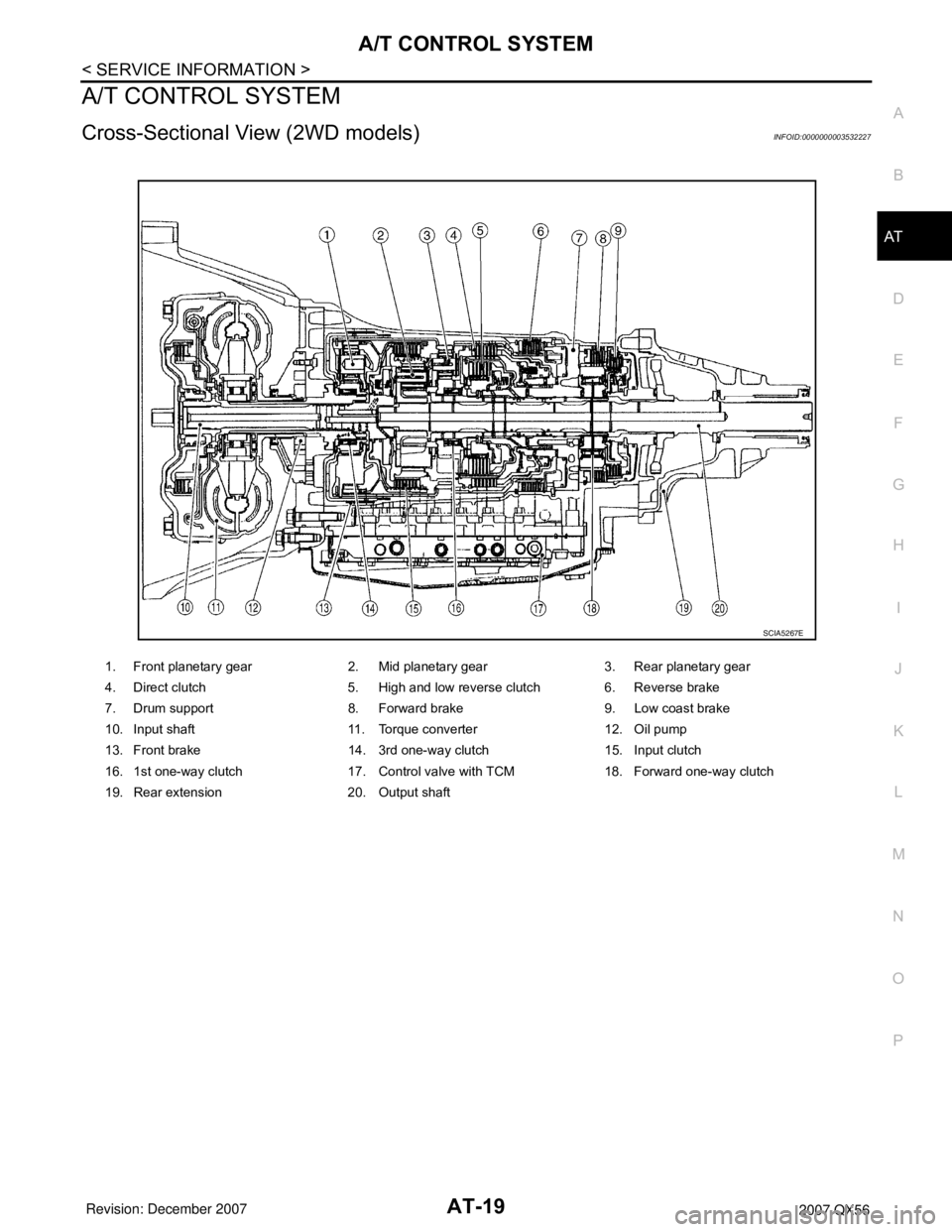
Cross-Sectional View (2WD models)INFOID:0000000003532227
1. Front planetary gear 2. Mid planetary gear 3. Rear planetary gear
4. Direct clutch 5. High and low reverse clutch 6. Reverse brake
7. Drum support 8. Forward brake 9. Low coast brake
10. Input shaft 11. Torque converter 12. Oil pump
13. Front brake 14. 3rd one-way clutch 15. Input clutch
16. 1st one-way clutch 17. Control valve with TCM 18. Forward one-way clutch
19. Rear extension 20. Output shaft
SCIA5267E
Page 90 of 3061
AT-20
< SERVICE INFORMATION >
A/T CONTROL SYSTEM
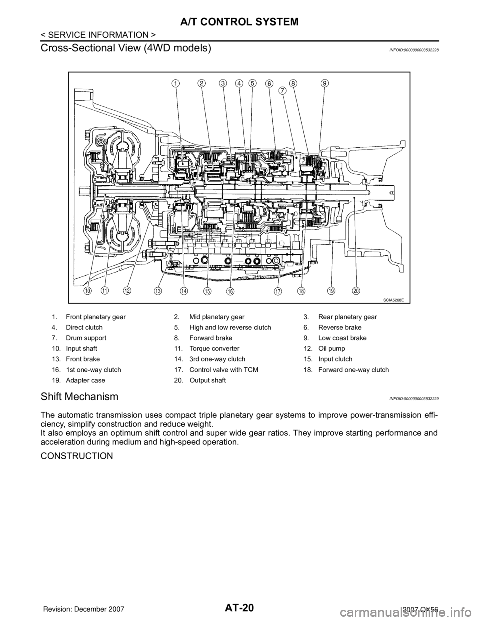
Cross-Sectional View (4WD models)
INFOID:0000000003532228
Shift MechanismINFOID:0000000003532229
The automatic transmission uses compact triple planetary gear systems to improve power-transmission effi-
ciency, simplify construction and reduce weight.
It also employs an optimum shift control and super wide gear ratios. They improve starting performance and
acceleration during medium and high-speed operation.
CONSTRUCTION
1. Front planetary gear 2. Mid planetary gear 3. Rear planetary gear
4. Direct clutch 5. High and low reverse clutch 6. Reverse brake
7. Drum support 8. Forward brake 9. Low coast brake
10. Input shaft 11. Torque converter 12. Oil pump
13. Front brake 14. 3rd one-way clutch 15. Input clutch
16. 1st one-way clutch 17. Control valve with TCM 18. Forward one-way clutch
19. Adapter case 20. Output shaft
SCIA5268E
Page 104 of 3061
AT-34
< SERVICE INFORMATION >
A/T CONTROL SYSTEM
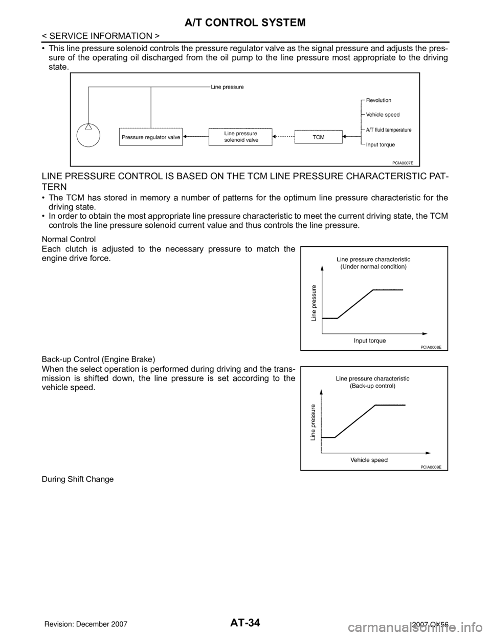
• This line pressure solenoid controls the pressure regulator valve as the signal pressure and adjusts the pres-
sure of the operating oil discharged from the oil pump to the line pressure most appropriate to the driving
state.
LINE PRESSURE CONTROL IS BASED ON THE TCM LINE PRESSURE CHARACTERISTIC PAT-
TERN
• The TCM has stored in memory a number of patterns for the optimum line pressure characteristic for the
driving state.
• In order to obtain the most appropriate line pressure characteristic to meet the current driving state, the TCM
controls the line pressure solenoid current value and thus controls the line pressure.
Normal Control
Each clutch is adjusted to the necessary pressure to match the
engine drive force.
Back-up Control (Engine Brake)
When the select operation is performed during driving and the trans-
mission is shifted down, the line pressure is set according to the
vehicle speed.
During Shift Change
PCIA0007E
PCIA0008E
PCIA0009E
Page 105 of 3061
A/T CONTROL SYSTEM
AT-35
< SERVICE INFORMATION >
D
E
F
G
H
I
J
K
L
MA
B
AT
N
O
P
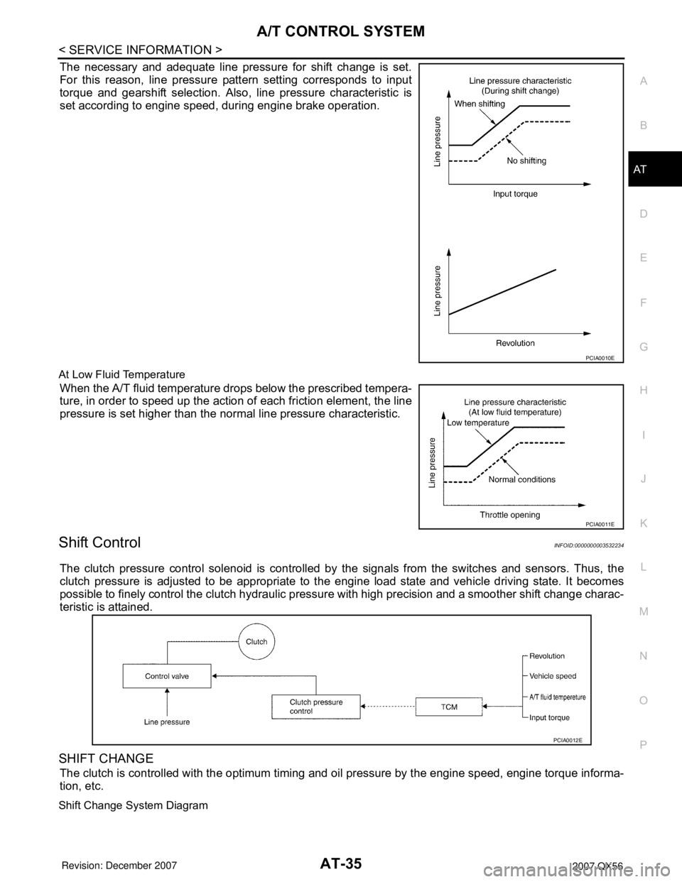
The necessary and adequate line pressure for shift change is set.
For this reason, line pressure pattern setting corresponds to input
torque and gearshift selection. Also, line pressure characteristic is
set according to engine speed, during engine brake operation.
At Low Fluid Temperature
When the A/T fluid temperature drops below the prescribed tempera-
ture, in order to speed up the action of each friction element, the line
pressure is set higher than the normal line pressure characteristic.
Shift ControlINFOID:0000000003532234
The clutch pressure control solenoid is controlled by the signals from the switches and sensors. Thus, the
clutch pressure is adjusted to be appropriate to the engine load state and vehicle driving state. It becomes
possible to finely control the clutch hydraulic pressure with high precision and a smoother shift change charac-
teristic is attained.
SHIFT CHANGE
The clutch is controlled with the optimum timing and oil pressure by the engine speed, engine torque informa-
tion, etc.
Shift Change System Diagram
PCIA0010E
PCIA0011E
PCIA0012E
Page 106 of 3061
AT-36
< SERVICE INFORMATION >
A/T CONTROL SYSTEM
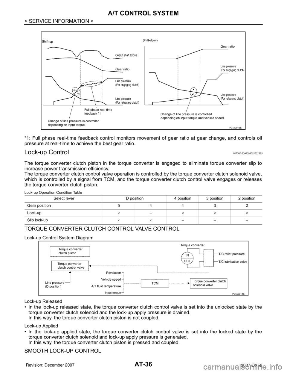
*1: Full phase real-time feedback control monitors movement of gear ratio at gear change, and controls oil
pressure at real-time to achieve the best gear ratio.
Lock-up ControlINFOID:0000000003532235
The torque converter clutch piston in the torque converter is engaged to eliminate torque converter slip to
increase power transmission efficiency.
The torque converter clutch control valve operation is controlled by the torque converter clutch solenoid valve,
which is controlled by a signal from TCM, and the torque converter clutch control valve engages or releases
the torque converter clutch piston.
Lock-up Operation Condition Table
TORQUE CONVERTER CLUTCH CONTROL VALVE CONTROL
Lock-up Control System Diagram
Lock-up Released
• In the lock-up released state, the torque converter clutch control valve is set into the unlocked state by the
torque converter clutch solenoid and the lock-up apply pressure is drained.
In this way, the torque converter clutch piston is not coupled.
Lock-up Applied
• In the lock-up applied state, the torque converter clutch control valve is set into the locked state by the
torque converter clutch solenoid and lock-up apply pressure is generated.
In this way, the torque converter clutch piston is pressed and coupled.
SMOOTH LOCK-UP CONTROL
PCIA0013E
Select lever D position 4 position 3 position 2 position
Gear position 5 4 4 3 2
Lock-up×–×××
Slip lock-up××–––
PCIA0014E
Page 107 of 3061
A/T CONTROL SYSTEM
AT-37
< SERVICE INFORMATION >
D
E
F
G
H
I
J
K
L
MA
B
AT
N
O
P
When shifting from the lock-up released state to the lock-up applied state, the current output to the torque con-
verter clutch solenoid is controlled with the TCM. In this way, when shifting to the lock-up applied state, the
torque converter clutch is temporarily set to the half-clutched state to reduce the shock.
Half-clutched State
• The current output from the TCM to the torque converter clutch solenoid is varied to gradually increase the
torque converter clutch solenoid pressure.
In this way, the lock-up apply pressure gradually rises and while the torque converter clutch piston is put into
half-clutched status, the torque converter clutch piston operating pressure is increased and the coupling is
completed smoothly.
Slip Lock-up Control
• In the slip region, the torque converter clutch solenoid current is controlled with the TCM to put it into the
half-clutched state. This absorbs the engine torque fluctuation and lock-up operates from low speed.
This raises the fuel efficiency for 4th and 5th gears at both low speed and when the accelerator has a low
degree of opening.
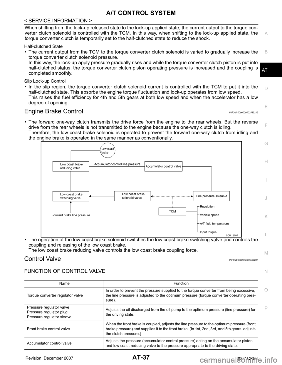
Engine Brake ControlINFOID:0000000003532236
• The forward one-way clutch transmits the drive force from the engine to the rear wheels. But the reverse
drive from the rear wheels is not transmitted to the engine because the one-way clutch is idling.
Therefore, the low coast brake solenoid is operated to prevent the forward one-way clutch from idling and
the engine brake is operated in the same manner as conventionally.
• The operation of the low coast brake solenoid switches the low coast brake switching valve and controls the
coupling and releasing of the low coast brake.
The low coast brake reducing valve controls the low coast brake coupling force.
Control ValveINFOID:0000000003532237
FUNCTION OF CONTROL VALVE
SCIA1520E
Name Function
Torque converter regulator valveIn order to prevent the pressure supplied to the torque converter from being excessive,
the line pressure is adjusted to the optimum pressure (torque converter operating pres-
sure).
Pressure regulator valve
Pressure regulator plug
Pressure regulator sleeveAdjusts the oil discharged from the oil pump to the optimum pressure (line pressure) for
the driving state.
Front brake control valveWhen the front brake is coupled, adjusts the line pressure to the optimum pressure (front
brake pressure) and supplies it to the front brake. (In 1st, 2nd, 3rd, and 5th gears, adjusts
the clutch pressure.)
Accumulator control valveAdjusts the pressure (accumulator control pressure) acting on the accumulator piston
and low coast reducing valve to the pressure appropriate to the driving state.
Page 108 of 3061

AT-38
< SERVICE INFORMATION >
A/T CONTROL SYSTEM
FUNCTION OF PRESSURE SWITCH
Pilot valve AAdjusts the line pressure and produces the constant pressure (pilot pressure) required
for line pressure control, shift change control, and lock-up control.
Pilot valve BAdjusts the line pressure and produces the constant pressure (pilot pressure) required
for shift change control.
Low coast brake switching valve During engine braking, supplies the line pressure to the low coast brake reducing valve.
Low coast brake reducing valveWhen the low coast brake is coupled, adjusts the line pressure to the optimum pressure
(low coast brake pressure) and supplies it to the low coast brake.
N-R accumulator Produces the stabilizing pressure for when N-R is selected.
Direct clutch piston switching valve Operates in 4th gear and switches the direct clutch coupling capacity.
High and low reverse clutch control valveWhen the high and low reverse clutch is coupled, adjusts the line pressure to the opti-
mum pressure (high and low reverse clutch pressure) and supplies it to the high and low
reverse clutch. (In 1st, 3rd, 4th and 5th gears, adjusts the clutch pressure.)
Input clutch control valveWhen the input clutch is coupled, adjusts the line pressure to the optimum pressure (in-
put clutch pressure) and supplies it to the input clutch. (In 4th and 5th gears, adjusts the
clutch pressure.)
Direct clutch control valveWhen the direct clutch is coupled, adjusts the line pressure to the optimum pressure (di-
rect clutch pressure) and supplies it to the direct clutch. (In 2nd, 3rd, and 4th gears, ad-
justs the clutch pressure.)
TCC control valve
TCC control plug
TCC control sleeveSwitches the lock-up to operating or released. Also, by performing the lock-up operation
transiently, lock-up smoothly.
Torque converter lubrication valveOperates during lock-up to switch the torque converter, cooling, and lubrication system
oil path.
Cool bypass valve Allows excess oil to bypass cooler circuit without being fed into it.
Line pressure relief valve Discharges excess oil from line pressure circuit.
N-D accumulator Produces the stabilizing pressure for when N-D is selected.
Manual valveSends line pressure to each circuit according to the select position. The circuits to which
the line pressure is not sent drain. Name Function
Name Function
Pressure switch 1 (FR/B)Detects any malfunction in the front brake hydraulic pressure. When it detects any mal-
function, it puts the system into fail-safe mode.
Pressure switch 2 (LC/B)Detects any malfunction in the low coast brake hydraulic pressure. When it detects any
malfunction, it puts the system into fail-safe mode.
Pressure switch 3 (I/C)Detects any malfunction in the input clutch hydraulic pressure. When it detects any mal-
function, it puts the system into fail-safe mode.
Pressure switch 5 (D/C)Detects any malfunction in the direct clutch hydraulic pressure. When it detects any mal-
function, it puts the system into fail-safe mode.
Pressure switch 6 (HLR/C)Detects any malfunction in the high and low reverse clutch hydraulic pressure. When it
detects any malfunction, it puts the system into fail-safe mode.