oil capacity INFINITI QX56 2007 Factory User Guide
[x] Cancel search | Manufacturer: INFINITI, Model Year: 2007, Model line: QX56, Model: INFINITI QX56 2007Pages: 3061, PDF Size: 64.56 MB
Page 2362 of 3061

SERVICE DATA AND SPECIFICATIONS (SDS)
LU-17
< SERVICE INFORMATION >
C
D
E
F
G
H
I
J
K
L
MA
LU
N
P O
SERVICE DATA AND SPECIFICATIONS (SDS)
Standard and LimitINFOID:0000000003531561
OIL PRESSURE
Unit: kPa (kg/cm2
, psi)
OIL PUMP
Unit: mm (in)
REGULATOR VALVE
Unit: mm (in)
ENGINE OIL CAPACITY (APPROXIMATE)
Unit: (US qt, Imp qt)
Engine speed
rpm Approximate discharge oil pressure
Idle speed
2,000More than 98 (1.0, 14)
More than 294 (3.0, 43)
Body to outer rotor radial clearance 0.114 - 0.200 (0.0045 - 0.0079)
Inner rotor to outer rotor tip clearance Below 0.180 (0.0071)
Body to inner rotor side clearance 0.030 - 0.070 (0.0012 - 0.0028)
Body to outer rotor side clearance 0.030 - 0.090 (0.0012 - 0.0035)
Inner rotor to brazed portion of housing clearance 0.045 - 0.091 (0.0018 - 0.0036)
Regulator valve to oil pump cover clearance 0.040 - 0.097 (0.0016 - 0.0038)
Drain and refillWith oil filter change 6.2 (6 1/2, 5-1/2)
Without oil filter change 5.9 (6-1/4, 5-1/4)
Dry engine (engine overhaul) 7.6 (8, 6-3/4)
Page 2372 of 3061
MA-10
< SERVICE INFORMATION >
RECOMMENDED FLUIDS AND LUBRICANTS
RECOMMENDED FLUIDS AND LUBRICANTS
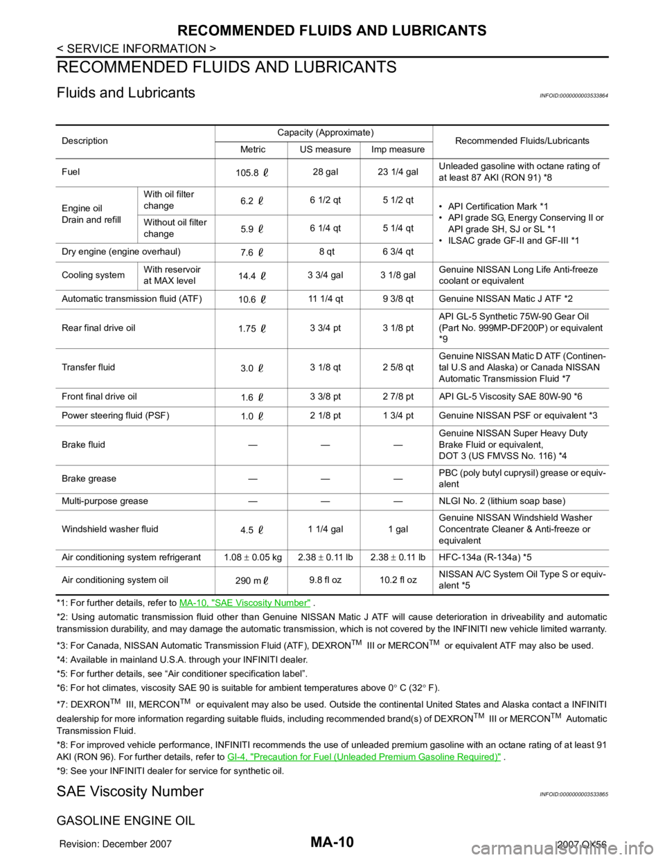
Fluids and LubricantsINFOID:0000000003533864
*1: For further details, refer to MA-10, "SAE Viscosity Number" .
*2: Using automatic transmission fluid other than Genuine NISSAN Matic J ATF will cause deterioration in driveability and automatic
transmission durability, and may damage the automatic transmission, which is not covered by the INFINITI new vehicle limited warranty.
*3: For Canada, NISSAN Automatic Transmission Fluid (ATF), DEXRON
TM III or MERCONTM or equivalent ATF may also be used.
*4: Available in mainland U.S.A. through your INFINITI dealer.
*5: For further details, see “Air conditioner specification label”.
*6: For hot climates, viscosity SAE 90 is suitable for ambient temperatures above 0° C (32° F).
*7: DEXRON
TM III, MERCONTM or equivalent may also be used. Outside the continental United States and Alaska contact a INFINITI
dealership for more information regarding suitable fluids, including recommended brand(s) of DEXRONTM III or MERCONTM Automatic
Transmission Fluid.
*8: For improved vehicle performance, INFINITI recommends the use of unleaded premium gasoline with an octane rating of at least 91
AKI (RON 96). For further details, refer to GI-4, "
Precaution for Fuel (Unleaded Premium Gasoline Required)" .
*9: See your INFINITI dealer for service for synthetic oil.
SAE Viscosity NumberINFOID:0000000003533865
GASOLINE ENGINE OIL
DescriptionCapacity (Approximate)
Recommended Fluids/Lubricants
Metric US measure Imp measure
Fuel
105.8 28 gal 23 1/4 galUnleaded gasoline with octane rating of
at least 87 AKI (RON 91) *8
Engine oil
Drain and refillWith oil filter
change6.2 6 1/2 qt 5 1/2 qt
• API Certification Mark *1
• API grade SG, Energy Conserving II or
API grade SH, SJ or SL *1
• ILSAC grade GF-II and GF-III *1 Without oil filter
change5.9 6 1/4 qt 5 1/4 qt
Dry engine (engine overhaul)
7.6 8 qt 6 3/4 qt
Cooling systemWith reservoir
at MAX level14.4 3 3/4 gal 3 1/8 galGenuine NISSAN Long Life Anti-freeze
coolant or equivalent
Automatic transmission fluid (ATF)
10.6 11 1/4 qt 9 3/8 qt Genuine NISSAN Matic J ATF *2
Rear final drive oil
1.75 3 3/4 pt 3 1/8 ptAPI GL-5 Synthetic 75W-90 Gear Oil
(Part No. 999MP-DF200P) or equivalent
*9
Transfer fluid
3.0 3 1/8 qt 2 5/8 qtGenuine NISSAN Matic D ATF (Continen-
tal U.S and Alaska) or Canada NISSAN
Automatic Transmission Fluid *7
Front final drive oil
1.6 3 3/8 pt 2 7/8 pt API GL-5 Viscosity SAE 80W-90 *6
Power steering fluid (PSF)
1.0 2 1/8 pt 1 3/4 pt Genuine NISSAN PSF or equivalent *3
Brake fluid — — —Genuine NISSAN Super Heavy Duty
Brake Fluid or equivalent,
DOT 3 (US FMVSS No. 116) *4
Brake grease — — —PBC (poly butyl cuprysil) grease or equiv-
alent
Multi-purpose grease — — — NLGI No. 2 (lithium soap base)
Windshield washer fluid
4.5 1 1/4 gal 1 galGenuine NISSAN Windshield Washer
Concentrate Cleaner & Anti-freeze or
equivalent
Air conditioning system refrigerant 1.08 ± 0.05 kg 2.38 ± 0.11 lb 2.38 ± 0.11 lb HFC-134a (R-134a) *5
Air conditioning system oil
290 m9.8 fl oz 10.2 fl ozNISSAN A/C System Oil Type S or equiv-
alent *5
Page 2378 of 3061
MA-16
< SERVICE INFORMATION >
ENGINE MAINTENANCE
2. Disconnect the harness connector, then remove the air cleaner case (upper).
3. Remove the air cleaner filter from the air cleaner case (lower).
4. Install the new air cleaner filter in the air cleaner case (lower).
5. Install the air cleaner case (upper) and connect the harness connector.
6. Install the air duct and resonator assembly.
Changing Engine OilINFOID:0000000003533871
WARNING:
• Be careful not to burn yourself, as the engine and engine oil are hot.
• Prolonged and repeated contact with used engine oil may cause skin cancer; try to avoid direct skin
contact with used oil. If skin contact is made, wash thoroughly with soap or hand cleaner as soon as
possible.
1. Warm up the engine, and check for any oil leaks.
2. Stop the engine and wait for at least 10 minutes.
3. Remove the oil drain plug and oil filler cap to drain the old oil.
4. Install a new washer on the oil drain plug, then install the oil drain plug in the oil pan.
CAUTION:
Clean the drain plug and install with a new washer.
5. Refill the engine with new specified engine oil.
CAUTION:
The refill capacity depends on the oil temperature and drain time. Use the “Refill oil capacity” val-
ues as a reference and check the oil level using the dipstick when filling the engine with oil.
6. Warm up the engine and check the area around the drain plug and oil filter for any oil leaks.
7. Stop the engine and wait for more than 10 minutes.
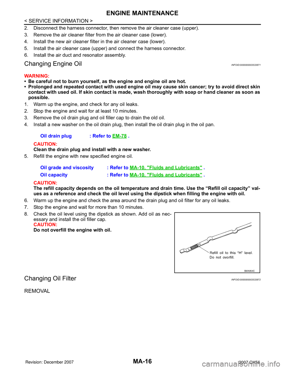
8. Check the oil level using the dipstick as shown. Add oil as nec-
essary and install the oil filler cap.
CAUTION:
Do not overfill the engine with oil.
Changing Oil FilterINFOID:0000000003533872
REMOVAL
Oil drain plug : Refer to EM-78 .
Oil grade and viscosity : Refer to MA-10, "
Fluids and Lubricants" .
Oil capacity : Refer to MA-10, "
Fluids and Lubricants" .
SMA954C
Page 2385 of 3061
CHASSIS AND BODY MAINTENANCE
MA-23
< SERVICE INFORMATION >
C
D
E
F
G
H
I
J
K
MA
B
MA
N
O
P
10. Tighten the level gauge bolt to specification.
Changing Automatic Transmission Fluid (ATF)INFOID:0000000003533878
1. Drive the vehicle to warm up the ATF to 80° C (176° F).
2. Stop the engine.
3. Remove the ATF level gauge bolt.
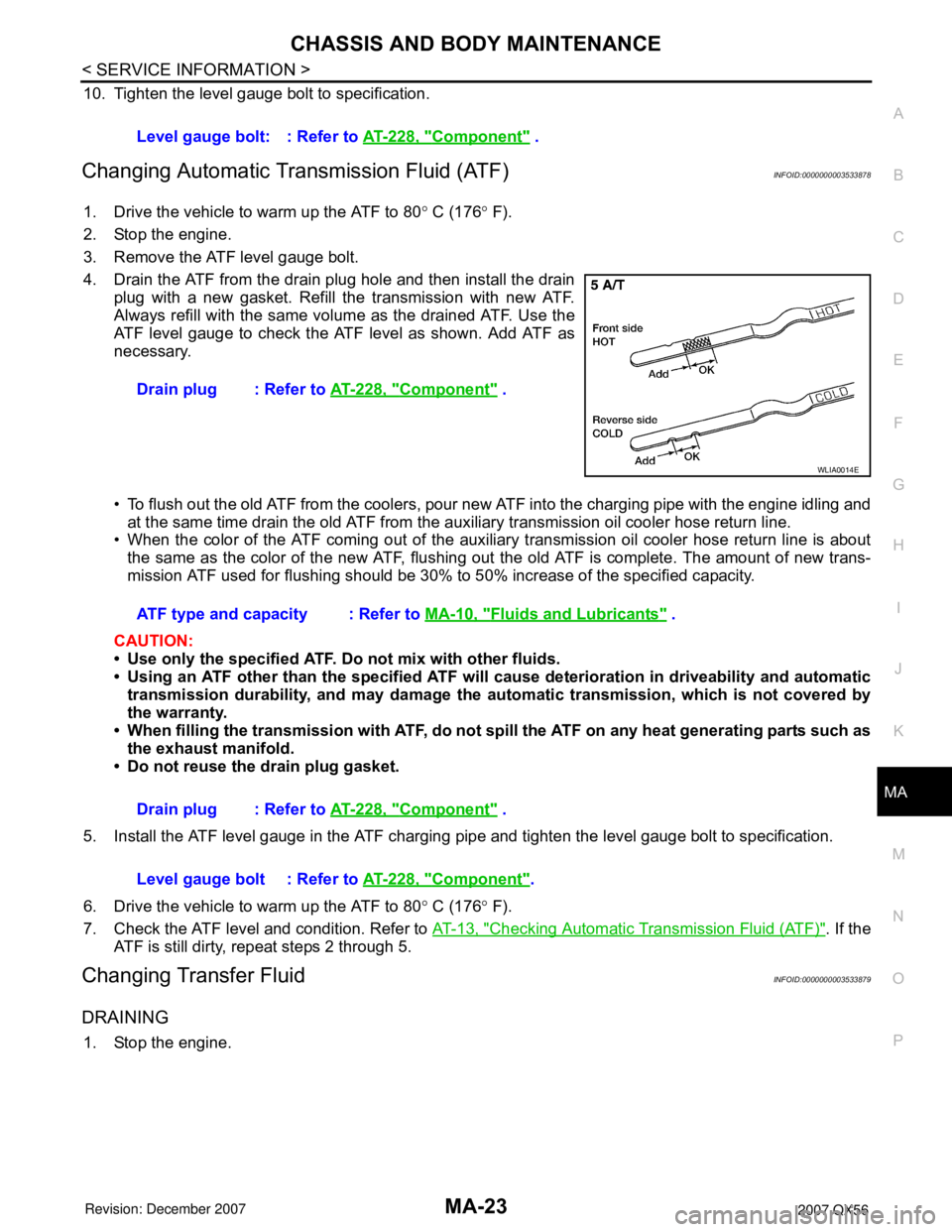
4. Drain the ATF from the drain plug hole and then install the drain
plug with a new gasket. Refill the transmission with new ATF.
Always refill with the same volume as the drained ATF. Use the
ATF level gauge to check the ATF level as shown. Add ATF as
necessary.
• To flush out the old ATF from the coolers, pour new ATF into the charging pipe with the engine idling and
at the same time drain the old ATF from the auxiliary transmission oil cooler hose return line.
• When the color of the ATF coming out of the auxiliary transmission oil cooler hose return line is about
the same as the color of the new ATF, flushing out the old ATF is complete. The amount of new trans-
mission ATF used for flushing should be 30% to 50% increase of the specified capacity.
CAUTION:
• Use only the specified ATF. Do not mix with other fluids.
• Using an ATF other than the specified ATF will cause deterioration in driveability and automatic
transmission durability, and may damage the automatic transmission, which is not covered by
the warranty.
• When filling the transmission with ATF, do not spill the ATF on any heat generating parts such as
the exhaust manifold.
• Do not reuse the drain plug gasket.
5. Install the ATF level gauge in the ATF charging pipe and tighten the level gauge bolt to specification.
6. Drive the vehicle to warm up the ATF to 80° C (176° F).
7. Check the ATF level and condition. Refer to AT-13, "
Checking Automatic Transmission Fluid (ATF)". If the
ATF is still dirty, repeat steps 2 through 5.
Changing Transfer FluidINFOID:0000000003533879
DRAINING
1. Stop the engine.Level gauge bolt: : Refer to AT-228, "
Component" .
Drain plug : Refer to AT-228, "
Component" .
WLIA0014E
ATF type and capacity : Refer to MA-10, "Fluids and Lubricants" .
Drain plug : Refer to AT-228, "
Component" .
Level gauge bolt : Refer to AT-228, "
Component".
Page 2386 of 3061
MA-24
< SERVICE INFORMATION >
CHASSIS AND BODY MAINTENANCE
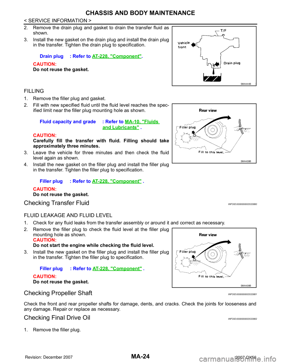
2. Remove the drain plug and gasket to drain the transfer fluid as
shown.
3. Install the new gasket on the drain plug and install the drain plug
in the transfer. Tighten the drain plug to specification.
CAUTION:
Do not reuse the gasket.
FILLING
1. Remove the filler plug and gasket.
2. Fill with new specified fluid until the fluid level reaches the spec-
ified limit near the filler plug mounting hole as shown.
CAUTION:
Carefully fill the transfer with fluid. Filling should take
approximately three minutes.
3. Leave the vehicle for three minutes and then check the fluid
level again as shown.
4. Install the new gasket on the filler plug and install the filler plug
in the transfer. Tighten the filler plug to specification.
CAUTION:
Do not reuse the gasket.
Checking Transfer FluidINFOID:0000000003533880
FLUID LEAKAGE AND FLUID LEVEL
1. Check for any fluid leaks from the transfer assembly or around it and correct as necessary.
2. Remove the filler plug to check the fluid level at the filler plug
mounting hole as shown.
CAUTION:
Do not start the engine while checking the fluid level.
3. Install the new gasket on the filler plug and install the filler plug
in the transfer. Tighten the filler plug to specification.
CAUTION:
Do not reuse the gasket.
Checking Propeller ShaftINFOID:0000000003533881
Check the front and rear propeller shafts for damage, dents, and cracks. Check the joints for looseness and
any damage. Repair or replace as necessary.
Checking Final Drive OilINFOID:0000000003533882
1. Remove the filler plug.Drain plug : Refer to AT-228, "
Component".
SMA444B
Fluid capacity and grade : Refer to MA-10, "Fluids
and Lubricants" .
Filler plug : Refer to AT-228, "
Component" .
SMA439B
Filler plug : Refer to AT-228, "Component" .
SMA439B
Page 2387 of 3061
CHASSIS AND BODY MAINTENANCE
MA-25
< SERVICE INFORMATION >
C
D
E
F
G
H
I
J
K
MA
B
MA
N
O
P
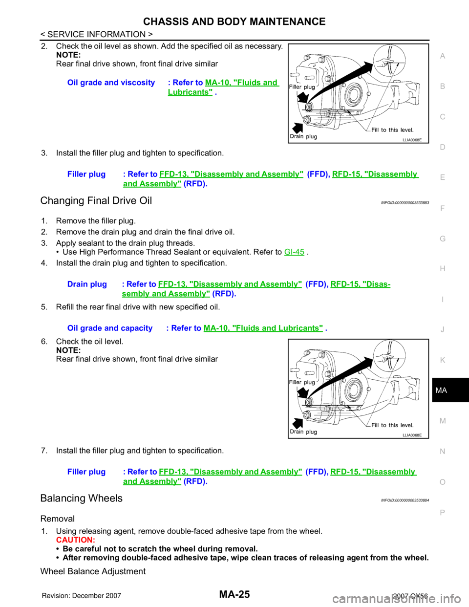
2. Check the oil level as shown. Add the specified oil as necessary.
NOTE:
Rear final drive shown, front final drive similar
3. Install the filler plug and tighten to specification.
Changing Final Drive OilINFOID:0000000003533883
1. Remove the filler plug.
2. Remove the drain plug and drain the final drive oil.
3. Apply sealant to the drain plug threads.
• Use High Performance Thread Sealant or equivalent. Refer to GI-45
.
4. Install the drain plug and tighten to specification.
5. Refill the rear final drive with new specified oil.
6. Check the oil level.
NOTE:
Rear final drive shown, front final drive similar
7. Install the filler plug and tighten to specification.
Balancing WheelsINFOID:0000000003533884
Removal
1. Using releasing agent, remove double-faced adhesive tape from the wheel.
CAUTION:
• Be careful not to scratch the wheel during removal.
• After removing double-faced adhesive tape, wipe clean traces of releasing agent from the wheel.
Wheel Balance Adjustment
Oil grade and viscosity : Refer to MA-10, "Fluids and
Lubricants" .
LLIA0068E
Filler plug : Refer to FFD-13, "Disassembly and Assembly" (FFD), RFD-15, "Disassembly
and Assembly" (RFD).
Drain plug : Refer to FFD-13, "
Disassembly and Assembly" ( F F D ) , RFD-15, "Disas-
sembly and Assembly" (RFD).
Oil grade and capacity : Refer to MA-10, "
Fluids and Lubricants" .
LLIA0068E
Filler plug : Refer to FFD-13, "Disassembly and Assembly" ( F F D ) , RFD-15, "Disassembly
and Assembly" (RFD).
Page 2518 of 3061

SERVICE DATA AND SPECIFICATIONS (SDS)
PS-27
< SERVICE INFORMATION >
C
D
E
F
H
I
J
K
L
MA
B
PS
N
O
P
Oil PumpINFOID:0000000003532839
Steering FluidINFOID:0000000003532840
Rack sliding forceAt the neutral point:
Range within ± 11.5 mm
(±0.453 in) from the neutral
position
(in power ON)Area average value 147 − 211 N (14.99 − 21.52 kg, 33.1 − 47.52 lb)
Allowable variation 98 N (10 kg, 22 lb) or less
Whole area (in power OFF)Peak value 294 N (30.0 kg, 66 lb) or less
Allowable variation 147 N (16 kg, 35 lb) or less Steering gear modelPR26AM
Relief oil pressure
9.0 − 9.8 mPa (91.77 − 99.93 kg/cm2, 1305.34 − 1421.37 psi)
Fluid capacity
Approx. 1.0 (1-1/8 US qt, 7/8 Imp qt)
Page 2565 of 3061
RFD-8
< SERVICE INFORMATION >
DIFFERENTIAL GEAR OIL
DIFFERENTIAL GEAR OIL
Changing Differential Gear OilINFOID:0000000003532601
DRAINING
1. Stop the engine.
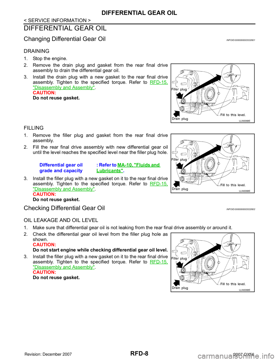
2. Remove the drain plug and gasket from the rear final drive
assembly to drain the differential gear oil.
3. Install the drain plug with a new gasket to the rear final drive
assembly. Tighten to the specified torque. Refer to RFD-15,
"Disassembly and Assembly".
CAUTION:
Do not reuse gasket.
FILLING
1. Remove the filler plug and gasket from the rear final drive
assembly.
2. Fill the rear final drive assembly with new differential gear oil
until the level reaches the specified level near the filler plug hole.
3. Install the filler plug with a new gasket on it to the rear final drive
assembly. Tighten to the specified torque. Refer to RFD-15,
"Disassembly and Assembly".
CAUTION:
Do not reuse gasket.
Checking Differential Gear OilINFOID:0000000003532602
OIL LEAKAGE AND OIL LEVEL
1. Make sure that differential gear oil is not leaking from the rear final drive assembly or around it.
2. Check the differential gear oil level from the filler plug hole as
shown.
CAUTION:
Do not start engine while checking differential gear oil level.
3. Install the filler plug with a new gasket on it to the rear final drive
assembly. Tighten to the specified torque. Refer to RFD-15,
"Disassembly and Assembly".
CAUTION:
Do not reuse gasket.
LLIA0068E
Differential gear oil
grade and capacity: Refer to MA-10, "Fluids and
Lubricants".
LLIA0068E
LLIA0068E
Page 2589 of 3061

RFD-32
< SERVICE INFORMATION >
SERVICE DATA AND SPECIFICATIONS (SDS)
SERVICE DATA AND SPECIFICATIONS (SDS)
General SpecificationINFOID:0000000003532608
Inspection and AdjustmentINFOID:0000000003532609
DRIVE GEAR RUNOUT
Unit: mm (in)
SIDE GEAR CLEARANCE
Unit: mm (in)
PRELOAD TORQUE
Unit: N·m (kg-m, in-lb)
BACKLASH
Unit: mm (in)
COMPANION FLANGE RUNOUT
Unit: mm (in)
SELECTIVE PARTS
Side Gear Thrust Washer
Applied modelVK56DE
2WD 4WD
Final drive modelR230
Gear ratio 2.937 3.357
Number of teeth (Drive gear/Drive pinion) 47 / 16 47 / 14
Oil capacity (Approx.)
1.75 (3 3/4 US pt, 3 1/8 Imp pt)
Number of pinion gears 2
Drive pinion adjustment spacer type Collapsible
Item Runout limit
Drive gear back face0.05 (0.0020) or less
Item Specification
Side gear back clearance
(Clearance limit between side gear and differential case for adjusting
side gear backlash)0.20 (0.0079) or less
(Each gear should rotate smoothly without excessive resis-
tance during differential motion.)
Item Specification
Drive pinion bearing preload torque 1.77 − 2.64 N·m (0.18 − 0.26 kg−m, 16 − 23 in-lb)
Side bearing preload torque (reference value determined by drive
gear bolt pulling force)0.20 − 0.52 N·m (0.02 − 0.05 kg−m, 2 − 4 in-lb)
Drive gear bolt pulling force (by spring gauge) 34.2 − 39.2 N (3.5 − 4 kg, 7.7 − 8.8 lb)
Total preload torque
(Total preload torque = drive pinion bearing preload torque + Side
bearing preload torque)2.05 − 4.11 N·m (0.21 − 0.42 kg−m, 19 − 36 in-lb)
Item Specification
Drive gear to drive pinion gear 0.13 − 0.18 (0.0051 − 0.0070)
Item Runout limit
Outer side of the companion flange 0.08 (0.0031) or less
Page 2988 of 3061

TF-166
< SERVICE INFORMATION >
SERVICE DATA AND SPECIFICATIONS (SDS)
SERVICE DATA AND SPECIFICATIONS (SDS)
General SpecificationINFOID:0000000003532572
Inspection and AdjustmentINFOID:0000000003532573
CLEARANCE BETWEEN INNER GEAR AND OUTER GEAR
Unit: mm (in)
CLUTCH
Unit: mm (in)
PINION GEAR END PLAY
Unit: mm (in)
CLEARANCE BETWEEN SHIFT FORK AND SLEEVE
Unit: mm (in)
SELECTIVE PARTS
Sub-oil Pump
Unit: mm (in)
*: Always check with the Parts Department for the latest parts information.
Main Oil Pump
Applied modelVK56DE
Transfer modelAT X 1 4 B
Fluid capacity (Approx.)
(US qt, lmp qt)3.0 (3-1/8, 2-5/8)
Gear ratioHigh 1.000
Low 2.596
Number of teethSun gear 57
Internal gear 91
Front drive sprocket 38
Front drive shaft 38
Item Specification
Main oil pump 0.015 - 0.035 (0.0006 - 0.0014)
Sub-oil pump 0.015 - 0.035 (0.0006 - 0.0014)
Item Limit value
Drive plate1.4 (0.055)
Item Standard
Pinion gear end play 0.1 - 0.7 (0.004 - 0.028)
Item Standard
Shift fork and sleeve Less than 0.36 (0.0142)
Gear thicknessPart number*
Inner gear Outer gear
9.27 - 9.28 (0.3650 - 0.3654) 31346 0W462 31347 0W462
9.28 - 9.29 (0.3654 - 0.3657) 31346 0W461 31347 0W461
9.29 - 9.30 (0.3657 - 0.3661) 31346 0W460 31347 0W460