oil type INFINITI QX56 2007 Factory User Guide
[x] Cancel search | Manufacturer: INFINITI, Model Year: 2007, Model line: QX56, Model: INFINITI QX56 2007Pages: 3061, PDF Size: 64.56 MB
Page 1005 of 3061
CO-16
< SERVICE INFORMATION >
ENGINE COOLING FAN
ENGINE COOLING FAN
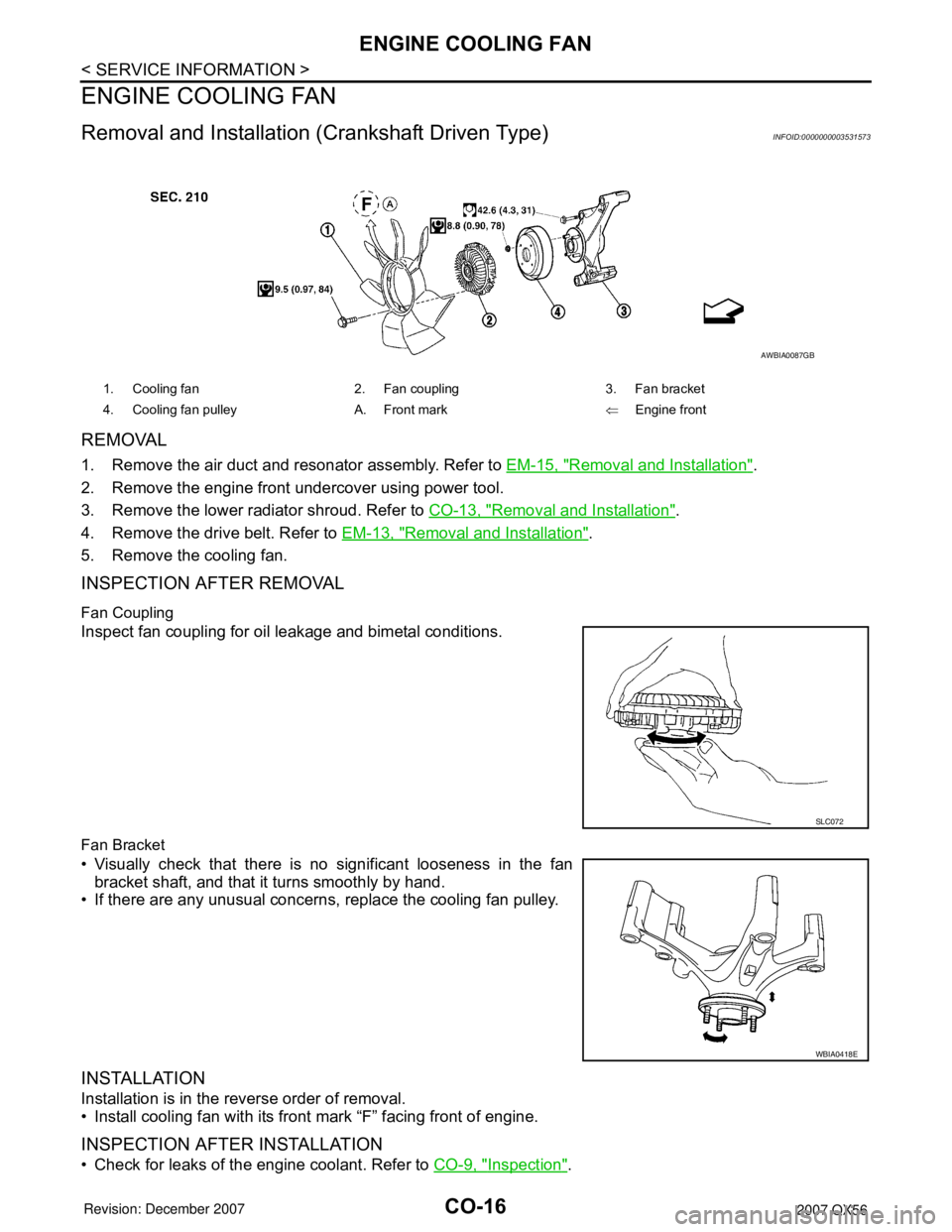
Removal and Installation (Crankshaft Driven Type)INFOID:0000000003531573
REMOVAL
1. Remove the air duct and resonator assembly. Refer to EM-15, "Removal and Installation".
2. Remove the engine front undercover using power tool.
3. Remove the lower radiator shroud. Refer to CO-13, "
Removal and Installation".
4. Remove the drive belt. Refer to EM-13, "
Removal and Installation".
5. Remove the cooling fan.
INSPECTION AFTER REMOVAL
Fan Coupling
Inspect fan coupling for oil leakage and bimetal conditions.
Fan Bracket
• Visually check that there is no significant looseness in the fan
bracket shaft, and that it turns smoothly by hand.
• If there are any unusual concerns, replace the cooling fan pulley.
INSTALLATION
Installation is in the reverse order of removal.
• Install cooling fan with its front mark “F” facing front of engine.
INSPECTION AFTER INSTALLATION
• Check for leaks of the engine coolant. Refer to CO-9, "Inspection".
1. Cooling fan 2. Fan coupling 3. Fan bracket
4. Cooling fan pulley A. Front mark⇐Engine front
AWBIA0087GB
SLC072
WBIA0418E
Page 1101 of 3061

EC-18
< SERVICE INFORMATION >
PRECAUTIONS
•Do not disassemble ECM.
•If a battery cable is disconnected, the memory will return to
the ECM value.
The ECM will now start to self-control at its initial value.
Engine operation can vary slightly when the terminal is dis-
connected. However, this is not an indication of a malfunc-
tion. Do not replace parts because of a slight variation.
•If the battery is disconnected, the following emission-related
diagnostic information will be lost within 24 hours.
-Diagnostic trouble codes
-1st trip diagnostic trouble codes
-Freeze frame data
-1st trip freeze frame data
-System readiness test (SRT) codes
-Test values
•When connecting ECM harness connector, fasten it securely
with a lever as far as it will go as shown in the figure.
•When connecting or disconnecting pin connectors into or
from ECM, take care not to damage pin terminals (bend or
break).
Make sure that there are not any bends or breaks on ECM pin
terminal, when connecting pin connectors.
•Securely connect ECM harness connectors.
A poor connection can cause an extremely high (surge) volt-
age to develop in coil and condenser, thus resulting in dam-
age to ICs.
•Keep engine control system harness at least 10 cm (4 in) away
from adjacent harness, to prevent engine control system mal-
functions due to receiving external noise, degraded operation
of ICs, etc.
•Keep engine control system parts and harness dry.
•Before replacing ECM, perform ECM Terminals and Reference
Value inspection and make sure ECM functions properly.
Refer to EC-103, "
ECM Terminal and Reference Value" .
•Handle mass air flow sensor carefully to avoid damage.
•Do not disassemble mass air flow sensor.
•Do not clean mass air flow sensor with any type of detergent.
•Do not disassemble electric throttle control actuator.
•Even a slight leak in the air intake system can cause serious
incidents.
•Do not shock or jar the camshaft position sensor (PHASE),
crankshaft position sensor (POS).
PBIB1164E
BBIA0387E
PBIB0090E
MEF040D
Page 1411 of 3061

EC-328
< SERVICE INFORMATION >
DTC P0300 - P0308 MULTIPLE CYLINDER MISFIRE, NO. 1 - 8 CYLINDER MIS-
FIRE
8. Crank engine for 5 seconds or more to remove combustion gas in the cylinder.
9. Connect spark plug and harness connector to ignition coil.
10. Fix ignition coil using a rope etc. with gap of 13 - 17 mm
between the edge of the spark plug and grounded metal portion
as shown in the figure.
11. Crank engine for about 3 seconds, and check whether spark is
generated between the spark plug and the grounded metal por-
tion.
CAUTION:
• Do not approach to the spark plug and the ignition coil
within 50cm. Be careful not to get an electrical shock
while checking, because the electrical discharge voltage
becomes 20kV or more.
• It might cause to damage the ignition coil if the gap of more than 17 mm is taken.
NOTE:
When the gap is less than 13 mm, the spark might be generated even if the coil is malfunctioning.
OK or NG
OK >> GO TO 9.
NG >> GO TO 6.
6.CHECK FUNCTION OF IGNITION COIL-II
1. Turn ignition switch OFF.
2. Disconnect spark plug and connect a known-good spark plug.
3. Crank engine for about 3 seconds, and recheck whether spark is generated between the spark plug and
the grounded metal portion.
OK or NG
OK >> GO TO 7.
NG >> Check ignition coil, power transistor and their circuits. Refer to EC-626
.
7.CHECK SPARK PLUG
Check the initial spark plug for fouling, etc.
OK or NG
OK >> Replace malfunctioning spark plug(s) with standard type
one(s). For spark plug type, refer to EM-29
.
NG >> 1. Repair or clean spark plug.
2. GO TO 8.
8.CHECK FUNCTION OF IGNITION COIL-III
1. Reconnect the initial spark plugs.
2. Crank engine for about 3 seconds, and recheck whether spark is generated between the spark plug and
the grounded portion.
OK or NG
OK >>INSPECTION END
NG >> Replace malfunctioning spark plug(s) with standard type one(s). For spark plug type, refer to EM-
29, "Removal and Installation".
9.CHECK COMPRESSION PRESSURESpark should be generated.
PBIB2325E
Spark should be generated.
SEF156I
Spark should be generated.
Page 1436 of 3061
DTC P0420, P0430 THREE WAY CATALYST FUNCTION
EC-353
< SERVICE INFORMATION >
C
D
E
F
G
H
I
J
K
L
MA
EC
N
P O
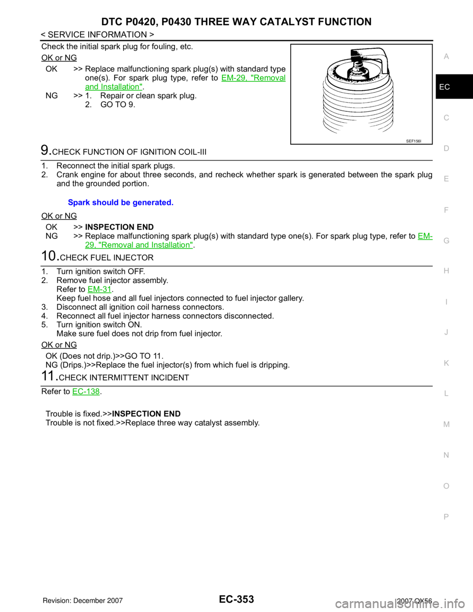
Check the initial spark plug for fouling, etc.
OK or NG
OK >> Replace malfunctioning spark plug(s) with standard type
one(s). For spark plug type, refer to EM-29, "
Removal
and Installation".
NG >> 1. Repair or clean spark plug.
2. GO TO 9.
9.CHECK FUNCTION OF IGNITION COIL-III
1. Reconnect the initial spark plugs.
2. Crank engine for about three seconds, and recheck whether spark is generated between the spark plug
and the grounded portion.
OK or NG
OK >>INSPECTION END
NG >> Replace malfunctioning spark plug(s) with standard type one(s). For spark plug type, refer to EM-
29, "Removal and Installation".
10.CHECK FUEL INJECTOR
1. Turn ignition switch OFF.
2. Remove fuel injector assembly.
Refer to EM-31
.
Keep fuel hose and all fuel injectors connected to fuel injector gallery.
3. Disconnect all ignition coil harness connectors.
4. Reconnect all fuel injector harness connectors disconnected.
5. Turn ignition switch ON.
Make sure fuel does not drip from fuel injector.
OK or NG
OK (Does not drip.)>>GO TO 11.
NG (Drips.)>>Replace the fuel injector(s) from which fuel is dripping.
11 .CHECK INTERMITTENT INCIDENT
Refer to EC-138
.
Trouble is fixed.>>INSPECTION END
Trouble is not fixed.>>Replace three way catalyst assembly.
SEF156I
Spark should be generated.
Page 1731 of 3061

EI-2
< SERVICE INFORMATION >
PRECAUTIONS
SERVICE INFORMATION
PRECAUTIONS
Service NoticeINFOID:0000000003533114
• When removing or installing various parts, place a cloth or padding on the vehicle body to prevent scratches.
• Handle trim, molding, instruments, grille, etc. carefully during removing or installing. Be careful not to soil or
damage them.
• Apply sealing compound where necessary when installing parts.
• When applying sealing compound, be careful that the sealing compound does not protrude from parts.
• When replacing any metal parts (for example body outer panel, members, etc.), be sure to take rust preven-
tion measures.
Precaution for Supplemental Restraint System (SRS) "AIR BAG" and "SEAT BELT
PRE-TENSIONER"
INFOID:0000000003533115
The Supplemental Restraint System such as “AIR BAG” and “SEAT BELT PRE-TENSIONER”, used along
with a front seat belt, helps to reduce the risk or severity of injury to the driver and front passenger for certain
types of collision. This system includes seat belt switch inputs and dual stage front air bag modules. The SRS
system uses the seat belt switches to determine the front air bag deployment, and may only deploy one front
air bag, depending on the severity of a collision and whether the front occupants are belted or unbelted.
Information necessary to service the system safely is included in the SRS and SB section of this Service Man-
ual.
WARNING:
• To avoid rendering the SRS inoperative, which could increase the risk of personal injury or death in
the event of a collision which would result in air bag inflation, all maintenance must be performed by
an authorized NISSAN/INFINITI dealer.
• Improper maintenance, including incorrect removal and installation of the SRS, can lead to personal
injury caused by unintentional activation of the system. For removal of Spiral Cable and Air Bag
Module, see the SRS section.
• Do not use electrical test equipment on any circuit related to the SRS unless instructed to in this
Service Manual. SRS wiring harnesses can be identified by yellow and/or orange harnesses or har-
ness connectors.
Page 1771 of 3061
EM-1
ENGINE
C
DE
F
G H
I
J
K L
M
SECTION EM
A
EM
N
O P
CONTENTS
ENGINE MECHANICAL
SERVICE INFORMATION .. ..........................3
PRECAUTIONS .............................................. .....3
Precaution for Supplemental Restraint System
(SRS) "AIR BAG" and "SEAT BELT PRE-TEN-
SIONER" ............................................................. ......
3
Precaution for Drain Engine Coolant .........................3
Precaution for Disconnecting Fuel Piping .................3
Precaution for Removal and Disassembly ................3
Precaution for Inspection, Repair and Replace-
ment .................................................................... ......
3
Precaution for Assembly and Installation ..................3
Parts Requiring Angular Tightening ..........................4
Precaution for Liquid Gasket ............................... ......4
PREPARATION ...................................................6
Special Service Tool ........................................... ......6
Commercial Service Tool ..........................................8
NOISE, VIBRATION AND HARSHNESS
(NVH) TROUBLESHOOTING ............................
10
NVH Troubleshooting - Engine Noise ................. ....10
Use the Chart Below to Help You Find the Cause
of the Symptom .......................................................
11
ENGINE ROOM COVER ....................................12
Removal and Installation .........................................12
DRIVE BELTS ................................................ ....13
Checking Drive Belts ........................................... ....13
Removal and Installation .........................................13
Drive Belt Auto Tensioner and Idler Pulley ......... ....14
AIR CLEANER AND AIR DUCT ........................15
Removal and Installation .........................................15
Removal and Installation (Viscous paper type) ... ....15
INTAKE MANIFOLD ...........................................17
Removal and Installation .........................................17
EXHAUST MANIFOLD AND THREE WAY
CATALYST ..................................................... ....
21
Removal and Installation ..................................... ....21
OIL PAN AND OIL STRAINER .........................24
Removal and Installation .........................................24
IGNITION COIL .................................................28
Removal and Installation .........................................28
SPARK PLUG ...................................................29
Removal and Installation .........................................29
FUEL INJECTOR AND FUEL TUBE ................31
Removal and Installation .........................................31
ROCKER COVER .............................................35
Removal and Installation .........................................35
TIMING CHAIN ..................................................37
Exploded View ..................................................... ....37
Removal and Installation .........................................38
CAMSHAFT .......................................................46
Removal and Installation .........................................46
Inspection after Installation ......................................55
Valve Clearance .................................................. ....56
OIL SEAL ..........................................................61
Removal and Installation of Valve Oil Seal ..............61
Removal and Installation of Front Oil Seal ..............61
Removal and Installation of Rear Oil Seal ...............62
CYLINDER HEAD .............................................64
On-Vehicle Service .............................................. ....64
Removal and Installation .........................................65
Disassembly and Assembly .....................................67
Inspection After Disassembly ..................................69
ENGINE ASSEMBLY ........................................74
Removal and Installation ..................................... ....74
CYLINDER BLOCK ...........................................78
Disassembly and Assembly .....................................78
How to Select Piston and Bearing ....................... ....86
Page 1773 of 3061
PRECAUTIONSEM-3
< SERVICE INFORMATION >
C
DE
F
G H
I
J
K L
M A
EM
NP
O
SERVICE INFORMATION
PRECAUTIONS
Precaution for Supplemental
Restraint System (SRS) "AIR BAG" and "SEAT BELT
PRE-TENSIONER"
INFOID:0000000003531508
The Supplemental Restraint System such as “A IR BAG” and “SEAT BELT PRE-TENSIONER”, used along
with a front seat belt, helps to reduce the risk or severi ty of injury to the driver and front passenger for certain
types of collision. This system includes seat belt switch inputs and dual stage front air bag modules. The SRS
system uses the seat belt switches to determine the front air bag deployment, and may only deploy one front
air bag, depending on the severity of a collision and w hether the front occupants are belted or unbelted.
Information necessary to service the system safely is included in the SRS and SB section of this Service Man-
ual.
WARNING:
• To avoid rendering the SRS inoper ative, which could increase the risk of personal injury or death in
the event of a collision which would result in air bag inflation, all maintenance must be performed by
an authorized NISSAN/INFINITI dealer.
• Improper maintenance, including in correct removal and installation of the SRS, can lead to personal
injury caused by unintentional act ivation of the system. For removal of Spiral Cable and Air Bag
Module, see the SRS section.
• Do not use electrical test equipm ent on any circuit related to the SRS unless instructed to in this
Service Manual. SRS wiring harnesses can be identi fied by yellow and/or orange harnesses or har-
ness connectors.
Precaution for Drain Engine CoolantINFOID:0000000003531509
Drain engine coolant when engine is cooled.
Precaution for Disco nnecting Fuel PipingINFOID:0000000003531510
• Before starting work, make sure no fire or spark producing items are in the work area.
• Release fuel pressure before disconnecting and disassembly.
• After disconnecting pipes, plug openings to stop fuel leakage.
Precaution for Removal and DisassemblyINFOID:0000000003531511
• When instructed to use special service tools, use the spec ified tools. Always be careful to work safely, avoid
forceful or uninstructed operations.
• Exercise maximum care to avoid damage to mating or sliding surfaces.
• Cover openings of engine system with tape or the equiva lent, if necessary, to seal out foreign materials.
• Mark and arrange disassembly parts in an organized way for easy troubleshooting and assembly.
• When loosening nuts and bolts, as a basic rule, start with the one furthest outside, then the one diagonally
opposite, and so on. If the order of loosening is specif ied, do exactly as specified. Power tools may be used
where noted in the step.
Precaution for Inspection, Repair and ReplacementINFOID:0000000003531512
Before repairing or replacing, thoroughly inspect parts. Inspect new replacement parts in the same way, and
replace if necessary.
Precaution for Assembly and InstallationINFOID:0000000003531513
• Use torque wrench to tighten bolts or nuts to specification.
• When tightening nuts and bolts, as a basic rule, equally tighten in several different steps starting with the ones in center, then ones on inside and outside diagonally in this order. If the order of tightening is specified,
do exactly as specified.
• Replace with new gasket, packing, oil seal or O-ring.
• Thoroughly wash, clean, and air-blow each part. Carefully check engine oil or engine coolant passages for any restriction and blockage.
• Avoid damaging sliding or mating surfaces. Completely remove foreign materials such as cloth lint or dust. Before assembly, oil sliding surfaces well.
Page 1781 of 3061
NOISE, VIBRATION AND HARSHNESS (NVH) TROUBLESHOOTINGEM-11
< SERVICE INFORMATION >
C
DE
F
G H
I
J
K L
M A
EM
NP
O
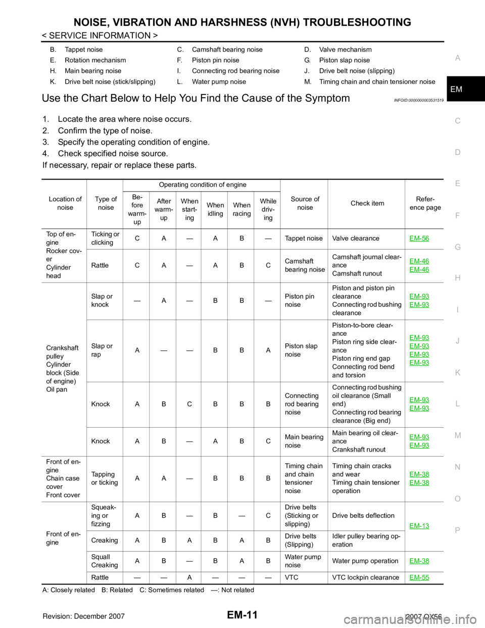
Use the Chart Below to Help You
Find the Cause of the SymptomINFOID:0000000003531519
1. Locate the area where noise occurs.
2. Confirm the type of noise.
3. Specify the operating condition of engine.
4. Check specified noise source.
If necessary, repair or replace these parts.
A: Closely related B: Related C: Sometimes related —: Not relatedB. Tappet noise C. Camshaft bearing noise D. Valve mechanism
E. Rotation mechanism F. Piston pin noise G. Piston slap noise
H. Main bearing noise I. Connecting rod bearing noise J. Drive belt noise (slipping)
K. Drive belt noise (stick/slipping) L. Water pump noise M. Timing chain and chain tensioner noise
Location of noise Ty p e o f
noise Operating condition of engine
Source of noise Check item
Refer-
ence page
Be-
fore
warm- up After
warm-
up When
start-
ing When
idling When
racing While
driv-
ing
Top of en-
gine
Rocker cov-
er
Cylinder
head Ticking or
clicking
C A — A B — Tappet noise Valve clearance
EM-56
Rattle C A — A B CCamshaft
bearing noiseCamshaft journal clear-
ance
Camshaft runout EM-46EM-46
Crankshaft
pulley
Cylinder
block (Side
of engine)
Oil panSlap or
knock
—A—B B— Piston pin
noisePiston and piston pin
clearance
Connecting rod bushing
clearance EM-93
EM-93
Slap or
rap
A——B B A Piston slap
noisePiston-to-bore clear-
ance
Piston ring side clear-
ance
Piston ring end gap
Connecting rod bend
and torsion EM-93EM-93
EM-93
EM-93
Knock A B C B B B
Connecting
rod bearing
noiseConnecting rod bushing
oil clearance (Small
end)
Connecting rod bearing
clearance (Big end)
EM-93EM-93
Knock A B — A B C
Main bearing
noiseMain bearing oil clear-
ance
Crankshaft runout EM-93EM-93
Front of en-
gine
Chain case
cover
Front coverTapping
or ticking
AA—BBB Timing chain
and chain
tensioner
noiseTiming chain cracks
and wear
Timing chain tensioner
operation
EM-38
EM-38
Front of en-
gineSqueak-
ing or
fizzing
AB—B—C
Drive belts
(Sticking or
slipping)Drive belts deflection
EM-13Creaking A B A B A B Drive belts
(Slipping)Idler pulley bearing op-
eration
Squall
Creaking AB—BAB Water pump
noiseWater pump operation
EM-38
Rattle — — A — — — VTC VTC lockpin clearance EM-55
Page 1845 of 3061
ENGINE ASSEMBLY
EM-75
< SERVICE INFORMATION >
C
D
E
F
G
H
I
J
K
L
MA
EM
N
P O
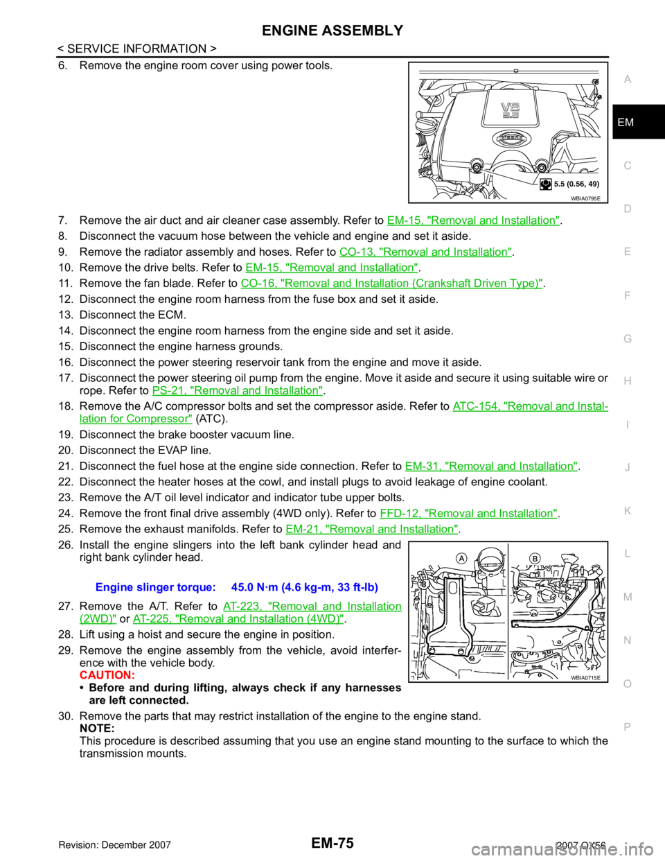
6. Remove the engine room cover using power tools.
7. Remove the air duct and air cleaner case assembly. Refer to EM-15, "
Removal and Installation".
8. Disconnect the vacuum hose between the vehicle and engine and set it aside.
9. Remove the radiator assembly and hoses. Refer to CO-13, "
Removal and Installation".
10. Remove the drive belts. Refer to EM-15, "
Removal and Installation".
11. Remove the fan blade. Refer to CO-16, "
Removal and Installation (Crankshaft Driven Type)".
12. Disconnect the engine room harness from the fuse box and set it aside.
13. Disconnect the ECM.
14. Disconnect the engine room harness from the engine side and set it aside.
15. Disconnect the engine harness grounds.
16. Disconnect the power steering reservoir tank from the engine and move it aside.
17. Disconnect the power steering oil pump from the engine. Move it aside and secure it using suitable wire or
rope. Refer to PS-21, "
Removal and Installation".
18. Remove the A/C compressor bolts and set the compressor aside. Refer to ATC-154, "
Removal and Instal-
lation for Compressor" (ATC).
19. Disconnect the brake booster vacuum line.
20. Disconnect the EVAP line.
21. Disconnect the fuel hose at the engine side connection. Refer to EM-31, "
Removal and Installation".
22. Disconnect the heater hoses at the cowl, and install plugs to avoid leakage of engine coolant.
23. Remove the A/T oil level indicator and indicator tube upper bolts.
24. Remove the front final drive assembly (4WD only). Refer to FFD-12, "
Removal and Installation".
25. Remove the exhaust manifolds. Refer to EM-21, "
Removal and Installation".
26. Install the engine slingers into the left bank cylinder head and
right bank cylinder head.
27. Remove the A/T. Refer to AT-223, "
Removal and Installation
(2WD)" or AT-225, "Removal and Installation (4WD)".
28. Lift using a hoist and secure the engine in position.
29. Remove the engine assembly from the vehicle, avoid interfer-
ence with the vehicle body.
CAUTION:
• Before and during lifting, always check if any harnesses
are left connected.
30. Remove the parts that may restrict installation of the engine to the engine stand.
NOTE:
This procedure is described assuming that you use an engine stand mounting to the surface to which the
transmission mounts.
WBIA0795E
Engine slinger torque: 45.0 N·m (4.6 kg-m, 33 ft-lb)
WBIA0715E
Page 1849 of 3061

CYLINDER BLOCK
EM-79
< SERVICE INFORMATION >
C
D
E
F
G
H
I
J
K
L
MA
EM
N
P O
DISASSEMBLY
NOTE:
Explained here is how to disassemble with engine stand supporting transmission surface. When using differ-
ent type of engine stand, some steps may be different.
1. Remove engine assembly and mount to engine stand. Refer to EM-74, "
Removal and Installation".
CAUTION:
Before removing the hanging chains, make sure engine stand is stable and there is no risk of over-
turning.
2. Drain engine oil. Refer to LU-9, "
Changing Engine Oil".
3. Drain engine coolant by removing the cylinder block drain plugs
“A”, “B”, “C” and “D” as shown.
4. Remove the following components and associated parts (the parts referred to in step 1 are not included
here).
• Oil pan (upper and lower) and oil strainer. Refer to EM-24, "
Removal and Installation".
• Crankshaft pulley, front cover and timing chain. Refer to EM-38, "
Removal and Installation".
• Camshaft. Refer to EM-46, "
Removal and Installation".
• Cylinder head. Refer to EM-65, "
Removal and Installation".
5. Remove knock sensor and sub harness.
CAUTION:
Carefully handle sensor, avoiding shocks.
6. Check connecting rod side clearance. Refer to EM-93, "
Inspection After Disassembly".
7. Remove piston and connecting rod assembly as follows.
a. Position the crankshaft pin corresponding to the connecting rod to be removed onto bottom dead center.
b. Remove connecting rod cap.
22. Drive plate 23. Reinforcement plate 24. Rear oil seal retainer
25. Rear oil seal 26. Transmission 27. O-ring
28. Crankshaft position sensor (POS) 29. Gasket 30. Cylinder block heater
31. Connector cap
WBIA0419E
KBIA2549E