brake INFINITI QX56 2007 Factory Service Manual
[x] Cancel search | Manufacturer: INFINITI, Model Year: 2007, Model line: QX56, Model: INFINITI QX56 2007Pages: 3061, PDF Size: 64.56 MB
Page 1890 of 3061
FAX-4
< SERVICE INFORMATION >
NOISE, VIBRATION AND HARSHNESS (NVH) TROUBLESHOOTING
NOISE, VIBRATION AND HARSHNESS (NVH) TROUBLESHOOTING
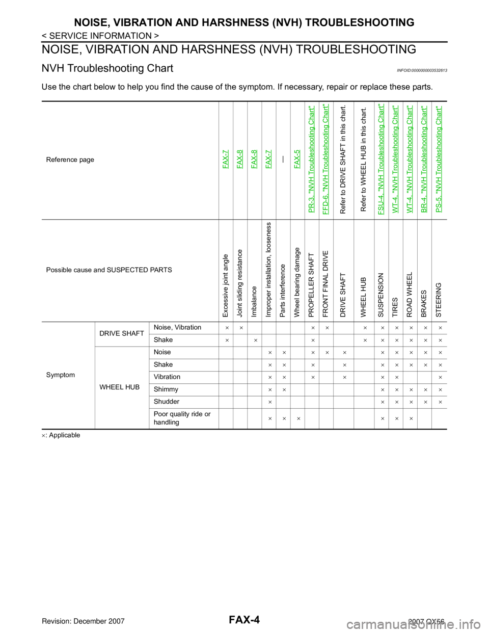
NVH Troubleshooting ChartINFOID:0000000003532613
Use the chart below to help you find the cause of the symptom. If necessary, repair or replace these parts.
×: ApplicableReference page
FAX-7FAX-8FAX-8FAX-7—
FAX-5
PR-3, "
NVH Troubleshooting Chart
"
FFD-6, "
NVH Troubleshooting Chart
"
Refer to DRIVE SHAFT in this chart.
Refer to WHEEL HUB in this chart.
FSU-4, "
NVH Troubleshooting Chart
"
WT-4, "
NVH Troubleshooting Chart
"
WT-4, "
NVH Troubleshooting Chart
"
BR-4, "
NVH Troubleshooting Chart
"
PS-5, "
NVH Troubleshooting Chart
"
Possible cause and SUSPECTED PARTS
Excessive joint angle
Joint sliding resistance
Imbalance
Improper installation, looseness
Parts interference
Wheel bearing damage
PROPELLER SHAFT
FRONT FINAL DRIVE
DRIVE SHAFT
WHEEL HUB
SUSPENSION
TIRES
ROAD WHEEL
BRAKES
STEERING
SymptomDRIVE SHAFTNoise, Vibration×× ×× × ×××× ×
Shake× × × × ×××× ×
WHEEL HUBNoise×× ×× × ×××× ×
Shake×× × × ×××× ×
Vibration×× × × ×× ×
Shimmy×× ×××× ×
Shudder× ×××× ×
Poor quality ride or
handling××× ×××
Page 1891 of 3061
WHEEL HUB
FAX-5
< SERVICE INFORMATION >
C
E
F
G
H
I
J
K
L
MA
B
FA X
N
O
P
WHEEL HUB
On-Vehicle Inspection and ServiceINFOID:0000000003532614
Make sure the mounting conditions (looseness, backlash) of each component and component status (wear,
damage) are normal.
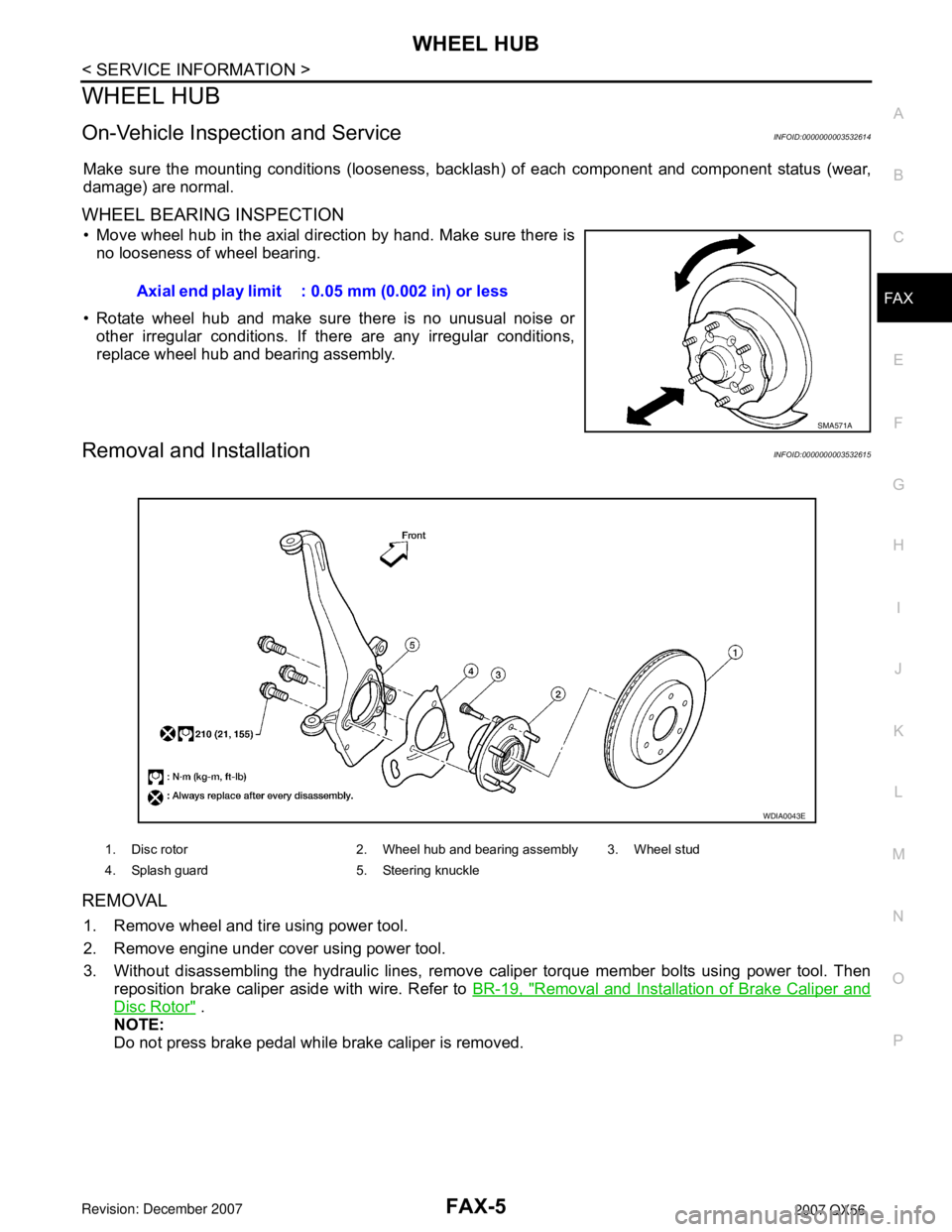
WHEEL BEARING INSPECTION
• Move wheel hub in the axial direction by hand. Make sure there is
no looseness of wheel bearing.
• Rotate wheel hub and make sure there is no unusual noise or
other irregular conditions. If there are any irregular conditions,
replace wheel hub and bearing assembly.
Removal and InstallationINFOID:0000000003532615
REMOVAL
1. Remove wheel and tire using power tool.
2. Remove engine under cover using power tool.
3. Without disassembling the hydraulic lines, remove caliper torque member bolts using power tool. Then
reposition brake caliper aside with wire. Refer to BR-19, "
Removal and Installation of Brake Caliper and
Disc Rotor" .
NOTE:
Do not press brake pedal while brake caliper is removed.Axial end play limit : 0.05 mm (0.002 in) or less
SMA571A
1. Disc rotor 2. Wheel hub and bearing assembly 3. Wheel stud
4. Splash guard 5. Steering knuckle
WDIA0043E
Page 1892 of 3061
FAX-6
< SERVICE INFORMATION >
WHEEL HUB
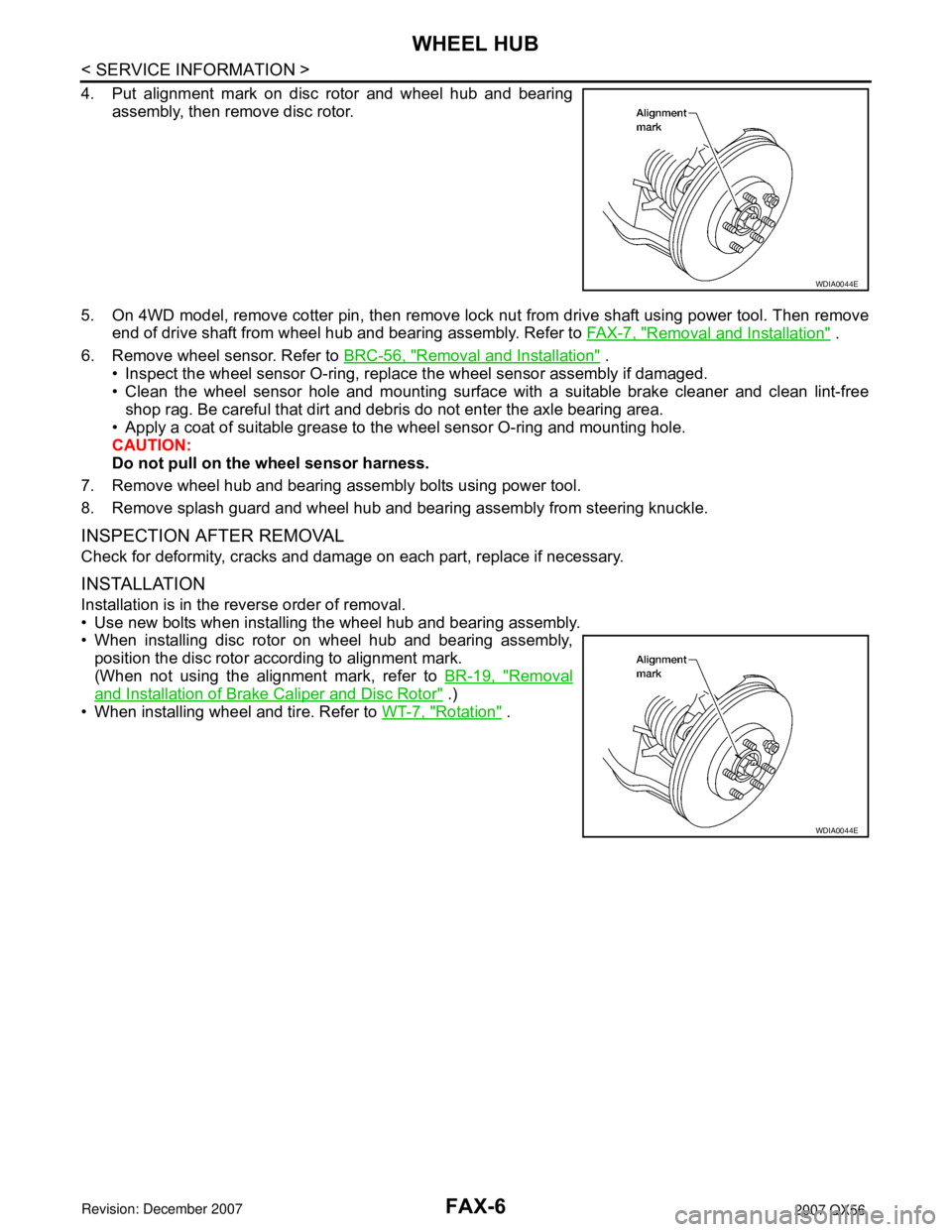
4. Put alignment mark on disc rotor and wheel hub and bearing
assembly, then remove disc rotor.
5. On 4WD model, remove cotter pin, then remove lock nut from drive shaft using power tool. Then remove
end of drive shaft from wheel hub and bearing assembly. Refer to FA X - 7 , "
Removal and Installation" .
6. Remove wheel sensor. Refer to BRC-56, "
Removal and Installation" .
• Inspect the wheel sensor O-ring, replace the wheel sensor assembly if damaged.
• Clean the wheel sensor hole and mounting surface with a suitable brake cleaner and clean lint-free
shop rag. Be careful that dirt and debris do not enter the axle bearing area.
• Apply a coat of suitable grease to the wheel sensor O-ring and mounting hole.
CAUTION:
Do not pull on the wheel sensor harness.
7. Remove wheel hub and bearing assembly bolts using power tool.
8. Remove splash guard and wheel hub and bearing assembly from steering knuckle.
INSPECTION AFTER REMOVAL
Check for deformity, cracks and damage on each part, replace if necessary.
INSTALLATION
Installation is in the reverse order of removal.
• Use new bolts when installing the wheel hub and bearing assembly.
• When installing disc rotor on wheel hub and bearing assembly,
position the disc rotor according to alignment mark.
(When not using the alignment mark, refer to BR-19, "
Removal
and Installation of Brake Caliper and Disc Rotor" .)
• When installing wheel and tire. Refer to WT-7, "
Rotation" .
WDIA0044E
WDIA0044E
Page 1893 of 3061
DRIVE SHAFT
FAX-7
< SERVICE INFORMATION >
C
E
F
G
H
I
J
K
L
MA
B
FA X
N
O
P
DRIVE SHAFT
Removal and InstallationINFOID:0000000003532616
REMOVAL
1. Remove wheel and tire using power tool.
2. Remove engine under cover using power tool.
3. Remove wheel sensor harness from mount on knuckle.
CAUTION:
Do not pull on wheel sensor harness.
4. Without disassembling the hydraulic lines, remove brake caliper using power tool. Reposition it aside with
wire. Refer to BR-19, "
Removal and Installation of Brake Caliper and Disc Rotor" .
NOTE:
Avoid depressing brake pedal while brake caliper is removed.
5. Remove coil spring and shock absorber assembly using power tool. Refer to FSU-10, "
Removal and
Installation" .
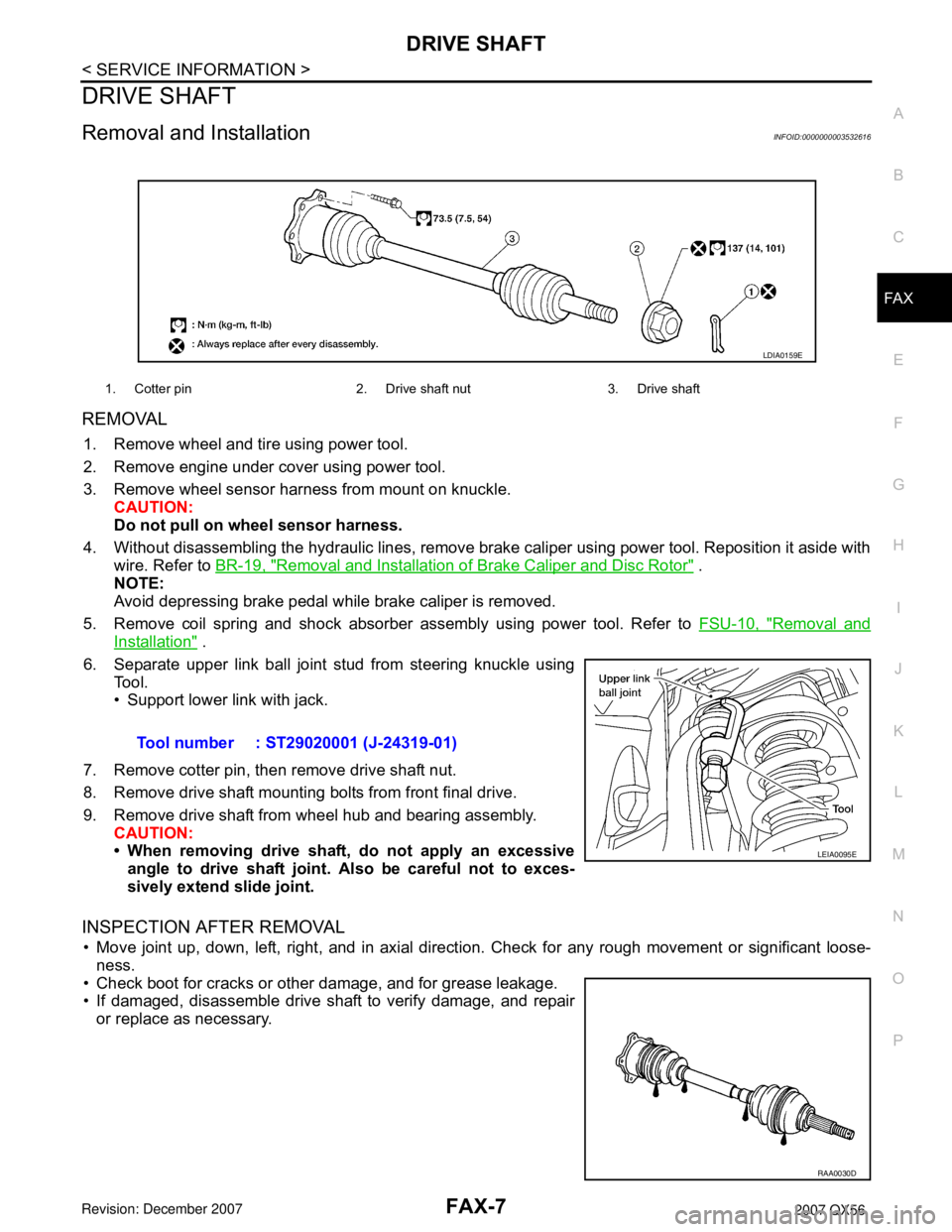
6. Separate upper link ball joint stud from steering knuckle using
Tool.
• Support lower link with jack.
7. Remove cotter pin, then remove drive shaft nut.
8. Remove drive shaft mounting bolts from front final drive.
9. Remove drive shaft from wheel hub and bearing assembly.
CAUTION:
• When removing drive shaft, do not apply an excessive
angle to drive shaft joint. Also be careful not to exces-
sively extend slide joint.
INSPECTION AFTER REMOVAL
• Move joint up, down, left, right, and in axial direction. Check for any rough movement or significant loose-
ness.
• Check boot for cracks or other damage, and for grease leakage.
• If damaged, disassemble drive shaft to verify damage, and repair
or replace as necessary.
1. Cotter pin 2. Drive shaft nut 3. Drive shaft
LDIA0159E
Tool number : ST29020001 (J-24319-01)
LEIA0095E
RAA0030D
Page 1905 of 3061

FFD-6
< SERVICE INFORMATION >
NOISE, VIBRATION AND HARSHNESS (NVH) TROUBLESHOOTING
NOISE, VIBRATION AND HARSHNESS (NVH) TROUBLESHOOTING
NVH Troubleshooting ChartINFOID:0000000003532587
Use the chart below to help you find the cause of the symptom. If necessary, repair or replace these parts.
×: ApplicableReference page
FFD-13FFD-13FFD-13FFD-13FFD-13FFD-7
PR-3, "
NVH Troubleshooting Chart
"
FAX-4, "
NVH Troubleshooting Chart
"
FSU-4, "
NVH Troubleshooting Chart
"
WT-4, "
NVH Troubleshooting Chart
"
WT-4, "
NVH Troubleshooting Chart
"
FAX-4, "
NVH Troubleshooting Chart
"
BR-4, "
NVH Troubleshooting Chart
"
PS-5, "
NVH Troubleshooting Chart
"
Possible cause and SUSPECTED PARTS
Gear tooth rough
Gear contact improper
Tooth surfaces worn
Incorrect backlash
Companion flange excessive runout
Gear oil improper
PROPELLER SHAFT
FRONT AXLE
FRONT SUSPENSION
TIRES
ROAD WHEEL
DRIVE SHAFT
BRAKES
STEERING
Symptom Noise××××××××××××××
Page 1950 of 3061

FSU-4
< SERVICE INFORMATION >
NOISE, VIBRATION AND HARSHNESS (NVH) TROUBLESHOOTING
NOISE, VIBRATION AND HARSHNESS (NVH) TROUBLESHOOTING
NVH Troubleshooting ChartINFOID:0000000003532634
Use the chart below to help you find the cause of the symptom. Repair or replace parts as necessary.
x: ApplicableReference page
FSU-5FSU-10FSU-5FSU-5FSU-20FSU-6FSU-6FSU-6
PR-3, "
NVH Troubleshooting Chart
"
FFD-6, "
NVH Troubleshooting Chart
"
FAX-4, "
NVH Troubleshooting Chart
"
FAX-4, "
NVH Troubleshooting Chart
"
WT-4, "
NVH Troubleshooting Chart
"
WT-4, "
NVH Troubleshooting Chart
"
BR-4, "
NVH Troubleshooting Chart
"
PS-5, "
NVH Troubleshooting Chart
"
Possible Cause and
SUSPECTED PARTS
Improper installation, looseness
Shock absorber deformation,
damage or deflection
Bushing or mounting deterioration
Parts interference
Spring fatigue
Suspension looseness
Incorrect wheel alignment
Stabilizer bar fatigue
PROPELLER SHAFT
FRONT FINAL DRIVE
DRIVE SHAFT
WHEEL HUB
TIRES
ROAD WHEEL
BRAKES
STEERING
SymptomNoise× × ×××× × × ×× × × ××
Shake× × ×× × × ×× × × ××
Vibration× × ××× × ×× × ×
Shimmy× × ×× × × × × ××
Shudder××× ×××××
Poor quality ride or handling××××× ×× ×××
Page 1969 of 3061
PRECAUTIONS
GI-3
< SERVICE INFORMATION >
C
D
E
F
G
H
I
J
K
L
MB
GI
N
O
P
General PrecautionINFOID:0000000003531471
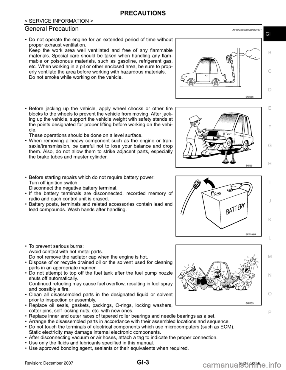
• Do not operate the engine for an extended period of time without
proper exhaust ventilation.
Keep the work area well ventilated and free of any flammable
materials. Special care should be taken when handling any flam-
mable or poisonous materials, such as gasoline, refrigerant gas,
etc. When working in a pit or other enclosed area, be sure to prop-
erly ventilate the area before working with hazardous materials.
Do not smoke while working on the vehicle.
• Before jacking up the vehicle, apply wheel chocks or other tire
blocks to the wheels to prevent the vehicle from moving. After jack-
ing up the vehicle, support the vehicle weight with safety stands at
the points designated for proper lifting before working on the vehi-
cle.
These operations should be done on a level surface.
• When removing a heavy component such as the engine or tran-
saxle/transmission, be careful not to lose your balance and drop
them. Also, do not allow them to strike adjacent parts, especially
the brake tubes and master cylinder.
• Before starting repairs which do not require battery power:
Turn off ignition switch.
Disconnect the negative battery terminal.
• If the battery terminals are disconnected, recorded memory of
radio and each control unit is erased.
• Battery posts, terminals and related accessories contain lead and
lead compounds. Wash hands after handling.
• To prevent serious burns:
Avoid contact with hot metal parts.
Do not remove the radiator cap when the engine is hot.
• Dispose of or recycle drained oil or the solvent used for cleaning
parts in an appropriate manner.
• Do not attempt to top off the fuel tank after the fuel pump nozzle
shuts off automatically.
Continued refueling may cause fuel overflow, resulting in fuel spray
and possibly a fire.
• Clean all disassembled parts in the designated liquid or solvent
prior to inspection or assembly.
• Replace oil seals, gaskets, packings, O-rings, locking washers,
cotter pins, self-locking nuts, etc. with new ones.
• Replace inner and outer races of tapered roller bearings and needle bearings as a set.
• Arrange the disassembled parts in accordance with their assembled locations and sequence.
• Do not touch the terminals of electrical components which use microcomputers (such as ECM).
Static electricity may damage internal electronic components.
• After disconnecting vacuum or air hoses, attach a tag to indicate the proper connection.
• Use only the fluids and lubricants specified in this manual.
• Use approved bonding agent, sealants or their equivalents when required.
SGI285
SGI231
SEF289H
SGI233
Page 1974 of 3061
GI-8
< SERVICE INFORMATION >
HOW TO USE THIS MANUAL
Contents
INFOID:0000000003531482
•ALPHABETICAL INDEX is provided at the end of this manual so that you can rapidly find the item and page
you are searching for.
•A QUICK REFERENCE INDEX, a black tab (e.g. ) is provided on the first page. You can quickly find the
first page of each section by matching it to the section's black tab.
•THE CONTENTS are listed on the first page of each section.
•THE TITLE is indicated on the upper portion of each page and shows the part or system.
•THE PAGE NUMBER of each section consists of two or three letters which designate the particular section
and a number (e.g. “BR-5”).
•THE SMALL ILLUSTRATIONS show the important steps such as inspection, use of special tools, knacks of
work and hidden or tricky steps which are not shown in the previous large illustrations.
Assembly, inspection and adjustment procedures for the complicated units such as the automatic transaxle
or transmission, etc. are presented in a step-by-step format where necessary.
ComponentINFOID:0000000003531483
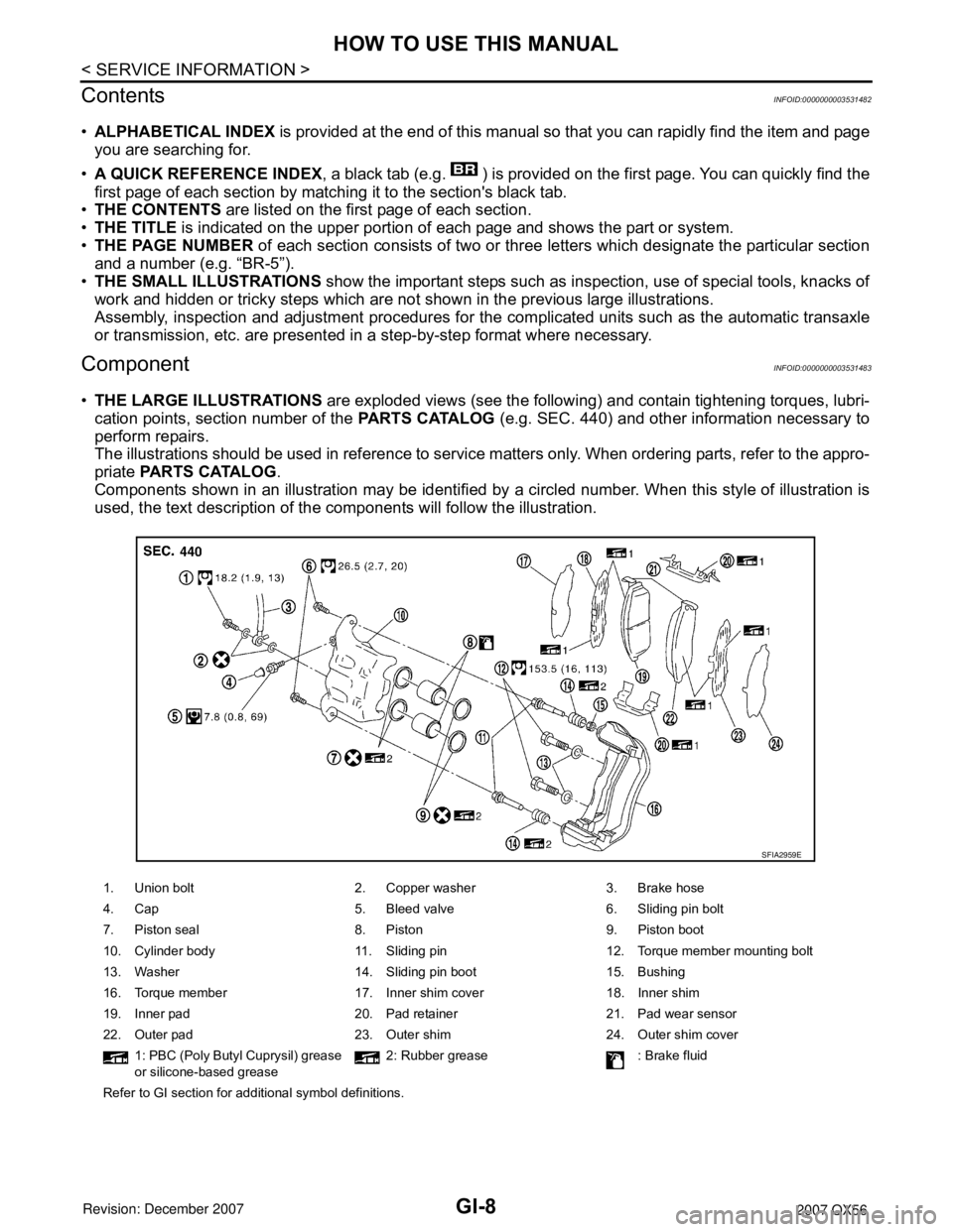
•THE LARGE ILLUSTRATIONS are exploded views (see the following) and contain tightening torques, lubri-
cation points, section number of the PARTS CATALOG (e.g. SEC. 440) and other information necessary to
perform repairs.
The illustrations should be used in reference to service matters only. When ordering parts, refer to the appro-
priate PARTS CATALOG.
Components shown in an illustration may be identified by a circled number. When this style of illustration is
used, the text description of the components will follow the illustration.
1. Union bolt 2. Copper washer 3. Brake hose
4. Cap 5. Bleed valve 6. Sliding pin bolt
7. Piston seal 8. Piston 9. Piston boot
10. Cylinder body 11. Sliding pin 12. Torque member mounting bolt
13. Washer 14. Sliding pin boot 15. Bushing
16. Torque member 17. Inner shim cover 18. Inner shim
19. Inner pad 20. Pad retainer 21. Pad wear sensor
22. Outer pad 23. Outer shim 24. Outer shim cover
1: PBC (Poly Butyl Cuprysil) grease
or silicone-based grease2: Rubber grease : Brake fluid
Refer to GI section for additional symbol definitions.
SFIA2959E
Page 1984 of 3061
GI-18
< SERVICE INFORMATION >
HOW TO USE THIS MANUAL
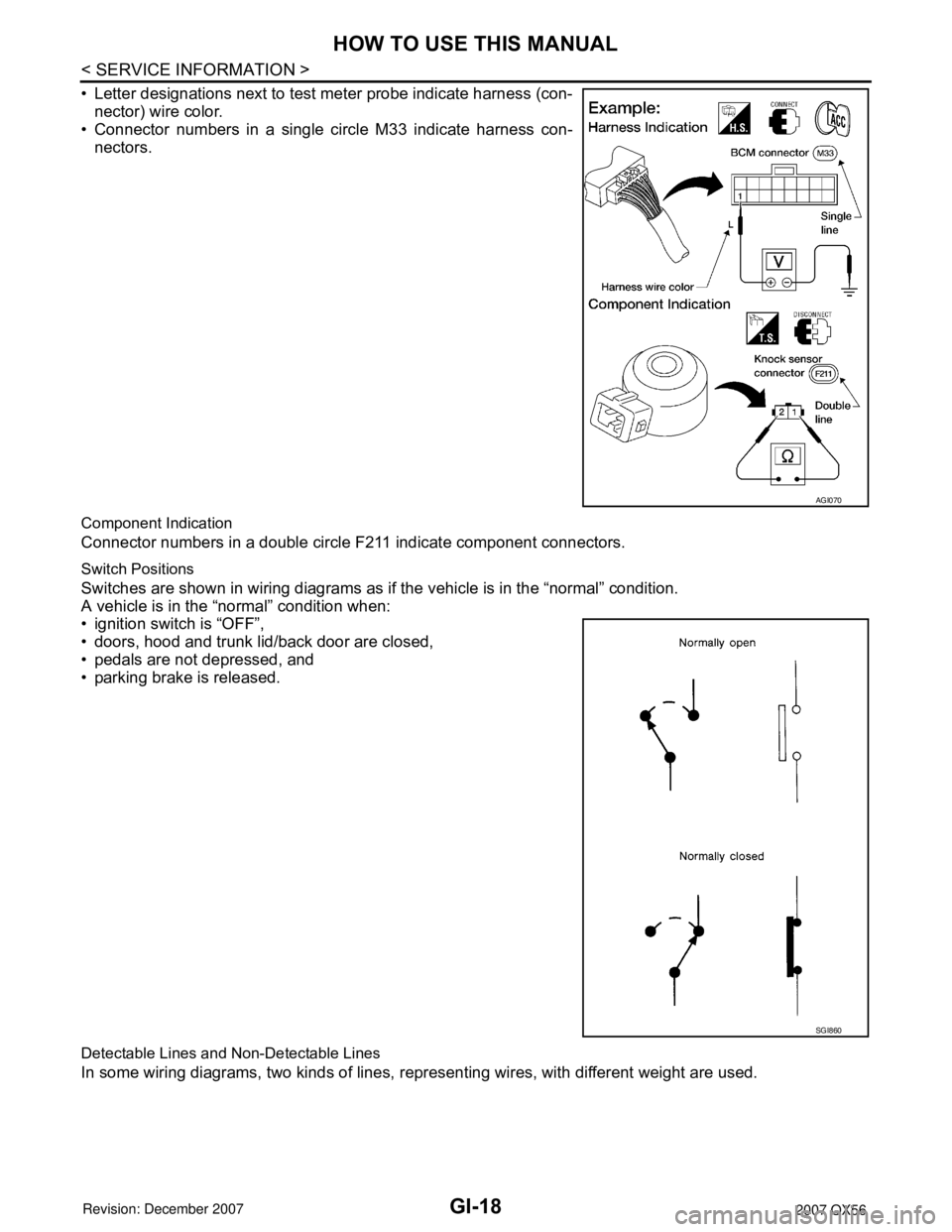
• Letter designations next to test meter probe indicate harness (con-
nector) wire color.
• Connector numbers in a single circle M33 indicate harness con-
nectors.
Component Indication
Connector numbers in a double circle F211 indicate component connectors.
Switch Positions
Switches are shown in wiring diagrams as if the vehicle is in the “normal” condition.
A vehicle is in the “normal” condition when:
• ignition switch is “OFF”,
• doors, hood and trunk lid/back door are closed,
• pedals are not depressed, and
• parking brake is released.
Detectable Lines and Non-Detectable Lines
In some wiring diagrams, two kinds of lines, representing wires, with different weight are used.
AGI070
SGI860
Page 2007 of 3061

LIFTING POINT
GI-41
< SERVICE INFORMATION >
C
D
E
F
G
H
I
J
K
L
MB
GI
N
O
P
• When setting the lift arm, do not allow the arm to contact the brake tubes, brake cable, or fuel lines.
WAIA0029E