warning INFINITI QX56 2007 Factory Service Manual
[x] Cancel search | Manufacturer: INFINITI, Model Year: 2007, Model line: QX56, Model: INFINITI QX56 2007Pages: 3061, PDF Size: 64.56 MB
Page 3011 of 3061

WT-22
< SERVICE INFORMATION >
TROUBLE DIAGNOSIS FOR SELF-DIAGNOSTIC ITEMS
Ignition Signal
INFOID:0000000003585170
MALFUNCTION CODE NO. 54 (DTC C1735)
1.CAN IGNITION SIGNAL
Check BCM IGN RLY signal with CONSULT-II.
Are the inspection results normal with the ignition switch ON?
YES >> GO TO 2.
NO >> Check CAN system.
2.BCM POWER SUPPLY
Check BCM power supply (ignition ON). Refer to BCS-15, "
BCM Power Supply and Ground Circuit Inspec-
tion".
Is the power supply with the ignition switch ON normal?
YES >> GO TO 3.
NO >> Repair power supply as necessary.
3.DRIVE VEHICLE
Clear DTC and then test drive the vehicle and check the low tire pressure warning lamp.
Does the vehicle operate without any low tire pressure warning lamp?
YES >> Inspection End.
NO >> Replace BCM. Refer to BCS-24, "
BCM".
Page 3012 of 3061

TROUBLE DIAGNOSIS FOR SYMPTOMS
WT-23
< SERVICE INFORMATION >
C
D
F
G
H
I
J
K
L
MA
B
WT
N
O
P
TROUBLE DIAGNOSIS FOR SYMPTOMS
Low Tire Pressure Warning Lamp Does Not Come On When Ignition Switch Is Turned
On
INFOID:0000000003532708
DIAGNOSTIC PROCEDURE
1.SELF-DIAGNOSTIC RESULT CHECK
Using CONSULT-II, check display contents in self-diagnostic results.
Is "CAN COMM CIRCUIT" displayed in the self-diagnosis display items?
YES >> Malfunction in CAN communication system. GO TO LAN-40.
NO >> GO TO 2.
2.CHECK COMBINATION METER
Check combination meter operation. Refer to DI-12, "
Self-Diagnosis Mode of Combination Meter".
Inspection results OK?
OK >> GO TO 3.
NG >> Replace combination meter. Refer to IP-10, "
Removal and Installation".
3.CHECK LOW TIRE PRESSURE WARNING LAMP
Disconnect BCM harness connector.
Does the low tire pressure warning lamp activate?
YES >> Replace BCM. Refer to BCS-24, "BCM".
NO >> Check combination meter operation. Refer to DI-12, "
Self-Diagnosis Mode of Combination
Meter".
Low Tire Pressure Warning Lamp Stays On When Ignition Switch Is Turned On
INFOID:0000000003532709
DIAGNOSTIC PROCEDURE
1.CHECK BCM CONNECTORS
1. Turn ignition switch OFF.
2. Disconnect BCM harness connectors M18 and M20.
3. Check terminals for damage or loose connections.
Inspection results OK?
OK >> GO TO 2.
NG >> Repair or replace damaged parts.
2.CHECK BCM POWER SUPPLY CIRCUIT (BAT)
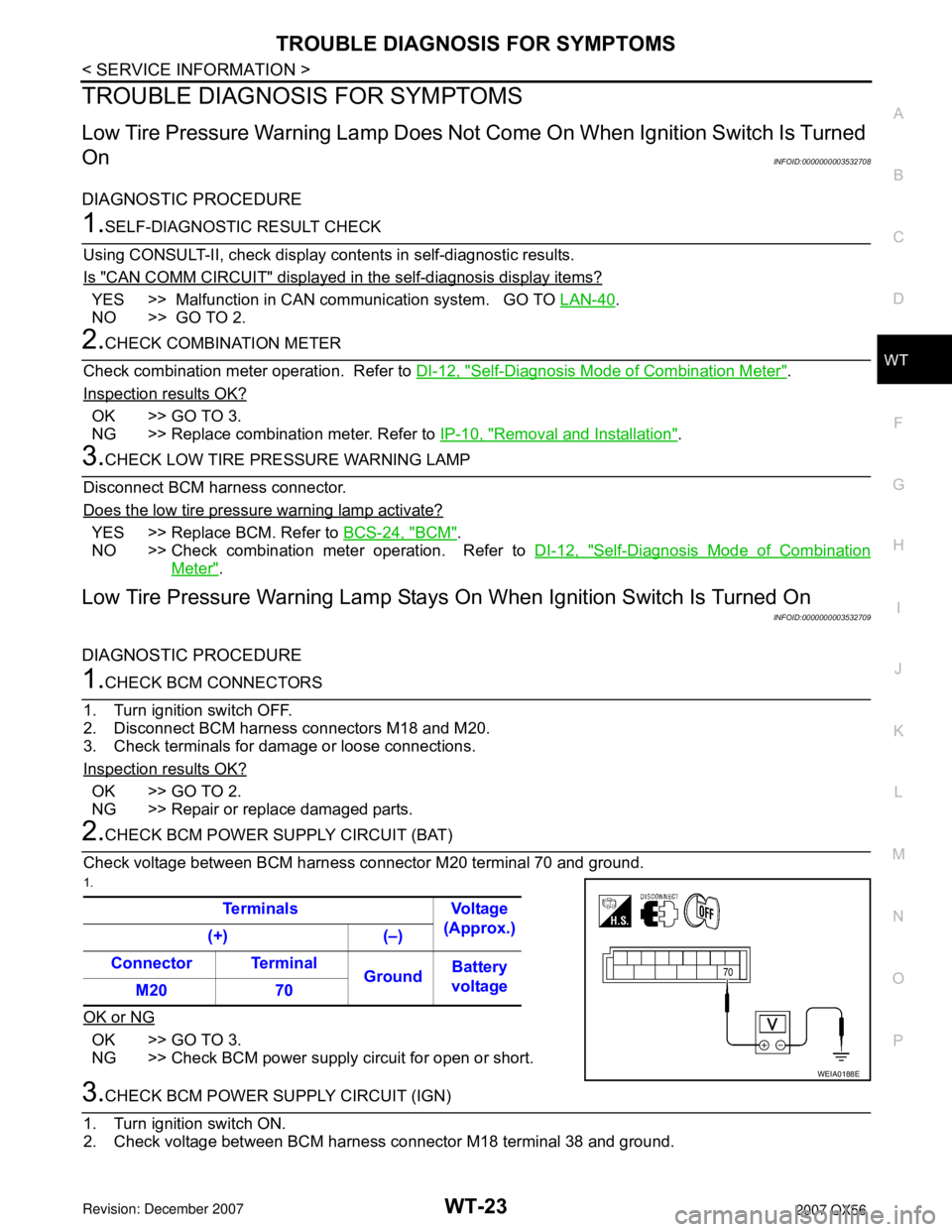
Check voltage between BCM harness connector M20 terminal 70 and ground.
1.
OK or NG
OK >> GO TO 3.
NG >> Check BCM power supply circuit for open or short.
3.CHECK BCM POWER SUPPLY CIRCUIT (IGN)
1. Turn ignition switch ON.
2. Check voltage between BCM harness connector M18 terminal 38 and ground.Terminals Voltage
(Approx.)
(+) (–)
Connector Terminal
GroundBattery
voltage
M20 70
WEIA0188E
Page 3013 of 3061

WT-24
< SERVICE INFORMATION >
TROUBLE DIAGNOSIS FOR SYMPTOMS
OK or NG
OK >> GO TO 4.
NG >> Check BCM power supply circuit for open or short.
4.CHECK BCM GROUND CIRCUIT
1. Turn ignition switch OFF.
2. Check continuity between BCM harness connector M20 terminal 67 and ground.
OK or NG
OK >> Replace BCM. Refer to BCS-24, "BCM".
NG >> Repair BCM ground circuit.
Low Tire Pressure Warning Lamp Flashes When Ignition Switch Is Turned On
INFOID:0000000003532710
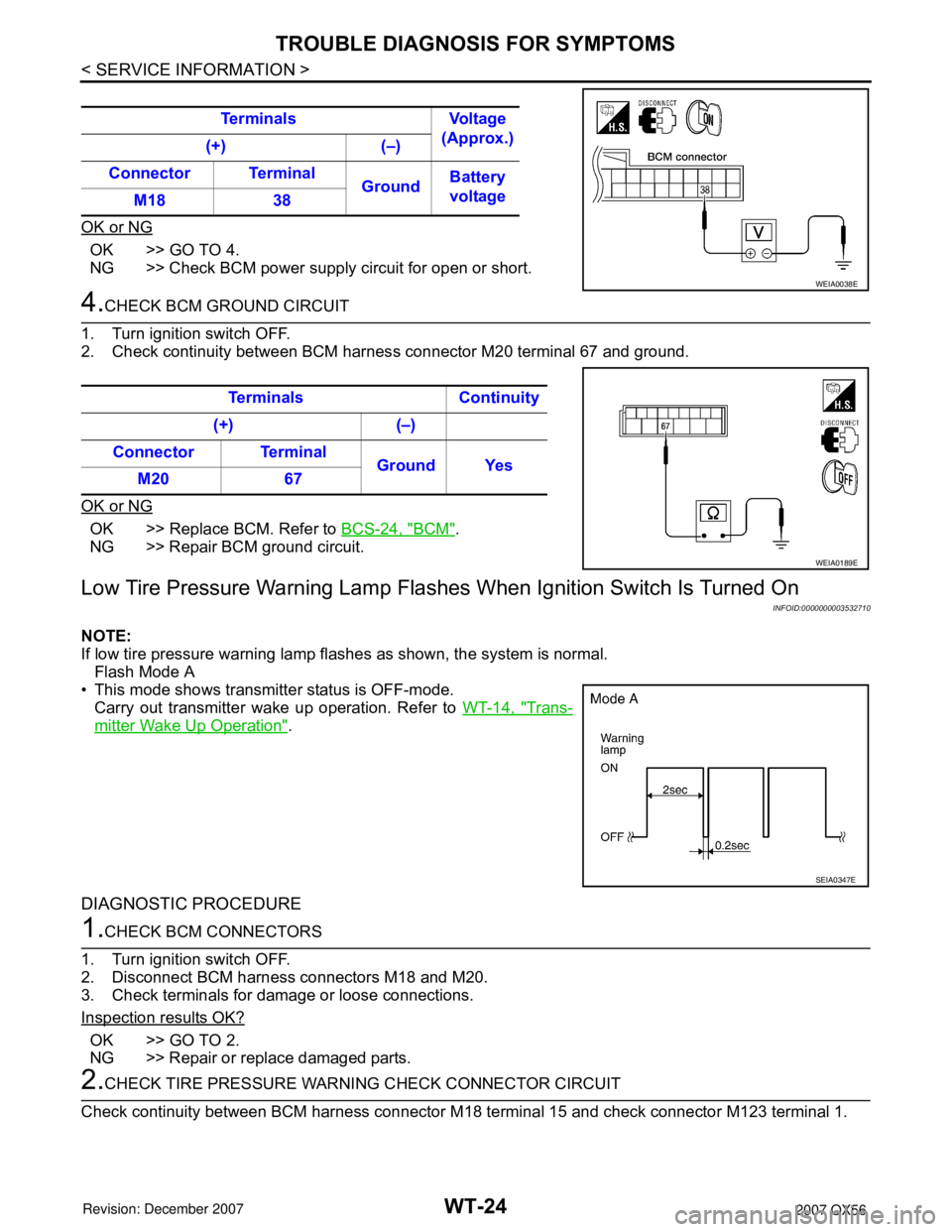
NOTE:
If low tire pressure warning lamp flashes as shown, the system is normal.
Flash Mode A
• This mode shows transmitter status is OFF-mode.
Carry out transmitter wake up operation. Refer to WT-14, "
Trans-
mitter Wake Up Operation".
DIAGNOSTIC PROCEDURE
1.CHECK BCM CONNECTORS
1. Turn ignition switch OFF.
2. Disconnect BCM harness connectors M18 and M20.
3. Check terminals for damage or loose connections.
Inspection results OK?
OK >> GO TO 2.
NG >> Repair or replace damaged parts.
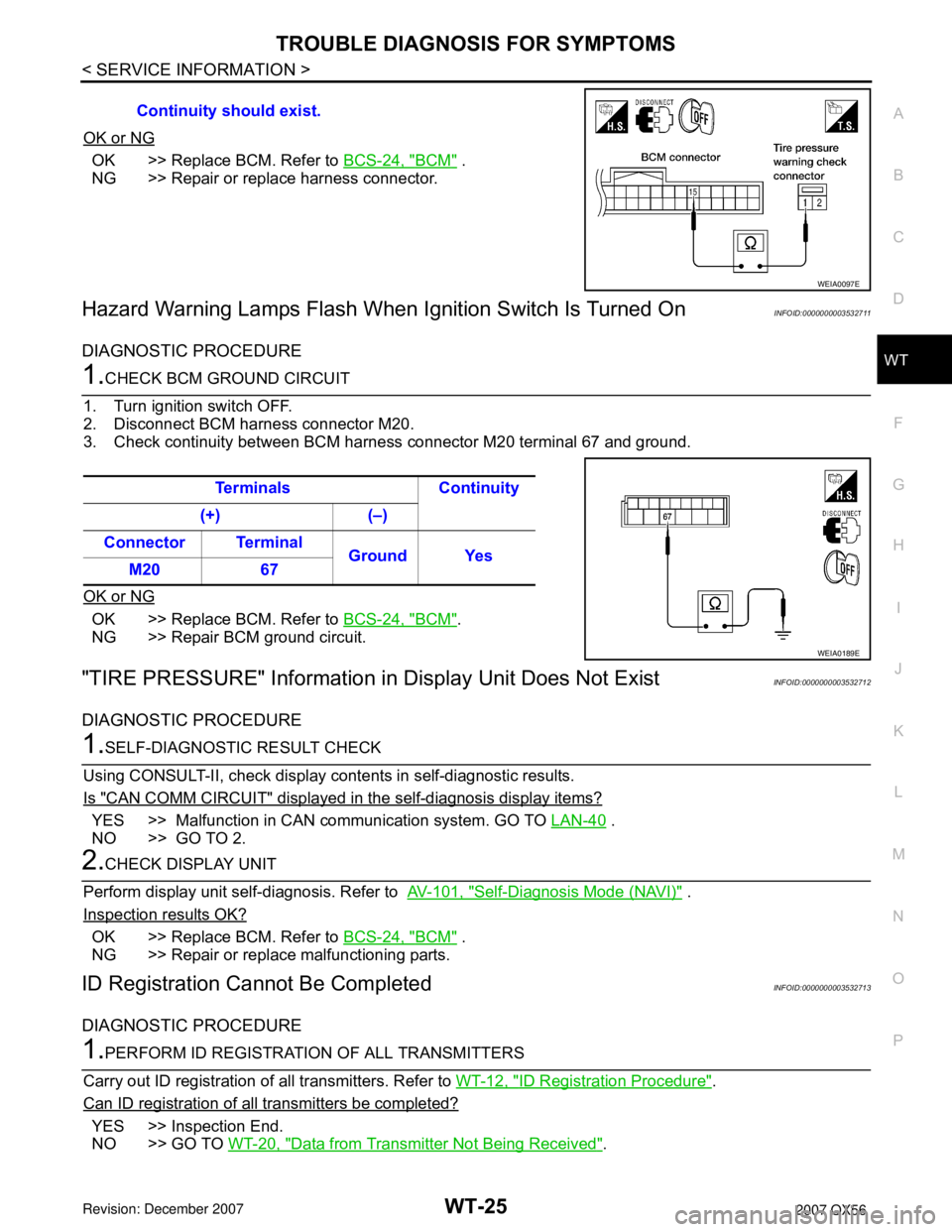
2.CHECK TIRE PRESSURE WARNING CHECK CONNECTOR CIRCUIT
Check continuity between BCM harness connector M18 terminal 15 and check connector M123 terminal 1. Terminals Voltage
(Approx.)
(+) (–)
Connector Terminal
GroundBattery
voltage
M18 38
WEIA0038E
Terminals Continuity
(+) (–)
Connector Terminal
Ground Yes
M20 67
WEIA0189E
SEIA0347E
Page 3014 of 3061

TROUBLE DIAGNOSIS FOR SYMPTOMS
WT-25
< SERVICE INFORMATION >
C
D
F
G
H
I
J
K
L
MA
B
WT
N
O
P
OK or NG
OK >> Replace BCM. Refer to BCS-24, "BCM" .
NG >> Repair or replace harness connector.
Hazard Warning Lamps Flash When Ignition Switch Is Turned OnINFOID:0000000003532711
DIAGNOSTIC PROCEDURE
1.CHECK BCM GROUND CIRCUIT
1. Turn ignition switch OFF.
2. Disconnect BCM harness connector M20.
3. Check continuity between BCM harness connector M20 terminal 67 and ground.
OK or NG
OK >> Replace BCM. Refer to BCS-24, "BCM".
NG >> Repair BCM ground circuit.
"TIRE PRESSURE" Information in Display Unit Does Not ExistINFOID:0000000003532712
DIAGNOSTIC PROCEDURE
1.SELF-DIAGNOSTIC RESULT CHECK
Using CONSULT-II, check display contents in self-diagnostic results.
Is "CAN COMM CIRCUIT" displayed in the self-diagnosis display items?
YES >> Malfunction in CAN communication system. GO TO LAN-40 .
NO >> GO TO 2.
2.CHECK DISPLAY UNIT
Perform display unit self-diagnosis. Refer to AV-101, "
Self-Diagnosis Mode (NAVI)" .
Inspection results OK?
OK >> Replace BCM. Refer to BCS-24, "BCM" .
NG >> Repair or replace malfunctioning parts.
ID Registration Cannot Be CompletedINFOID:0000000003532713
DIAGNOSTIC PROCEDURE
1.PERFORM ID REGISTRATION OF ALL TRANSMITTERS
Carry out ID registration of all transmitters. Refer to WT-12, "
ID Registration Procedure".
Can ID registration of all transmitters be completed?
YES >> Inspection End.
NO >> GO TO WT-20, "
Data from Transmitter Not Being Received". Continuity should exist.
WEIA0097E
Terminals Continuity
(+) (–)
Connector Terminal
Ground Yes
M20 67
WEIA0189E
Page 3019 of 3061

WW-2
< SERVICE INFORMATION >
PRECAUTION
SERVICE INFORMATION
PRECAUTION
Precaution for Supplemental Restraint System (SRS) "AIR BAG" and "SEAT BELT
PRE-TENSIONER"
INFOID:0000000003533550
The Supplemental Restraint System such as “AIR BAG” and “SEAT BELT PRE-TENSIONER”, used along
with a front seat belt, helps to reduce the risk or severity of injury to the driver and front passenger for certain
types of collision. This system includes seat belt switch inputs and dual stage front air bag modules. The SRS
system uses the seat belt switches to determine the front air bag deployment, and may only deploy one front
air bag, depending on the severity of a collision and whether the front occupants are belted or unbelted.
Information necessary to service the system safely is included in the SRS and SB section of this Service Man-
ual.
WARNING:
• To avoid rendering the SRS inoperative, which could increase the risk of personal injury or death in
the event of a collision which would result in air bag inflation, all maintenance must be performed by
an authorized NISSAN/INFINITI dealer.
• Improper maintenance, including incorrect removal and installation of the SRS, can lead to personal
injury caused by unintentional activation of the system. For removal of Spiral Cable and Air Bag
Module, see the SRS section.
• Do not use electrical test equipment on any circuit related to the SRS unless instructed to in this
Service Manual. SRS wiring harnesses can be identified by yellow and/or orange harnesses or har-
ness connectors.